


Services on Demand
Journal

Article
 English (pdf)
 Article in xml format
 Article references
 Send this article by e-mail
Indicators
Related links
-
 Cited by Google
 -
 Similars in Google
Share

 Permalink
R&D Journal
On-line version ISSN 2309-8988Print version ISSN 0257-9669
R&D j. (Matieland, Online) vol.16 Stellenbosch, Cape Town 2000
The solar chimney air standard thermodynamic cycle
T.W. von BackströmI; A.J. GannonII
IDepartment of Mechanical Engineering, University of Stellenbosch, Private Bag XI, Matieland, 7602 South Africa
IIDepartment of Mechanical Engineering, University of Stellenbosch
ABSTRACT
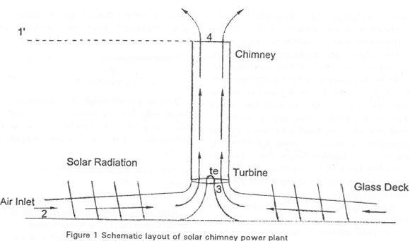
The paper presents an air standard thermodynamic analysis for the solar chimney cycle. A solar chimney is a power plant in which air, heated under a glass-decked solar collector, escapes through a power generating turbine at the base of a chimney. Simple equations were derived for the cycle efficiency, power per unit mass flow and available turbine pressure drop, assuming ideal air as process gas and ideal reversible processes. The main conclusions were the following: the cycle efficiency is directly proportional to the chimney height; unlike the gas turbine cycle, there is no optimal pressure ratio (chimney height) for maximum specific power; the power per unit mass flow developed by the plant is directly proportional to the cycle efficiency and the temperature rise in the solar collector; the pressure drop across the turbine is proportional to the chimney height and the collector temperature rise. A design condition where the chimney exit temperature equals the collector inlet temperature was also proposed for initial calculations. The specific power of the plant is then approximately proportional to the square of the cycle efficiency. The analysis enables one to do initial sizing of a plant for a given required power.
Introduction
A solar chimney power plant consists of a large area covered by glass or translucent plastic sheets to collect solar energy. A central, high chimney, containing a power generating turbine at its base, allows the hot air to escape. Haaf et al.1 and Haaf2 discussed the operation of a prototype solar chimney plant.
The thermodynamic processes occurring in a solar chimney could be presented as a thermodynamic cycle. Air standard cycles are simplified thermodynamic cycles that are useful in the understanding of the real cycles that they simulate. They are so named because their working fluid is assumed to be air behaving as perfect gas. Their analytical nature serves to point out the main relationships between variables, and the most important trends in the way they affect each other. The results obtained from air standard analyses are intended to render limiting (not realistic) values of variables such as efficiency and specific power. Extended analyses including pressure losses, component efficiencies, such as the solar collector efficiency, and variable air properties, are beyond the scope of an air standard analysis and will be published elsewhere.
Many investigators, for example Wilson,3 Cohen et al.,4 Oates5 and Archer & Saarlas,6 have found it instructive to develop air standard cycles for gas turbine and other thermodynamic cycles. Some aspects of the thermodynamics of the solar chimney cycle have been investigated, for example, by Schlaich7 and Stephan et al.8 but a complete air standard cycle analysis for the solar chimney could not be found.
Objectives of the study
The objectives of this report are as follows:
• To develop a solar chimney air standard cycle
• To use the models to determine the existence of optima if any
• To determine the efficiency potential of the cycle
• To determine the power generating potential of the cycle
• To determine the available turbine pressure drop of the cycle
• To investigate in principle what cycle modifications are necessary and feasible
Assumptions for air standard analyses
The usual assumptions for air standard cycles are as follows:
• The working fluid is dry air, considered as a constant composition perfect gas throughout, with constant specific heat
• The mass flow through the system is constant
• Compression and expansion processes are adiabatic and reversible (isentropic)
• The change in kinetic energy of the air between inlet and exit of each component is negligible
• There are no stagnation pressure drops in the combustor or connecting ducts and passages
• Inlet and exit atmospheric conditions are identical
• The only heat flow is the net heat flow into the air in the system
The solar chimney as a gas turbine
The first observation is that the solar chimney cycle is fundamentally a gas turbine (Joule or Bray ton) cycle. Let us consider the gas turbine air standard cycle. The four processes are isentropic compression, constant pressure heat addition, isentropic expansion and constant pressure heat removal.
In a standard gas turbine cycle the inlet and exhaust environmental conditions are assumed to be identical, and the only thermodynamic function of the surrounding air is to complete the cycle by cooling the exhaust air back to the inlet air temperature. In a solar chimney, however, the exhaust is at the altitude of the chimney top, and the atmosphere has the additional function of recompressing the exhaust air to the ground inlet conditions. This compression is not necessarily isentropic, but can generally be approximated by a polytropic process of the form p/pn = constant, with p and p equal to pressure and density, and n some exponent that is not necessarily equal to the specific heat ratio 7. However, Lenschow9 states that when the earth's surface is warmer than the overlying air or when the wind is moderately strong, efficient vertical mixing occurs in the convective atmospheric boundary layer. If no clouds are present this mixing results in a nearly adiabatic lapse rate through most of this turbulent layer. These may indeed be the prevalent atmospheric conditions in desert areas where the solar chimney plant are likely to be built. For the present analysis we shall assume an adiabatic lapse rate.
We shall first look at the simulation of the solar chimney cycle by a standard gas turbine air cycle where the chimney is eliminated and an isentropic compressor driven by the turbine is added. To better simulate the environmental conditions of the solar chimney plant we assume that the gas turbine plant is situated at the physically impractical altitude of the chimney top. The pressure ratio is chosen to be equal to the ratio of ground level atmospheric pressure to atmospheric pressure at the solar chimney top. The gas turbine then has the same cycle pressure ratio as the solar chimney plant it simulates. Such a real gas turbine solar concept would have other major practical disadvantages, such as the collector pressure being higher than local atmospheric (at chimney top altitude), and the huge amount of power to be transmitted between turbine and compressor. The low temperature solar gas turbine cycle will however serve as a useful benchmark for the solar chimney cycle.
Air standard analysis of solar powered gas turbine cycle
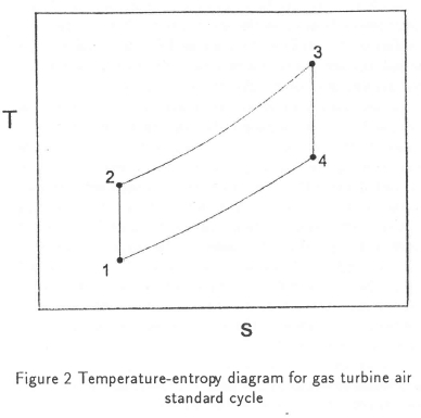
The T-s diagram in Figure 2 shows the cycle and the numbering used for the conditions between the processes in the cycle. The analysis below follows Cohen et al.4 and Archer & Saarlas.6 The definitions below are used to simplify the writing of the equations:
Cycle pressure ratio:
r = P2/P1 = P3/P4
Compression temperature ratio:
c = T2/Ti
= r (γ-l)/γ
The cycle efficiency is defined as the turbine output power divided by the thermal power transferred to the air in the solar collector. For the assumptions and conditions mentioned above it can be shown that the following holds for the efficiency:
Cycle efficiency:
N = 1-1/c
= 1 - l/r(γ-l)/γ
This is a very simple but important relationship, especially for low temperature ratio ideal cycles. It shows that the plant cycle efficiency is a function of pressure ratio only and not of cycle temperature ratio, t, defined below.
The cycle temperature ratio is:
t = T3/T1
= (T2 + ΔT23)/ T1
Here ΔT23 is the temperature rise in the collector, T2 is the compressor exit temperature.
As shown by Cohen et al.4 the specific power of an ideal gas turbine, as normalised with T\ in terms of t and c is:
P1* = Pshaft/ (mcpT)
= {(t/c)-l}(c-l)
The equation above implies that the specific power depends on pressure ratio as well as collector temperature rise (or power input per unit mass flow). It is clear that the specific power increases with plant temperature ratio (or collector temperature rise), but the effect of compression ratio cannot be seen just by inspection. The significance of the specific power is that the size and capital costs of a plant are determined largely by the mass flow through it. For any given value of t the relationship above can be differentiated with respect to c and equated to zero. The result is:
copt - y√t
The value of the optimum specific power is then:
As pointed out by Cohen et al.4 this optimum occurs when the turbine and compressor exit temperatures are equal, i.e. when T2 = T4. The optimum specific power can also be expressed in terms of the optimal cycle pressure ratio:
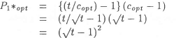
P1*opt - (Copt - 1)2
The general implication of the two equations for optimal power output is then that when an optimum combination of cycle temperature and pressure ratio is chosen, the specific power can be expressed as a function of one of them alone. Combinations off the optimal will progressively reduce the specific power output compared to the optimum as they deviate from it.
For a low temperature gas turbine air standard cycle simulating a solar chimney cycle the most important conclusions are:
• Cycle efficiency depends on cycle pressure ratio only
• For each cycle temperature ratio there is an optimal pressure ratio for maximum power per unit mass flow
Air standard analysis of solar chimney cycle
The analysis of the solar chimney cycle proceeds largely as for the gas turbine cycle except for the following:
• The compression process does not occur in the system, but in the environment, as the air descends. We have pointed out that isentropic compression may be a realistic process in desert conditions. However, we shall not enforce that condition strictly during the analysis.
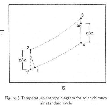
• Any reference in the analysis to the compression inlet temperature Tl will be avoided, because this is a variable temperature determined by the point where the constant pressure cooling line from point 4 intersects the polytropic (not isentropic) compression line to point 2. See Figure 3. Use will be made however of the point 1', the intersection between the constant pressure line through point 4 and the isentropic line through point 2.
A convenient reference temperature in the cycle is the collector inlet temperature, T2, since it is the ground level environmental temperature.
As before, the cycle efficiency is:
N = (Shaft power out) / (Solar power in)
The solar power input is:
P23 = mcp (T3-T2)
The shaft power out is:
Pshaft - m cp (T3 -T4) - m cp (T2 - Ti')
Why the second term, m cp (T2 - T1') must be subtracted for the solar chimney cycle is explained in the following paragraphs.
The power that could in principle be extracted from the flow by an ideal turbine as it expands from the collector exit pressure, p3 to the chimney exit pressure, p4, is m Cp (T3 - T4), but not all of it is available as shaft power.
Consider the section of the chimney between the turbine exit and the chimney exit. The power required to lift the air in the chimney is mgΔz. There is no heat transfer or shaft work in this section of the chimney. Energy conservation then determines the enthalpy change in the chimney to be Δh = cp(T4 - Tte) = -gΔz.
The energy exchange is isentropic, following from the assumption of zero friction and heat transfer. The magnitude of Ah may also be evaluated by considering the air as it descends again in the atmosphere after having been cooled to T1'. If heat transfer and frictional effects are small, the process is reversed and the enthalpy increases by the amount Δh = g Δz = cp(T2 - T1').
In the argument above we made some assumptions that will now be discussed. To construct the thermodynamic cycle one has to follow the flow from the chimney exit through the atmosphere where we assume that it is cooled down at constant pressure to the same entropy value as at the collector inlet. An isentropic compression between this point, at temperature T1 and the collector inlet at temperature T2 completes the cycle. If the process through which the air goes between the chimney exit and collector inlet follows some other path, determined by the atmospheric model, the idealized cycle may still be used for developing the analysis, as long as the imaginary temperature T1' is factored out during the analysis. This may be done because state point 1' describes a condition external to the solar chimney, and is merely a construct used to develop the air standard analysis.
Although the air standard gas turbine and solar chimney cycle T-s diagrams are similar, there are some differences. In the gas turbine cycle, energy is transferred from the turbine to the compressor as shaft work, that is, energy is extracted from the cycle by the turbine and reintroduced by the compressor. In the solar chimney cycle there is an internal exchange between enthalpy and geopotential energy in the chimney, and the process is reversed in the external environment. In spite of the differences the gas turbine air standard cycle analysis can be applied directly to the solar chimney cycle since similar enthalpy and entropy changes occur in the two air standard cycles.
In the solar chimney cycle the pressure ratio is defined in terms of the chimney exit and collector exit pressures:
r = P3/P4
and the compression temperature ratio is:
c = r(γ-l)/γ
As for the gas turbine cycle the cycle efficiency is then:
N = 1-1/c
= (T2-T1')/T2
Since:
Cp (T2-T1') = g Δz
N = gΔz/(cpT2)
The cycle efficiency of an ideal solar chimney plant is directly proportional to the chimney height, and inversely proportional to the collector inlet temperature. Schlaich7 uses the definition above for the efficiency of the chimney only, and defines a plant efficiency that includes the solar collector heat losses.
The cycle temperature ratio is defined as with T1', as discussed above:
t = T3/T1/
For the solar chimney cycle the specific power is normalized with respect to the collector inlet temperature, T2:
P2* = P/(mcpT2)
= mcp (T3-TA)-mcp (T2 - T1') / (m cp T2)
- (T3-T4)/T2-(T2-T1')/T2
= (t/c) (1-1/c) -(1-1/c)
, = (t/c-I) (1-1/c)
It is tempting to differentiate this equation with respect to c for fixed t as for the gas turbine cycle, but for the solar chimney t does not remain constant when c changes, because T\ decreases with altitude as chimney height (and c) increases. In other words t is a function of c:
t = T3/T1'
= (T2 + ΔT23) c/T2
= c(l + ΔT23/T2)
So:
P2* = (ΔT23/T2) (1-1/c)
If ΔT23 and T2 are fixed, P2* will be maximized by maximizing c (i.e. chimney height). There is then no optimum chimney height that maximizes specific power. Similarly, there is no optimum collector temperature rise that maximizes specific power for a fixed chimney height. Any increase in collector temperature rise will increase the specific power.
The specific power can be written in terms of 77 as follows:
P2* =(ΔT23/T2)N
The specific power can be written in terms of Az as follows:
P2* = (ΔT23/T2)(gΔz/cpT2)
The power output of an ideal solar chimney plant is then:
P = mcpT2P2*
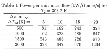
= mgΔz ΔT23/T2
The equation above shows that the specific power is proportional to the chimney height and the collector temperature rise, and inversely proportional to the collector inlet temperature. The required specific power can be obtained by any suitable combination of Az or ΔT23, or in other words by any suitable combination of chimney height and collector area. The choice will ultimately be determined by the relative costs of chimney and collector. Very high chimneys will be expensive, and may promote condensation in the chimney, and very large collectors will be expensive, and inefficient due to high radiation losses.
Table 1 gives the power per unit mass flow for various combinations of chimney height and collector temperature rise.
The available pressure drop across the turbine may now be calculated. We define the available temperature and pressure ratio across the turbine as follows, where subscript "te" denotes turbine exit:
tt = T3/Tte
and:
rt = p3/pte
The plant output power may be expressed as follows:
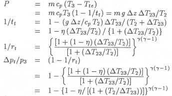
The equation above was used to draw up Table 2.
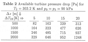
For incompressible flow we may assume that P = Q3Δpt where Q3 is the volume flow m/p3 at the turbine inlet. The available turbine pressure drop Δpt is then:
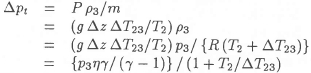
When the available turbine pressure drop is calculated with this equation for Δz = 2000 m and ΔT23 = 20 K, then Δpt - 1255 Pa, which corresponds to within 0.5 % with the value in the table above. The incompressible approximation, which can also be derived as the first term binomial expansion of the compressible equation, is accurate enough for the present simple analysis.
Bearing in mind that p2 - Pz the available turbine pressure drop may also simply be written in terms of atmospheric ground level density p2 as:
Δpt = p2 g Δz ΔT23/T3
Schlaich7 gives a similar equation. This is as far as we can go when the system is considered to have no pressure losses.
Practical application of air standard analysis
It is useful in the application of the theory to make a few simple additional assumptions. Schlaich7 points out that -the maximum power that can be generated occurs when two thirds of the drop in total pressure in the system is across the turbine. It can easily be shown that this applies to any system with a fixed available pressure difference and a loss proportional to flow squared. So only two-thirds of the pressure drop is available to drive the turbine, and the power extraction is reduced by the same factor. The fact that a third of the pressure losses are associated with system losses may be used to calculate the optimum chimney draught velocity. Since the velocity in the chimney increases as the density decreases due to expansion across the turbine and with altitude in the chimney, we have to choose a reference station. As reference position we choose the velocity at the chimney base, before the turbine. The chimney exit loss referred to this position will be larger than 1.0, because of the chimney exit velocity is larger than the chimney base velocity.
Kp3Vc2/2 = Δpt/3
KVS/2 = (Δpt/p3)/3 = (l/3) P/m
Ve = [2/(3K)]0.5(P/m)0.5
To allow for all the effects, we assume a constant system loss coefficient referred to the chimney base velocity of K = 2.0.
Table 3 shows that for the chosen conditions the chimney base velocity for maximum power can be given approximately by:
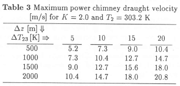
Vc = (ΔT23Δz/1000)0,5
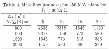
The mass flow required for a 250 MW plant is calculated as follows below. (In this analysis we assume
the turbine efficiency to be 100%, but with an 80% turbine efficiency the output would be 200 MW.) The construction of a large plant of 200 MW is currently being considered.
m250MW = 250 X 106/ {(2/3) P/m}
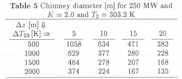
The appropriate chimney diameter is calculated as follows:
m = pAcVc
= [p2/{R(T2 + ΔT23)}](∏/4)D2V
D2 = 4mR(T2 + ΔT23)/(∏p2V)
Tables 4 and 5 show that a 250 MW plant (with a 100% efficient turbine) designed for a temperature rise of 20 K and a chimney height, requires a chimney diameter of about 170 m.
A possible design condition
One of the disadvantages of the analysis so far is that it does not lead to any preferential solar collector temperature rise for a given chimney height or vice versa. A possible preferential combination of parameters is the one implied by c = √t. In the case of the solar chimney it is not an optimal combination in the sense that it maximizes the specific power. We propose to choose this combination as a basis for initial design. In recognition of this fact, the subscript "d" (for design) will be used instead of "opt".
The choice of a design condition with cd = y√t implies the following:
• Neither the collector size nor the chimney height will be extreme
• The chimney exit temperature, T4, is equal to the solar collector inlet temperature, T2
• The condition above means that such a cycle will not benefit from the introduction of a heat exchanger, using exit air to heat entry air
• Condensation in the chimney will be unlikely even if the air is saturated at the collector inlet, as the chimney exit condensation temperature will be only a few degrees below the collector inlet temperature due to the decrease in pressure in the chimney
We shall now derive the dependence of collector tem-perature.rise on chimney height for the design conditions:
gΔz = Cp(T2-T1')
gΔz/cp = (c-l)T1'
But:
ΔT23 = (t-c)Tl'
and:
(ΔT23)d = (c2-c)T1'
= {(c-l)T1'}c
= (gΔz/cp)T2/T1'
= (gΔz/cp)T2/(T2-gΔz/cp)
= T2/ {cpT2/(gΔz) - 1}
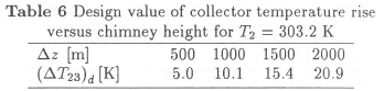
(ΔT23)d/T2 = 1/{cpT2/(gΔz)-1}
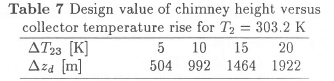
The equation above gives the design value of collector temperature rise for any chosen chimney height.
Since g = 9.81 « 10 m/s2 and cp = 1005 « 1000 J/kgK, the design temperature rise in the collector in degrees K is about 1/100 times the chimney height in metres. It is quite likely that the design temperature rise of about 15 K for a 1500 m high chimney will be exceeded in practice.
If the collector temperature rise is fixed, the design value of chimney height can be found by inverting the equation given above:
(Δz)d = (cpT2/g)/(l+T2/ΔT23)
Table 7 reflects the dependence of design chimney height on collector temperature rise.
The implications of the chosen design condition on the specific power will be derived below.
P2* = (t/c)(l-l/c)-(l-l/C)
= {(t/c)-l}(l-l/c)
P2*d = (cd2/Cd -1) (l - 1/cd)
= cd (1-1/cd2)
= Nd2/(1-Nd)
= Nd2
The equation above draws the attention again to the extreme importance of cycle efficiency and chimney height in determining the plant power per unit mass flow.
The power per unit mass flow is then:
P/m = cpT2nd2/(1-nd)
and the mass flow per unit power is:
m/P = (1-nd)/(cpT2nd2)
For a 250 MW plant and a turbine efficiency of 100 % the required mass flow is:
m250 = (250 X 106) (1 - nd) / (cpT2nd2)
Example values are given in Table 8.
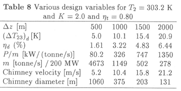
Table 8 shows that a 250 MW plant with T4 = T2 would require a chimney diameter of about 200 m.
Conclusions
An air standard analysis has been done for a solar chimney cycle. The main conclusions are listed below. The conclusions should be read in the context of the assumptions listed at the beginning.
• The cycle efficiency is N) - g Δz/cpT2. It is proportional to chimney height and inversely proportional to collector inlet temperature. Once the chimney is built, the cycle efficiency is virtually cast in concrete.
• There is no optimum combination of cycle pressure ratio and cycle temperature ratio for maximum specific power as in gas turbine cycles. It means that there is no thermodynamic optimum combination of collector size and chimney height.
• The power developed by the plant is P - mg Δz ΔT23/T2. It is proportional to the mass flow, chimney height and collector temperature rise, and inversely proportional to collector inlet temperature.
• The available pressure drop across the turbine is Δpt = P3gΔzΔT23/T2. It is proportional to the turbine inlet density, to chimney height and collector temperature rise and inversely proportional to collector inlet temperature.
• By assuming a value of a pressure loss coefficient, K = 2, and that the maximum power that can be extracted occurs when two-thirds of the pressure drop is across the turbine, the required chimney velocity can be derived as Vc = √(1/3) √{P/m).
An initial design condition where the chimney exit temperature equals the collector inlet temperature is proposed for initial calculations. These conditions enable one to do initial sizing of a plant for a given required power.
• For the proposed design cycle a heat exchanger between chimney exit and collector inlet would not improve specific power (apart from being impractical).
• For the design cycle the maximum power per unit mass flow is approximately proportional to cycle efficiency squared. This implies that although the input energy costs nothing, the cycle efficiency exerts a strong influence through its coupling to specific power and plant capital costs.
• The air standard cycle analysis seems worth while but should be extended with the incorporation of losses. A more realistic model may modify some of the conclusions based on the air standard cycle.
Nomenclature
c compression temperature ratio
Cp specific heat [J/kgK]
D chimney inside diameter [m]
g gravitational acceleration [m/s2]
h enthalpy [J/kg]
K pressure drop coefficient
m mass flow [kg/s]
n polytropic exponent
P power [W]
p pressure [Pa]
r pressure ratio
T absolute temperature [K]
t cycle temperature ratio
V velocity [m/s]
z altitude [m]
Δ change in value
γ specific heat ratio
N cycle efficiency
p density [kg/m3]
Subscripts
c chimney base
d design
opt optimum
t turbine
te turbine exit
1 gas turbine cycle inlet
2 combustor (collector) inlet
3 turbine inlet
4 gas turbine (solar chimney) exit
23 between 2 and 3
Superscripts
* normalized value
' idealised value
References
1. Haaf W, Friedrich K, Mayr G & Schlaich J. Solar Chimneys, Part I: Principle and construction of the pilot plant in Manzanares. International Journal of Solar Energy, 2, pp.3-20, 1983/1984. [ Links ]
2. Haaf W. Solar Chimneys, Part II: Preliminary test results from the Manzanares pilot plant. International Journal of Solar Energy, 2, pp.141-161, 1984/1983. [ Links ]
3. Wilson DG. The design of high efficiency turbomachines and gas turbines. MIT Press, Cambridge, MA, 1984.
4. Cohen H, Rogers GFC Saravanamuttoo HIH. Gas turbine theory. 3rd edn. Longman Scientific and Technical, 1987.
5. Oates GC. Aerothermodynamics of gas turbine and rocket propulsion. Revised and enlarged. AI A A Education series, Washington, 1988.
6. Archer RD & Saarlas M. An introduction to aerospace propulsion. Prentice Hall, New Jersey, 1996.
7. Schlaich J. The solar chimney, electricity from the sun. Edition Axel Menges, Stuttgart, 1995.
8. Stephan K, Schaber K, Körber J, Tamm M & Kim YK. Expert opinion on the thermodynamic modelling of solar chimneys. Institut für Technische Thermodynamik und Thermische Verfahrenstech-nik, University of Stuttgart, 1995.
9. Lenschow DH. Atmospheric flows. In: Johnson RW (ed.). The handbook of fluid dynamics. Springer-Verlag, Heidelberg, 1998.
Received March 1999
Final version December 1999
