



Services on Demand
Journal

Article
 English (pdf)
 Article in xml format
 Article references

 Automatic translation
 Send this article by e-mail
Indicators
Related links
-
 Cited by Google
-
 Similars in Google
Share

 Permalink

Journal of the South African Institution of Civil Engineering
On-line version ISSN 2309-8775Print version ISSN 1021-2019
J. S. Afr. Inst. Civ. Eng. vol.68 n.1 Midrand Mar. 2026
https://doi.org/10.17159/2309-8775/2026/v68n1a1
TECHNICAL PAPER
Calibrated finite element modelling of the progressive structural response of the Yusufeli concrete arch dam during impoundment
RO Cassells; SW Jacobsz; CP Roth
ABSTRACT
Concrete arch dams are complex three-dimensional structures subject to multifaceted loading conditions. Design of concrete arch dams follows an iterative structural analysis approach in which advanced numerical modelling has become the current state-of-the-art tool for analysis. Advancement in the processing power of the personal computer and commercial availability of user friendly and efficient numerical modelling software packages has enabled the development of high-resolution numerical models of arch dams with complex foundation conditions.
The finite element method can be used to create elaborate three-dimensional models of concrete arch dams with complex foundation conditions. The models are however only as reliable as the modelling assumption inputs, particularly the constitutive material modelling parameters. Material testing procedures of the dam concrete and foundation conditions provide a good estimate of the material modelling constitutive parameters, but the inherent variance in these test results and the difference in conditions between site and laboratory, mean these parameters may not necessarily accurately reflect those present under dam operating conditions.
As a result, it is important to validate the material model parameters assumed for the finite element model by calibrating the deformation response of the dam under actual loading conditions. This study examines the validation of a finite element model of the Yusufeli arch dam in Turkey, during reservoir impoundment, by calibrating the computed static deformation response predicted by the model to that of the dam observed from deformation measurement instrumentation.
The model of the dam was shown to be well calibrated by the close comparison between predicted and measured displacement. Results from the model calibration process are discussed and presented, providing insight into the deformation behaviour of a large concrete arch dam during impoundment and the accuracy with which this can be modelled using linear elastic material modelling assumptions.
The calibrated model was used to study the progressive structural behaviour of a large concrete arch dam during impoundment of the reservoir. Due to the inherently favourable structural mode of an arch in compression, it is shown that the stress state of a loaded concrete arch dam is preferable to that of an empty one. These are important considerations to be made during first filling of the dam reservoir.
A comprehensive validation of the modelled stress and strain behaviour of the dam in relation to that measured by stress meters and strain gauges was not achieved due to numerous inconsistencies in measurement data obtained from these instruments.
Keywords: Large concrete arch dams, finite element analysis, numerical modelling validation, dam impoundment, geomechanics
INTRODUCTION
Concrete arch dams are complex hyperstatic civil engineering structures requiring analysis and design by application of advanced mathematical or numerical methods needing computationally expensive numerical analysis techniques. The design of arch dams is not amenable to the application of closed form solutions and usually requires an iterative "trial and error" approach.
The methods used to perform the structural analysis of arch dams have progressed substantially from the early days of arch dam design, using the trial load, membrane theory method or laboratory scale models (ICOLD 1988), to the current state of the art, where advanced numerical modelling techniques are utilised to develop intricate high-resolution models of the dam's behaviour.
The finite element (FE) method is a widely used numerical modelling technique that analyses the behaviour of complex structures by discretising the domain into smaller, interconnected elements. The governing partial differential equations are reformulated through variational principles or weighted residual methods, and within each element the solution is approximated using interpolation (shape) functions. Through the stiffness (displacement) method, these approximations are assembled into a global system of simultaneous algebraic equations, which capture the structural deformation while satisfying displacement compatibility and force equilibrium both locally between neighbouring elements and across the entire structure.
The commercial availability of versatile, user-friendly FE analysis software with pre-programmed FE code, in parallel with the recent advancement in the processing power of inexpensive personal computers, has enabled the development of high-resolution FE models.
Practicing dam engineers can build advanced three-dimensional (3D) FE models of concrete arch dams to accurately simulate and evaluate their behaviour under challenging foundation conditions, where the rock mass strength and stiffness (deformation) properties vary along the dam axis.
Although elaborate FE models can provide valuable insight into the structural response of a concrete dam structure founded on a rock mass with variable material properties along its axis, sound engineering judgement needs to be exercised in setting up and interpreting the computational output of models. Numerical analysis software should be used as a tool to assist the engineer in making design decisions. Even the most advanced numerical analysis software cannot replace the problem-solving ability of experienced engineers, nor should the results they produce always be trusted blindly. The key advantage of FE analysis of dams lies in their realistic demonstration of the actual structural function of an arch dam (Shaw 2015).
The simulated structural function of the dam, as derived from advanced numerical modelling, should be evaluated against the possible dam failure modes when assessing the performance of the structure against evaluation acceptance criteria. Consideration of calculated stresses, strains, and displacements output by an FE modelling analysis of the dam should not be considered in isolation against design criteria.
Elaborate FE models are however only as reliable as the modelling assumption inputs. Various material testing procedures examining concrete used to construct the dam and foundation conditions provide good estimates of the material modelling constitutive parameters, but the inherent variance in these test results and the difference in conditions between site and laboratory mean these parameters may not accurately reflect those present under operating conditions on site (ICOLD 2009). As a result, it is important to validate the assumed FE material modelling parameters by calibrating the deformation response under actual loading conditions. This can be done by conducting a dam impoundment study whereby the measured deformation response of the dam during reservoir impoundment is compared to that predicted by the FE model (Cassells 2025; Cassells et al 2024; Cassells & Shaw 2022). Calibration of an FE model against actual dam behaviour provides the ultimate confidence in the model (Moyo & Oosthuizen 2013).
After construction of the dam is complete, the most critical stage pertaining to dam behaviour monitoring is during impoundment of the water reservoir as the new loads applied by the presence of the reservoir may induce transient stress-strain behaviour (Lombardi et al 2008).
Measurement of the behaviour of the dam during impoundment using instrumentation will provide early warning of unexpected and potentially adverse structural action. Without reference data indicating the expected structural action of the dam during loading, data from instrumentation provides very limited insight. As a result, it is important to validate the assumed material model parameters of the FE model by calibrating its deformation response under actual loading conditions.
Concrete arch dam structural design is a specialist field, of which an in-depth literature review is beyond the scope of this paper. Arch dam design manuals and codes should be consulted to understand the design considerations and approaches adopted in dam engineering (ICOLD 2024; USACE 1994; USBR 1997; FERC 1999).
A comprehensive account of the study outlined in this paper can be found in (Cassells 2025), where extensive discussions of FE modelling and dam design theory is covered.
OBJECTIVE AND SCOPE
The objective of this study was to investigate how accurately the structural behaviour of the Yusufeli concrete arch dam, founded on complex foundation conditions, could be simulated through calibration of an advanced FE model of the dam and foundation. This was achieved by comparison and validation of the simulated behaviour of the Yusufeli Dam FE model against measured behaviour of the dam during first reservoir impoundment. Effectively, the Yusufeli Dam is a prototype large concrete arch dam for which a "digital twin" model was created using the FE method.
Essentially, the calibration process comprised validating the elastic modulus of the dam concrete material. The in-situ elastic modulus of the dam concrete is the parameter in the model expected to have the highest variance about its laboratory tested value (ICOLD 2009), and the parameter to which the deformation response is the most sensitive. The tested deformation modulus of the foundation material is expected to be more reliable as extensive in-situ geotechnical investigations of the rock mass foundation were conducted. It was assumed and retrospectively proven that the global deformation response of the dam is significantly less sensitive to changes in the deformation modulus of the foundation material.
According to Kreuzer and Léger (2013), it has been shown that other modelling parameters such as hydrostatic load and self-weight (density of material) are generally well known and can be practically introduced in the model as deterministic. Conversely it is the variability of elastic modulus of the material that has significant impact on the structural response of the dam, and especially the concrete.
The overall objective was to provide insight into the structural behaviour of a large concrete arch dam under normal and impoundment loading conditions.
METHODOLOGY
The study methodology developed was made up of a suit of analytical tasks listed below:
■ Conducting investigations of the Yusufeli Dam as the prototype dam in terms of its geometrical configuration, construction, design characteristics, and site-specific conditions to obtain a basic understanding of the expected structural behaviour and the implicit mechanisms instigated under loading.
■ Creating a detailed FE model of the Yusufeli Dam and foundation, considering the progressive loading conditions expected to occur during reservoir impoundment.
■ Undertaking a study on the available instrumentation of the dam, followed by a quantitative and qualitative study of the dam behaviour during impoundment to obtain a good understanding of its structural behaviour modes.
■ Calibrating the FE model dam concrete stiffness parameters by comparison of simulated behaviour to measured behaviour.
■ Reviewing the results of the model calibration process and formulating a conclusion on the accuracy of the model and validated dam concrete elastic modulus.
■ Evaluating progressive behaviour of the dam under incremental stages of loading with the aid of the calibrated FE model.
DAM PROTOTYPE
Dam description
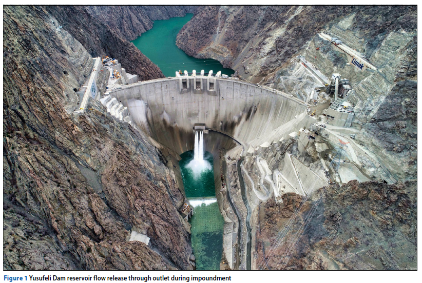
Yusufeli Dam is a 275 m high double curvature concrete arch dam on the Coruh River in the Artvin Province of the Black Sea region of Turkey. The dam has a developed crest length of 540 m and a section thickness of 8 m at the crest and 90 m at the base on the crown cantilever. The dam was constructed with conventionally vibrated mass concrete. The structure contains 4 million m3 of concrete, impounding 2.1 billion m3 of water at full supply level. Yusufeli Dam is the highest dam in Turkey, the fourth highest double curvature arch dam in the world, and ninth highest dam in the world. A photograph of the completed dam structure during reservoir impoundment is shown in Figure 1.
The DSi (Turkish State Hydraulic Works) is the owner of the project. The dam was constructed by Limak Construction S.A. For the detailed and construction design, Limak appointed IC Consulenten of Austria for all geotechnical investigations and design and a team comprising ARQ of South Africa and Su Yapi of Turkey for the dam design. ARQ was responsible for all dam design (IMIESA 2023), which included numerous complex and detailed studies to model all structural loading actions and responses that could be experienced during construction and operation of the dam.
Dam design considerations
The Yusufeli Dam site bedrock comprises variably fractured and sheared igneous rock granites and diabase dykes. The bedrock is intersected by six main discontinuity sets and numerous faults that reflect the regional tectonic setting.
The rock mass foundation is made up of complex interwoven layers exhibiting vertical and horizontal extrusions of material with differing deformation moduli and strength properties. These rock formations contain various faults, joints, and discontinuities, creating local planes of weakness. Highly fractured foundation rock zones exhibit low deformation moduli.
The material design parameters for the various zones of foundation rock mass prior to foundation improvement are shown in Table 1. These material properties were derived from the results of comprehensive geotechnical investigations of the foundation conducted by IC Consulenten of Austria. Extensive consolidation grouting works were undertaken to improve the elastic stiffness of the foundation and reduce the variability in elastic modulus between foundation layers and the cushion concrete. As a result of the grouting, a fair amount of foundation improvement was achieved.
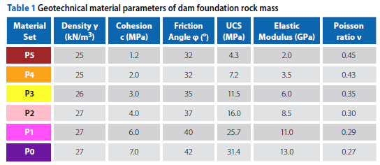
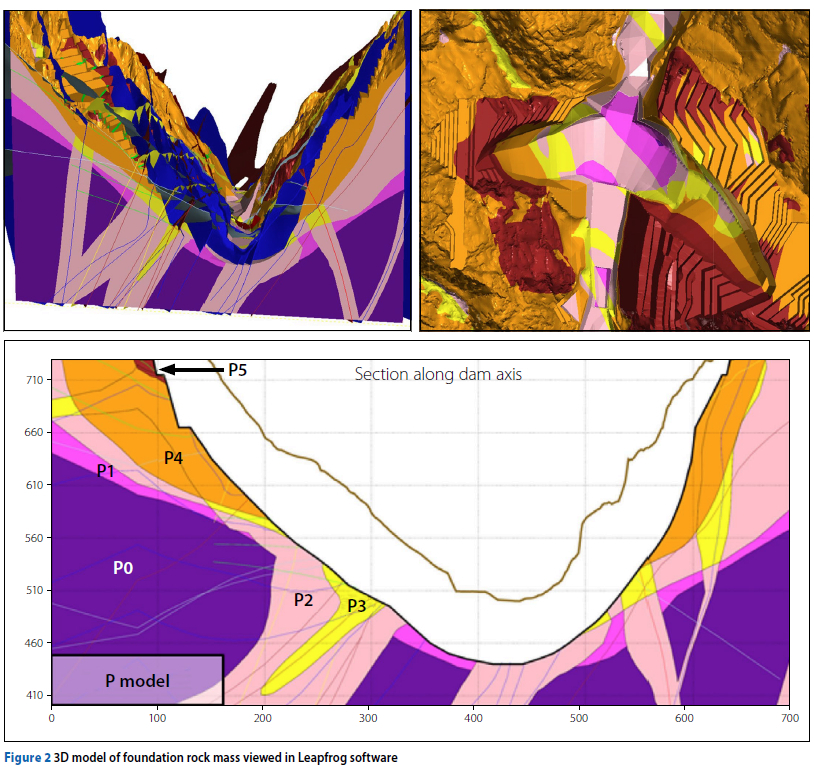
Most of the lower riverbed foundation contains competent rock which has sufficient strength, stiffness and continuity to safely support the structure. The upper abutment materials are of a lower stiffness due to a certain degree of loss of confinement or relaxation. The rock properties of the left and right banks differ from each other, thereby creating an asymmetrical configuration for arch thrust support. The final revision of the 3D model of the rock mass foundation, including the dam excavation, is shown in Figure 2, and the colours of the model correspond to the material types listed in Table 1.
From a design perspective, the dam foundation conditions were the most challenging aspect of ensuring a safe dam structure that complies with all design criteria.
Two primary criteria to be considered for concrete arch dams are the strength and deformability of the foundation rock mass. The rock mass is required to have sufficient compressive and shear strength to resist failure by rupture and sufficient deformation modulus to prevent excessive deformations (Bieniawski & Orr 1976).
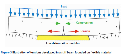
A lower rock mass deformation modulus will not only result in higher overall structural displacements and an increased development of tensions at the heel of the cantilever, but it also causes tensile stress to develop in a radial direction in the concrete at the contact with the rock. This last effect can be understood as similar to the system developed with a rigid beam on a flexible foundation, as seen in Figure 3.
To mitigate the above effect, "cushion concrete" was used as a transition between the stiff dam concrete and the more flexible foundation. Where critical tensions were predicted, the ductility, or concrete tensile strain capacity, of the contact zone was locally enhanced with polymer fibre reinforcement. Several options were tested to identify a means to assure a lower elastic modulus for the "cushion concrete", while retaining other mechanical properties. The application of a high air content (11%) was found to be the most efficient. The cushion concrete was designed for an elastic modulus under sustained load of approximately 12.5 GPa.
The design of a concrete cushion as a low-deformation modulus foundation replacement concrete, to allow smooth stress transfer between the dam and foundation with varying deformation modulus, has been adopted by designers of other super-high concrete arch dams recently completed in China (Song et al 2013).
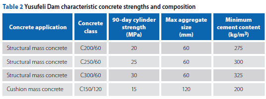
The structural mass concrete of the dam body comprised three different class types, each having different characteristic strengths, for zoning of the dam body. The three concrete designations are shown in Table 2, where the aggregate size and minimum cement content are shown, as well as that for the cushion concrete. The characteristic strength of the dam concrete is defined as the compressive cylinder strength at 90 days.
Dam construction
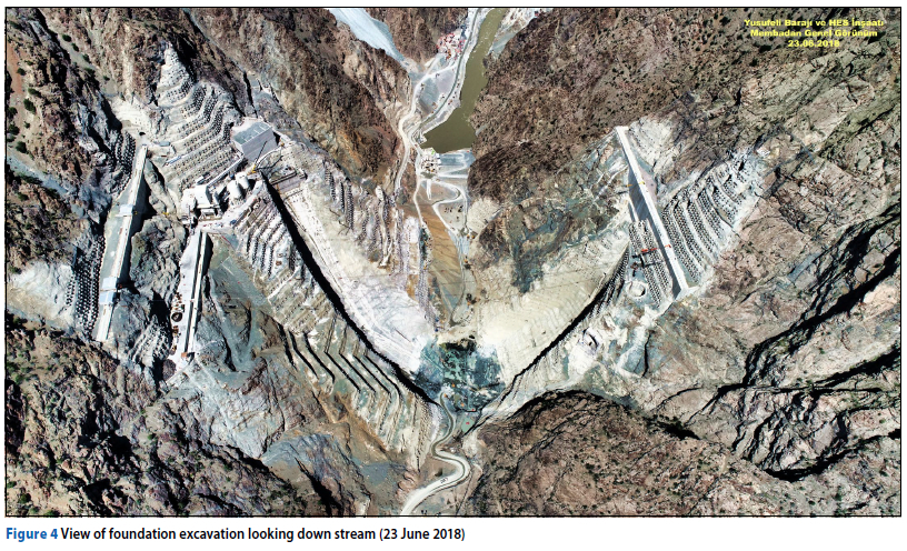
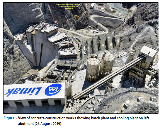
Construction of the Yusufeli Dam commenced in 2013 with early excavation and site access works. Excavation was completed in 2018 (Figure 4) after which concrete works (Figure 5) of the dam body started and was completed in 2021.
Dam impoundment
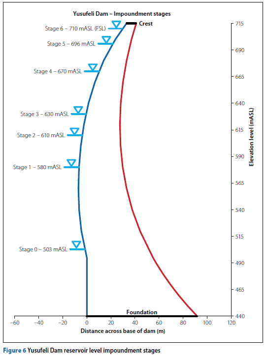
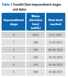
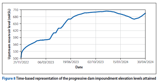
The reservoir impoundment started on 21 November 2022 and was planned to take approximately 2 years, pending the availability of river flow volume and the behaviour of the dam during filling. Water level rise was controlled by release from the Yusufeli outlet works. A reservoir impoundment programme was drawn up, making provision for impoundment stoppages at predetermined elevation heights, allowing for observation of the dam behaviour against expected design behaviour, and to detect any early signs of structural distress or permanent deformation of the dam. The six stages of impoundment stoppages are shown in Figure 6, with Stage 0 being the river diversion level and Stage 6 the full supply level (FSL). At the time of writing this paper in May 2024, the reservoir level had not yet reached FSL and was at 700 mASL. The dates at which the impoundment levels were reached are shown in Table 3.
FE ANALYSIS MODEL
FE mesh
The FE model of the dam was created using the Midas FEA NX software (Midas 2024).
The dam and foundation were modelled as a continuum 3D mesh discretised with a collection of hexahedral, tetrahedral, pyramid, and wedge 3D solid elements. The model is hexahedral dominant, with other elements only used in the vicinity of sharp edges and faces. The dam and foundation FE model is shown in Figure 7 and comprises 330 000 nodes and 786 000 elements.
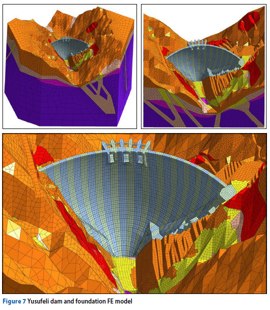
The FE model uses a meshing strategy with a fine mesh of elements for the dam body and the grouted foundation zone in close proximity of dam and a coarser mesh of elements for the outer extents of the foundation. This ensures the model will provide good quality analysis results while also being computationally efficient in terms of analysis time.
The elements within the dam body and immediate foundation zones have regular element shapes with good aspect ratios. This is the zone where large strain gradients were expected to develop. Large element sizes, with less emphasis on good aspect ratio, were used to model the outer extents of the foundation model, where small strain gradients were expected.
Material model assumptions
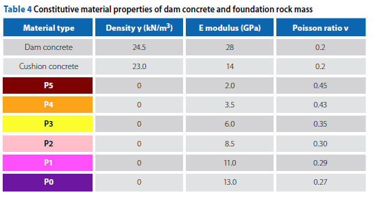
The dam concrete and foundation rock mass material were modelled assuming linear elastic constitutive material parameters, as shown in Table 4. The assumed material parameters of the dam concrete were obtained from laboratory testing of specimens cast and cured in the on-site laboratory under similar conditions to the dam. The assumed parameters for the various zones of rock mass material were derived from the results of the extensive geotechnical investigations of the foundation. The unit weight for the foundation was taken as zero, assuming that the foundation has fully settled under its own weight and any displacement of the dam under gravity is only due to the weight of the dam (Malm 2016; Durieux 2008). The rock mass material sets are colour coded to correspond with the mesh colour of the FE model in Figure 7.
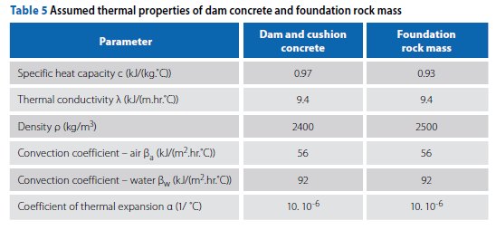
The assumed thermal and thermomechanical parameters of the dam and foundation materials dictate the response of the dam to thermal loading. For purposes of this analysis, thermal loading refers to the change in the temperature state of the dam body due to cyclic seasonal variations in ambient temperature to which the dam is exposed via convection boundaries at the surface of the material. Thermal loading takes the form of heat transfer through a solid medium by conductance and between the solid and the fluid environment (atmosphere and water reservoir) through convection. The thermal and thermomechanical properties assumed for the analysis are shown in Table 5. The thermal and thermomechanical properties of the dam and foundation were assumed to be very similar, as the concrete aggregate was sourced from the local rock material.
Loading conditions
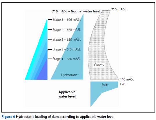
Hydrostatic loading of the dam during impoundment was adopted in the FE model according to the incremental reservoir levels attained at the impoundment stoppage stages. Dam reservoir impoundment stoppages were taken at six intervals, as shown in Figure 6. A time-history plot of the reservoir impoundment progress is shown in Figure 8. The dam foundation level is at 440 mASL, the river diversion level at 503 mASL, the crest of the dam at 715 mASL, and the full supply level 710 mASL.
The hydrostatic loading conditions at each impoundment level comprise gravity, upstream hydrostatic pressure, and actual uplift, as illustrated in Figure 9. Notably, the actual uplift pressure, as measured by piezometers and pressure gauges at the base of the dam, were considered rather than typical design uplift (Casagrande 1961).
For FE modelling purposes, the dam heat transfer problem was approached as a boundary value problem. An initial temperature state of the dam was defined from temperature measurement data at the last point of comprehensive measurement post construction. Seasonal time-varying heat conditions were applied to the dam as thermal contact boundary constraints at the outer faces of the dam and foundation. The heat flow problem was then solved using the FE model according to thermodynamic laws, as governed by the various material thermal parameters and boundary constraints. The operational thermal loading conditions and associated heat flow mechanisms experienced by the Yusufeli Dam during impoundment are shown in Figure 10 and listed below (Andersson & Seppälä 2015):
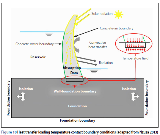
■ Convection of heat between the dry faces of the dam and the atmosphere air
■ Convection of heat between the submerged faces of the dam and the water reservoir body
■ Conductance of heat through the dam body solid
■ Conductance of heat between the dam body and foundation
■ Absorption of heat energy at the dam surfaces exposed to solar radiation from the sun
■ Initial temperature state of dam and foundation just prior to impoundment.
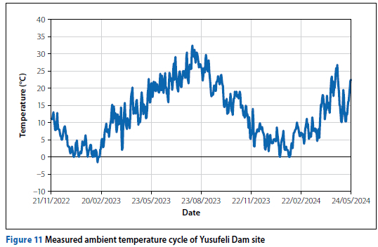
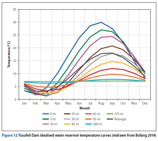
The measured ambient air temperature conditions at Yusufeli Dam from 21 November 2022 to 20 May 2024 are shown in Figure 11. The time-based tem perature state of the dam reservoir water at various depths below the surface was modelled using empirical equations derived from typical reservoir temperature profiles of other large concrete dams, as shown in Figure 12 (Bofang 2014). The various sinusoidal curves of the graph depict the seasonal temperature variation cycles at different reservoir depths.
DAM INSTRUMENTATION
The Yusufeli Dam has a comprehensive set of instrumentation installed within the dam body and surrounding rock mass foundation. Various devices were placed at strategic locations in the dam and its foundation to obtain a comprehensive range of dam behaviour measurements for observing all the relevant forms of behaviour that occur in a loaded concrete arch dam.
The instrumentation installed in the dam comprises the following components:
■ An automated geodetic survey system with beacons on the downstream face of the dam for measuring movement of the dam
■ Hanging and inverted pendulums for measuring relative movement of the dam and foundation
■ Joint meters installed across interfaces between the dam monolith blocks to measure joint opening and closing
■ Piezometers and manometers to measure uplift conditions and the dam-foundation interface
■ Thermocouples to measure the temperature state of dam body.
The monitoring of the dam behaviour during impoundment allows for the detection of possible early signs of distress as the progressively loaded dam displaces, transfers load into the foundation, and seats into its rock mass foundation.
Ultimately, the dam behaviour under impoundment loading should not exceed the expected design behaviour. The ideal scenario entails dam deformation and associated development of stresses/strains marginally below the anticipated design values.
The dam impoundment study was undertaken by considering the cumulative dam behaviour at each of the various reservoir impoundment evaluation stages in comparison to that observed at the impoundment commencement date.
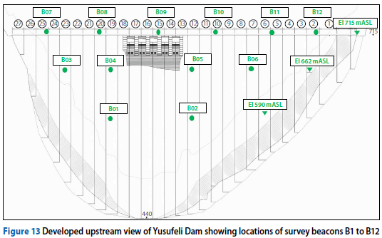
For purposes of calibrating the FE model of dam behaviour during impoundment, the most reliable instrumentation data of the dam was found to be the geodetic survey and pendulum measurements, from which comprehensive time-based deformation behaviour of the dam was deducted. The location of survey beacons B01 to B12 are shown in relation to the dam body in Figure 13.
The Yusufeli Dam has six pendulum devices installed in the central portion of the dam body axis, of which three are hanging pendulums and three are inverted pendulums. One hanging and one inverted pendulum was placed in dam monoliths 13, 16 and 19, respectively. The pendulum device names assigned for the three hanging pendulums are P-13-H-525.5, P-16-H-525.5 and P-19-H-525.5. The inverted pendulums are named P-13-I-525.5, P-16-I-525.5 and P-19-I-525.5. The configuration of the pendulum setup in relation to the dam is shown in Figure 14. Monolith 16 is the crown cantilever of the dam.
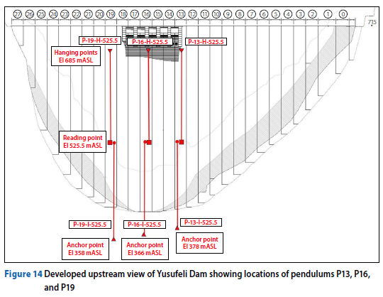
The suspension points of the hanging pendulums were positioned in the dam gallery, 30.5 m below the crest of the dam at elevation 684.5 mASL. The anchor points for the inverted pendulums of monoliths 13, 16, and 19 were fixed in the foundation rock mass below the dam base at elevation levels 378 mASL, 366 mASL, and 358 mASL, while the deepest foundation level of the dam is at 440 mASL. The reading points of both the hanging and inverted pendulums are located in the gallery at dam elevation 525.5 mASL.
The hanging pendulums measure the radial and tangential rotational movement of the top of the dam in relation to the lower portion of the dam. The inverted pendulums measure the relative movement of the lower portion of the dam with reference to the foundation below.
COMPARISON OF PREDICTED AND MEASURED HORIZONTAL DISPLACEMENT
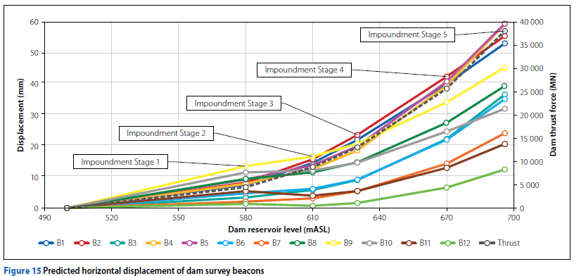
The predicted (modelled) resultant horizontal displacement of the dam survey beacons through impoundment stages 1 to 5, as a function of reservoir elevation level, is shown as a suite of curves in Figure 15. The points on the curve represent predicted values at the various stages of reservoir impoundment, while the lines plotted between the points are interpolations between these values. The maximum displacement predicted after five stages of impoundment is approximately 59 mm, occurring at survey beacons B4 and B5. The incremental resultant dam thrust force is also plotted on the secondary vertical axis in the figure by the dashed black line.
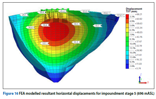
The displacement plot extracted from the FE analysis results for impoundment stage 5 is shown in Figure 16, where positive displacement denotes movement towards the downstream side (reservoir level at 696 mASL - dark line in figure). The maximum horizontal displacement of the dam crown (centre) cantilever at this stage was predicted to be 69 mm at elevation 638 mASL. The interrogated outputs on the plot indicate predicted displacement values at the dam survey beacon locations.
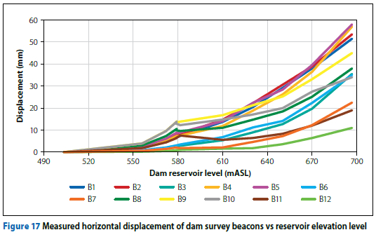
The measured horizontal displacement of survey beacons 1 to 12, as a function of the reservoir impoundment levels, are shown in Figure 17. In most cases the differences between measured and modelled dam displacement response do not differ by more than 10% of the measured value. Considering that a modern geodetic survey system can measure deformation movements to an accuracy of 2 mm (Pretorius et al 2001), the displacement of the dam is very well simulated by the FE model.
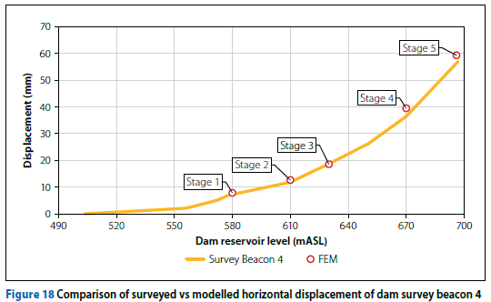
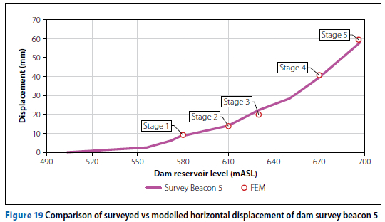
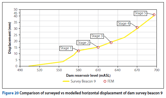
A direct comparison of the measured and modelled displacement behaviour of the dam for survey beacons 4, 5 and 9 are shown in Figures 18, 19 and 20. The measured displacement of the beacon during impoundment is represented by continuous curves, while the modelled displacement for the various impoundment stages is shown by red circular points.
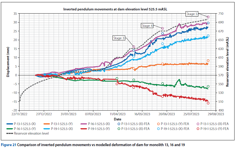
A comparison of the measured and predicted radial (X) and tangential (Y) movement of the inverted pendulums installed in the dam for impoundment stage 3, 4 and 5 are shown in Figure 21. Due to very small pendulum measurements at stage 1 and 2, these values were ignored for calibration. The plotted curves indicate the pendulum movements with time, while the circular points indicate the predicted pendulum movements at impoundment stages 3, 4 and 5. Positive radial displacements indicate movement towards the downstream side, while positive tangential displacements denote movement along the axis to the right abutment. If properly maintained and operated, pendulums can produce measurements to an accuracy level of 0.5 mm (Dunnicliff 1988).
A comparison summary of the measured vs predicted displacement values of the dam for stage 5 of impoundment is shown in Table 6 and plotted comparison bars are depicted in Figure 22. The comparison shows that, on average, the modelled displacements are within 1.1 mm greater than the measured value.
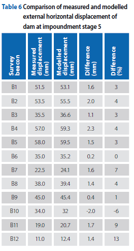
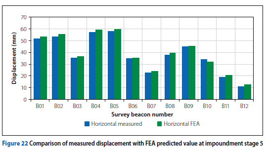
The average difference between modelled and measured displacements of the dam is 4%, showing the model marginally overpredicts the dam deformation behaviour at impoundment stage 5 and is thus conservative.
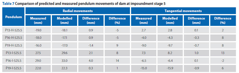
A comparison summary between the measured and modelled pendulum movements at impoundment stage 5 is shown in Table 7. The measured relative displacement of the dam is well modelled with most differences being within 2 mm or 10% of the measured value. Pendulum measurements at earlier stages were very small and not considered reliable enough for calibration due to the small values in relation to instrument accuracy.
Other model calibration results indicated that measured movement across monolith joints were modelled to within a value of 0.5 mm, while measured dam body temperatures were modelled to within 1.5°C of those measured by the thermocouples. A comprehensive validation of the modelled stress and strain behaviour of the dam in relation to that measured by stress meters and strain gauges was not achieved due to numerous inconsistencies in measurement data obtained from these instruments.
OUTCOME OF FE MODEL CALIBRATION
It has been shown that the deformation behaviour of the dam is well modelled by the calibrated FE model. The model was thus used to conduct comprehensive behavioural analyses of the progressive structural behaviour of the dam during impoundment.
INTERPRETATION OF VALIDATED PROGRESSIVE DAM BEHAVIOUR
Calculated horizontal displacement of crown cantilever
A summary of the distribution of computed resultant horizontal deformation results of the dam along the height of the crown cantilever for the various impoundment stages is shown in Figure 23. The progressive deformation curves indicate how the maximum point of deformation along the height of the dam moves upwards towards the crest as the reservoir elevation level rises. The maximum deformation at stage 5 of the impoundment programme occurs at elevation level 640 mASL, which is approximately 70% of the dam height from the base. This is noted since, at Stage 5, the reservoir elevation level of 696 mASL is still 19 m below the crest and 14 m below the normal operating elevation or FSL.
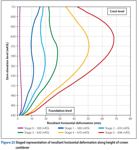
The impact of the ambient thermal loading conditions is evident as the crest portion of the dam (elevation 615 mASL to 715 mASL) is seen to displace downstream during the winter period and upstream during the summer period. The cooling of the dam and associated contraction/shrinkage causes it to deflect downstream, while the warming of the dam and associated expansion causes it to move upstream. The winter period coincides with impoundment stage 1 and the summer period with stages 4 and 5. Stages 0, 2 and 3 are reached mid-season. The upper portion of the dam is more sensitive to ambient temperature changes due to the thinning of the dam width towards the crest. The thicker potion of the dam near the base has a larger thermal inertia.
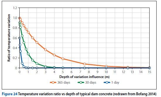
For a mass concrete structure, the depth below the surface that is influenced by external ambient temperature variations is exponentially proportional to the time period of the temperature variations. Generally, only the outer 6 m to 7 m shell of concrete on the upstream and downstream face of a large dam experiences a significant variation in the annual temperature state, with less than 10% of the ambient temperature variation amplitude between winter and summer penetrating further than 7 m beneath the surface face (Bofang 2014).
Curves representing the temperature variation ratio vs depth beneath the concrete surface for different temperature variation time periods is shown in Figure 24. It is also noted from the curves of Figure 24 that less than 10% of daily ambient temperature variation penetrates further than 0.3 m beneath the surface of a concrete dam. Consequently, a 20°C surface temperature variation would result in a variation of less than 2°C, at a depth of 0.3 m beneath the surface.
Horizontal displacement in plan
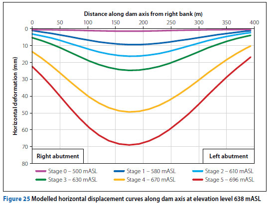
The modelled horizontal displacement for the various impoundment stages along the dam's axis at elevation level 638 mASL is shown in Figure 25. The curves depict the significant increase in horizontal displacement towards the downstream side, especially at the central portion of the arch where the maximum displacement approaches 70 mm at stage 5 of impoundment. The curves also indicate the relative symmetry in the deformed shape of the arch.
Calculated vertical stress development upon impoundment
Figure 26 illustrates the progressive development of vertical stresses along the height of the crown cantilever at the dam's upstream face for the various reservoir impoundment levels. The series of curves are relatively smooth with the exception of two significant slope changes at elevation 495 mASL and 675 mASL respectively, where the dam experiences distinct changes in geometrical stiffness of the cantilever in the vertical plane.
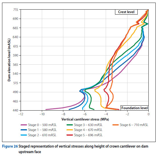
At elevation 495 mASL the upstream face of the dam experiences a discrete change in profile from a vertical to curved surface. This is the point where the curvature of the vertical plane of the dam commences, progressing upwards and forming the undercut of the dam. Between elevation 665 mASL and 685 mASL the geometrical stiffness reduces due to the openings of the spillway.
The vertical stress distribution shows that the upstream face of the dam remains in vertical compression through all stages of reservoir impoundment. After construction of the dam and prior to hydrostatic loading from the reservoir, the dam structure leans backwards and the heel of the dam experiences significant vertical compressive stresses, decreasing along the height of the dam to approximately zero at the crest. As the reservoir level rises, the increasing hydrostatic load pushes the dam forward and into its abutments, causing the cantilever to rotate and deflect downstream.
During the advanced stages of impoundment (stage 4 to 6), the vertical compression stress at the lower portion of the dam has decreased significantly in comparison with the early stages (stage 0 to 3). The vertical compression stress at the heel of the dam is shown to decrease from approximately 9 MPa to 3 MPa.
It is noted that significant vertical compressive stress develops mid-height of the dam at the advanced stages of impoundment from around 1 MPa to 3 MPa. This is caused by vertical hydrostatic loading of the arch curvature in the vertical-radial plane of the dam, and occurs when the reservoir level rises above the inflection point of the vertically curved upstream face. This observation depicts the effective behavioural functioning of the double curvature of the arch in keeping the concrete in compression during hydrostatic force transfer from reservoir to foundation. Single curvature arch dams do not exhibit this favourable form of structural behaviour.
The progressive vertical stress development in the dam downstream face along the height of the crown cantilever is shown in Figure 27 for the various impoundment reservoir levels. The series of stress curves are relatively smooth, showing that the downstream face remains in vertical compression from commencement of dam filling to the point when the reservoir reaches the FSL.
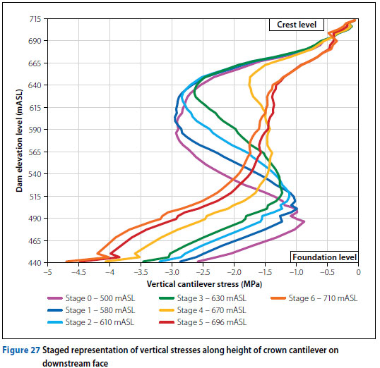
The vertical compression at the toe of the dam increases from a stress value of 2.5 MPa to 4.5 MPa during the term of impoundment as the dam is seen to lean progressively forward as it takes up the rising hydrostatic load.
The vertical stresses expected to develop just above mid-height of the dam have significant compressive stresses of 2 MPa to 3 MPa during the early stages of impoundment. These stresses are induced by the vertical gravity loading of the concrete as a result of the overhang of the upper portion of the arch structure. The rising reservoir level and associated increase in hydrostatic load cause the vertical cantilever action of the downstream deflecting central arch to transition from a free vertical cantilever to a propped cantilever, whereby the stiffening effect of the cross-loaded horizontal arch units acts as series of supporting elastic springs. This analogy was demonstrated by Zimbabwean arch dam designer Wild (1980) and illustrates a further advantage of the double curvature arch.
The propped cantilever structural mode of the downstream deflecting dam causes a hogging moment to develop in the region of the propped elastic support, inducing tension, reducing the vertical precompression of the overhang from between 2 MPa and 3 MPa to less than 1.5 MPa.
Calculated horizontal (axial) stress changes upon impoundment
The set of horizontal (axial) stress curves plotted in Figure 28 indicate the sequential horizontal arch stress development along the height of the crown cantilever along the upstream face of the dam. Prior to hydrostatic loading of the dam, the dam leans back under its own weight and the horizontally spanning arch units undergo elongation and an increase in aperture angle.
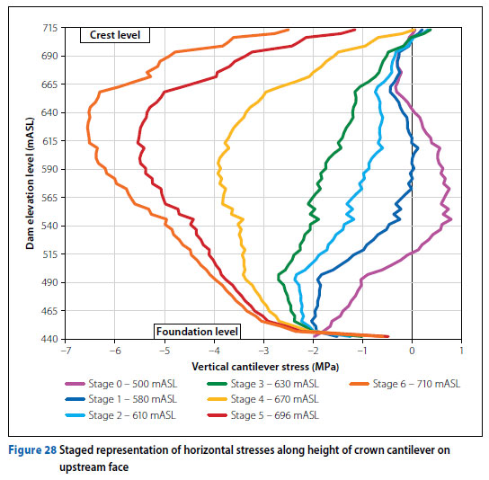
This induces the development of horizontal tensions as the arches effectively hang back (towards the upstream) from their abutment supports. The purple curve in the plot shows the midsection of the dam initially subject to horizontal tensile stress, ranging from 0 MPa to nearly 1 MPa.
During filling of the reservoir, the horizontal arch units gradually develop horizontal compressive stresses along their axes. At stage 6 of the impoundment process, significant compressive horizontal stresses of more than 6 MPa develop at an elevation level of 630 mASL, i.e. at approximately 70% of the dam height above foundation. At this height, the horizontal stiffness of the arch units is greater than the vertical stiffness of the cantilever unit, resulting in horizontal load transfer of the hydrostatic forces into the abutments. The horizontal compressive arch stress of the dam at FSL (stage 710 mASL) decreases significantly along the height of the dam from 70% height to the crest as the hydrostatic load decreases. Despite the zero hydrostatic load at the crest of the dam, the dam still develops a substantial horizontal compression stress of 2.5 MPa at the crest. This indicates that, although the vertical stiffness of the cantilever is relatively low, it is still sufficient to transfer hydrostatic load vertically across arch units to the arch unit at the crest of the dam.
The set of horizontal (axial) stress curves in Figure 29 indicate the sequential horizontal arch stress development along the height of the crown cantilever on the downstream face of the dam. The progressive horizontal stress behaviour on the downstream face is similar to that of the upstream face, except for the lower portion of the dam where increasing hydrostatic load decreases the horizontal compressive stress.
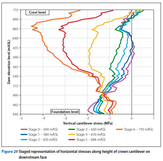
The horizontal arch units at the bottom of the dam have a small radius - i.e. high curvature - and the horizontal displacement of these arches towards the downstream side causes the arch to open up on the concave side, reducing the curvature and increasing the radius. Effectively, the lower arches have a greater bending stiffness than the upper arches, meaning a significant portion of the load near the toe of the arch dam is transferred by rotation as opposed to axial thrust, which is seen to occur at the upper, more flexible arches. Bending of the lower arch units under increased hydrostatic loading induces marginal horizontal tensile stresses (bursting stress), which effectively reduces the precompression horizontal stress that develops under lower hydrostatic loading experienced at early stages of impoundment. The horizontal compressive stress in the lower portion of the arch decreases from approximately 2 MPa to 1 MPa during impoundment.
Minor principal stress changes
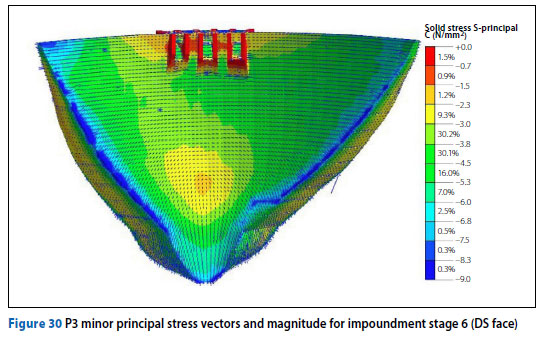
The maximum equivalent compressive stresses in an arch dam under FSL reservoir loading conditions normally develop at the toe of the dam along the lower abutments. This is the part of the arch where the vertical compressive cantilever force vectors and horizontal compressive arch force vectors converge and meet, as shown in Figure 30 by the dark blue contour in the principal stress plot. The compressive minor principal stress that develops in the Yusufeli Dam at the toe along the lower abutments ranges from 7 MPa to 9 MPa during the advanced stages of impoundment.
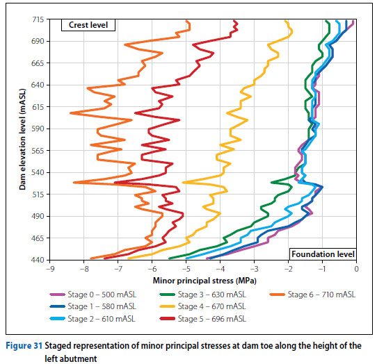
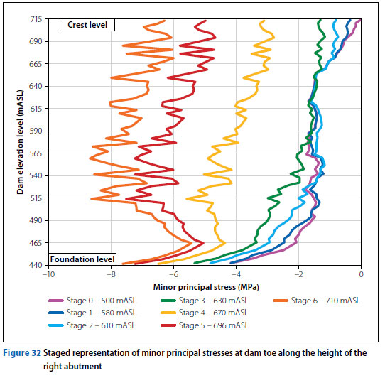
The progressive minor principal stress development in the dam toe along the height of the left abutment is shown in Figure 31 for the various impoundment reservoir levels. The series of stress curves are relatively jagged due to the re-entrant corner FE modelling phenomenon between dam toe and foundation abutment, causing localised stress concentrations to be computed (Logan 2019; Durieux & van Rensberg 2016). Notwithstanding the localised high/low points along the stress curves, the overall average form of the curve is evident. The similar development of stresses along the toe of the right abutment is shown in Figure 32.
Change in stress state upon impoundment
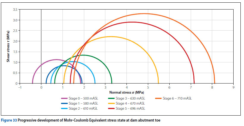
To illustrate the development of the complete stress state at the downstream dam toe during the various stages of reservoir impoundment, a sequence of Mohr circles is presented in Figure 33. The Mohr circles show the evolution of both the major and minor principal stress as loading progresses, with the radius resenting the maximum induced shear stress. The major principal stress changed from tensile to relatively small compressive stresses upon impoundment but were overshadowed by the large change in the minor principal stress upon impoundment as a compressive stress state rapidly developed upon filling. The associated rise in the major and minor principal stresses keeps the induced shear stresses moderate and demonstrates the inherent structural strength of an arch structure, which is a result of its geometrical shape and favourable mode of load transfer.
This observation confirms the well-known premise that a loaded concrete arch dam is safer than an unloaded one.
DISCUSSION OF RESULTS AND CONCLUSION
A comparison between the measured and modelled behaviour of the Yusufeli Dam showed that generally all predicted deformations were no more than 5% to 10% greater than the measured deformation of the dam. This demonstrates very good correlation between the predicted and measured deformation behaviour, confirming the accuracy of the dam and foundation FE model developed for Yusufeli Dam, assuming linear elastic material properties.
The fact that the predicted displacements are close to those measured, but generally exceed the measured values, furthermore confirms the excellent behaviour of the dam structure during the reservoir impoundment and that the model is marginally conservative and realistic.
The deformation response of the dam to hydrostatic loading is sensitive to the dam concrete elastic modulus value, and this is the primary parameter considered for calibration of the dam FE model against measured behaviour during impoundment.
A set of behavioural analyses undertaken on the calibrated dam FE model allowed for observations to be made in terms of the dam response to changes in reservoir level and temperature loading conditions.
Noteworthy observations made of the modelled and measured dam behaviour during the incremental loading stages of impoundment are summarised below:
■ The design uplift pressure assumed for a concrete dam is normally conservative in comparison to actual uplift pressure if the drainage curtain and internal drain system is functioning properly.
■ The geodetic survey of dam displacement behaviour is the most reliable form of dam displacement monitoring.
■ Pendulums, more specifically hanging pendulums, are the most sensitive deformation measurement devices to be installed in a dam, and their proper maintenance and operation is critical. If properly used, these devices can have an accuracy of 0.5 mm when measuring dam deformation, but practically this is often not the case due to external interference from wind in the shaft, water condensation and resulting dripping, spider webs, and general bumping of the device by technicians.
■ The geometric non-linear relationship between the rising reservoir level and the hydrostatic load, paired with the increased flexibility of the arch towards the crest, results in a large portion of the dam deformation occurring towards the end of the reservoir impoundment process.
■ The development of the Mohr-Coulomb stress state at the toe of the dam during the various stages of hydrostatic loading during impoundment illustrate the rapid development of a fully compressive stress state, effectively demonstrating how a hydrostatically loaded arch dam is safer than an unloaded empty dam.
■ Generally, only the outer shell of the dam is significantly responsive to changes in ambient temperature conditions, and the core temperature state remains relatively stable after dissipation of the heat of hydration.
■ The structural mode of a loaded arch dam is normally described as system of interacting cantilevers and arches transferring loads to the foundation and abutments. The configuration of the system of cantilever and arch units that develops within the loaded dam is dependent on the hydrostatic loading conditions.
■ Comprehensive validation of the modelled stress and strain behaviour of the dam in relation to that measured by stress meters and strain gauges was not achieved due to numerous inconsistencies in the measurement data obtained from these instruments.
ACKNOWLEDGEMENT
The lead author thanks Dr Quentin Shaw, Principal Dam Designer for the Yusufeli Dam, for his invaluable mentorship and guidance in dam design. The lead author also thanks the dam owner, the DSi, and their representative the General Directorate Dincer Aydogan for permission to publish this article. Thanks and appreciation are also extended to the client Limak Inşaat A.Ş. and their representative Fatih Çevik, for support and cooperation throughout the project.
REFERENCES
Andersson, O & Seppälä, M. 2015. Verification of the response of a concrete arch dam subjected to seasonal temperature variations. Master's dissertation, KTH Royal Institute of Technology, Sweden. [ Links ]
Bieniawski, Z T & Orr, C M. 1975. Rapid site appraisal for dam foundations by the geomechanics classification. Proceedings, 12th ICOLD Congress, 29 March - 2 April, Mexico City, Mexico, pp 483-497. [ Links ]
Bofang, Z. 2013. Thermal stresses and temperature control of mass concrete. Butterworth-Heinemann. [ Links ]
Casagrande, A. 1961. Control of seepage through foundations and abutments of dams. Geotechnique, 11(3):161-182. [ Links ]
Cassells, R O. 2025. Validated numerical modelling of the tructural response of a super-high concrete arch dam during impoundment. Master's dissertation, University of Pretoria, South Africa. [ Links ]
Cassells, R O, Shaw, Q H W, Çevik, F V & Aydogan, D. 2024. Calibrated numerical modelling of the stress-strain response of the 275 m high Yusufeli concrete arch dam during first filling. Proceedings, 92nd ICOLD International Symposium, 29 September - 3 October, New Delhi, India. [ Links ]
Cassells, R O & Shaw, Q H W. 2022. Validated numerical modelling of the stress-strain response of a super high concrete arch dam. Proceedings, 2022 SANCOLD Conference, 9-11 November, Johannesburg, South Africa. [ Links ]
Dunnicliff, J. 1988. Geotechnical instrumentation for monitoring field performance, 1st edn. John Wiley & Sons. [ Links ]
Durieux, J H. 2008. Development of a practical methodology for the analysis of gravity dams using the non-linear finite element method. Master's dissertation, University of Pretoria, South Africa. [ Links ]
Durieux, J H & Van Rensburg, B W J. 2016. Development of a practical methodology for the analysis of gravity dams using the non-linear finite element method. Journal of the South African Institution of Civil Engineering, 58(2):2-13. [ Links ]
FERC. 1999. Chapter 11 Arch Dams. In: Engineering guidelines for the evaluation of hydropower projects. Washington DC: Federal Energy Regulatory Commission. [ Links ]
ICOLD. 2025. The physical properties of hardened conventional concrete. In ICOLD Bulletin 145. [ Links ]
International Commission on Large Dams. [ Links ]
ICOLD. 1988. Development of Dam Engineering in the United States, 1st edn. New York: Pergamon Press. [ Links ]
ICOLD. 2024. Arch dam design: Structural analysis methodologies and criteria. In ICOLD Bulletin. Paris: International Commission on Large Dams. [ Links ]
IMIESA. 2023. Turkey's Yusufeli Dam is one of history's most iconic structures. IMIESA, 48(8): 16-19. [ Links ]
Kreuzer, H & Léger, P. 2013. The adjustable factor of safety: A reliability-based approach to assess the factor of safety for concrete dams. International Journal on Hydropower and Dams, 20(1):67-90. [ Links ]
Logan, D L. 2019. A first course in the finite element method, 6th edn. Boston: Cengage. [ Links ]
Lombardi, G, Amberg, G & Dabree, G R. 2008. Algortihm for the prediction of delays in behaviour of concrete dams. The International Journal of Hydropwoer and Dams, 15(3):111-116. [ Links ]
Malm, R. 2016. Guideline for FE analysis of concrete dams. Engiforsk AB. [ Links ]
Midas. 2024. FEA NX User Manual. Korea: MidasSoft Inc. [ Links ]
Moyo, P & Oosthuizen, C. 2013. Structural health monitoring of arch dams using dynamic and static measurements. WRC Report No. 2025/1/13. Water Research Commission. [ Links ]
Nzuza, M H S. 2013. Thermo-mechanical modelling of arch dams for performance assessment. Master's dissertation, University of Cape Town, South Africa. [ Links ]
Pretorius, C J, Schmidt, W F, Van Staden, C S & Egger, K. 2001. The extensive geodetic system used for the monitoring of a 185 m high arch dam in Southern Africa. Proceedings, 10th FIG International Symposium on Deformation Measurements, 19-22 March, California, USA, pp 203-2013. [ Links ]
Shaw, Q H W. 2015. The structural function of different arch dam types. Proceedings, 2015 SANCOLD Annual Conference, 1-3 September, Cape Town, South Africa. [ Links ]
Song, S, Feng, X, Rao, H & Zheng, H. 2013. Treatment design of geological defects in dam foundation of Jinping I Hydropower Station. Journal of Rock Mechanics and Geotechnical Engineering, 5(5): 342-349. [ Links ]
USACE. 1994. EM 1110-2-2201 Arch Dam Design. Washington, DC: United States Army Corps of Engineers. [ Links ]
USBR. 1977. Design of arch dams: Design manual for concrete arch dams. Colorado: United States Department of Interior Bureau of Reclamation. [ Links ]
Wild, R M. 1980. The design of small arch dams in wide U-shaped valleys. Zimbabwe Engineer, 12: 293-297. [ Links ]
 Correspondence:
RO Cassells
ARQ Consulting Engineers, Lynnwood Manor
Pretoria 0081, South Africa
ryan@arq.co.za
SW Jacobsz
Department of Civil Engineering, University of Pretoria
Hatfield, Pretoria 0002, South Africa
sw.jacobsz@up.ac.za
CP Roth
Department of Civil Engineering, University of Pretoria
Hatfield, Pretoria 0002, South Africa
chris.roth@up.ac.za

RYAN CASSELLS (Pr Eng) is a structural dam engineer at ARQ Dams in Pretoria. He holds a master's degree in civil engineering from the University of Pretoria and is registered as a professional engineer with ECSA. Ryan has extensive experience in the analysis and design of large concrete dams. His expertise lies in applying advanced numerical modelling techniques to understand structural behaviour and to develop practical, efficient solutions to complex engineering challenges. He is a member of SANCOLD and serves as South Africa's representative on ICOLD Technical Committee A - Computational Aspects of Analysis and Design of Dams.

PROF SW JACOBSZ (Pr Eng, FSAICE) is a Professor in the Department of Civil Engineering at the University of Pretoria. Although specialising in geotechnical engineering, he also works in the field of instrumentation and the monitoring of civil engineering structures like tailings dams, embankments and bridges. He has been involved in the monitoring of a number of full-scale structures and large-scale field trials both in Southern Africa and the United Kingdom.

PROF CHRIS ROTH (Pr Eng, ESAiCE) is an Associate Professor in Civil Engineering at the University of Pretoria, working in the discipline of structural engineering. He started his career in consulting engineering before joining the University of Pretoria, and is the current chairman of SANS Technical Committee98-Structurai and geotechnical design standards. He obtained a BEng degree in civil engineering at the University of Stellenbosch, and an MS and PhD at Cornell University. His interests are in structural reliability and structural analysis. He is serving as President of SAiCE in 2026.