Services on Demand
Article
 English (pdf)
 Article in xml format
 Article references
Indicators

Related links
-
 Cited by Google
 -
 Similars in Google
Share

 Permalink
R&D Journal
On-line version ISSN 2309-8988
Print version ISSN 0257-9669
R&D j. (Matieland, Online) vol.1 Stellenbosch, Cape Town Feb. 1985
Multiobjective Design of an Antisymmetric Angle-Ply Laminate by Nonlinear Programming
S. Adali*
CSIR, Pretoria
An antisymmetrically laminated angle-ply plate is optimized with the objectives of minimizing the maximum dynamic deflection, maximizing the natural frequencies and/or maximizing the buckling load. The design variables are the fiber orientation and the thickness of individual layers and are computed by using the methods of nonlinear programming. The concept of Pareto optimality is used in formulating the design problem and in reducing the multiple objectives into a single performance index. Numerical results are presented in the form of optimal tradeoff curves which allow the designer to assess the various possibilities open to him before deciding on a certain design. In this sense, the present design is an interactive process.
Introduction
Multiobjective design of a structural element becomes a necessity when the element works under more than one loading condition during its service life. In such a case, the designer is faced with the problem of satisfying a number of conflicting objectives with a single design which should meet all the design requirements in the best possible way. To solve such a problem, the designer should first find out about the best capabilities of the structure in question in terms of its performance with regard to the specified objectives under different loadings. The designer, finally, chooses a certain design after consideration of various possibilities open to him. In this sense a multiobjective design is an interactive process in which the designer seeks a compromise solution.
In the present paper, we optimize an antisymmetrically laminated angle-ply plate with respect to the maximum dynamic deflection, natural frequencies, and the buckling load. The design variables are the fiber orientations and the thickness of the layers which form the laminate. The objectives of the design are the minimization of the maximum deflection when the plate is acted upon by a harmonic excitation, the maximization of the natural frequencies, and the maximization of the buckling load. The plate is taken to be rectangular and simply supported. The concept of Pareto optimality is used in the design, which seems to be a natural and physically meaningful extension to single purpose optimal design.
Previous work on the optimal design of composite plates has mostly been on symmetric laminates for which the coupling stiffnesses vanish [1-11]. The design of antisymmetrically laminated plates was determined with the objective of increasing the uniaxial or biaxial buckling loads [12, 13].
Optimization problem is formulated as a nonlinear programming problem and solved by using a quasi-Newton algorithm for finding a minimum of a function, subject to upper and lower bounds on the independent variables, using function values only [14]. The program is available as a NAG library routine from the Numerical Algorithms Group of England. For a discussion on the convergence of the method, the reader is referred to [15]. The numerical results are given for a laminate made of a carbon fiber reinforced epoxy plastic material and are presented in the form of optimal tradeoff curves which represent the points of optimum plate response.
Problem Formulation and Solution
We consider a simply supported rectangular plate of length a, width b, and composed of an even number of anisotropic laminae, each of which is oriented at an angle of 0k on one side of the middle surface with the corresponding equal thickness lamina oriented at an angle of - 6k on the other side (Fig. 1). Each layer possesses a plane of elastic symmetry parallel to the middle surface and is of constant thickness hk. Such plates are commonly known as antisymmetric angle-ply laminates. The XYZ coordinate system and displacement components U, V, and W in these directions are shown in Fig. 1. The linearized equations of motion of the laminated plates are available in literature [16, 17] and for the antisymmetric angle-ply laminates the displacement equations are
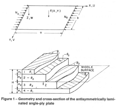
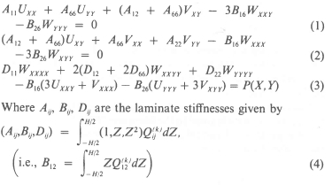
with Qij(k) denoting the plane stress reduced stiffness components of the kth layer given in Appendix and H the total thickness of the plate. We note that the notation of [17] is used throughout the paper. In equation (3), P{X, Y) = pλ20W + F{X, Y) when a forcing function eiλ0t F(X,Y) is applied on the plate; P(X, Y) = pΩ2W when the plate undergoes free vibrations with frequency Ω; and P(X,Y) = -N0WXX when a buckling load N0 in the X-direction acts on the plate. We note that in equations (1-3), the body forces and the inplane and rotary inertia terms are neglected. For the simply supported plate, the differential equations (1-3) are subjected to the boundary conditions
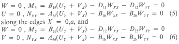
along the edges Y = 0,b where Mn is the resultant bending moment normal to the n-direction and N„, is the resultant normal force normal to the n-direction and parallel to the t-direction.
We introduce the following dimensionless quantities:
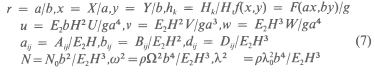
where g = maxxy F{ax,by)\ Hk is the thickness of kth layer; and E2 is the transverse modulus of elasticity of the material.
By substituting (7) into (1-3) we obtain the nondimensional form of the governing equations which are given in the Appendix.
The multiobjective design problem consists of determining the optimal fiber orientation 0k and the thickness hk of the kth layer where k = 1,2 . . . ,K, with Κ denoting the number of layers so as to satisfy the following objectives:
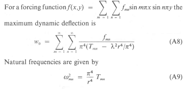
(a) minimization of the maximum deflection w0 when the plate is acted upon by the load f(x,y) with the forcing frequency λ,
(b) maximization of the natural frequencies ω of any given order when the plate undergoes free vibrations, and
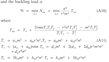
(c) maximization of the buckling load Ν when the plate is subjected to an inplane load N.
We note that due to antisymmetry we have 0k = - θκ _ k +1 and hk = hK_k +1. Moreover, the design variables should satisfy the constraints
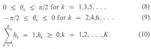
Due to the antisymmetry requirements and the constraint (10), which, in effect, eliminates one thickness variable, the number of effective design variables is K-1 of which K/2 are 0k's and (K/2) - 1 are hk's.
The explicit solutions of the bending, free vibration and buckling problems are obtained in the literature [16, 17] by the method-of separation of variables and by expanding the load ƒ into the double Fourier series
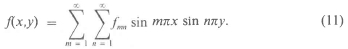
The displacement functions are given by
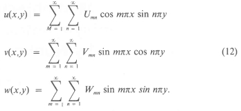
The values for the maximum deflection w0, natural frequencies ωmn, and the buckling load Ν are given in the Appendix. We note that the maximum deflection w0 is given by a finite series if f(χ,γ) in (11) can be expressed in a finite number of terms. In the sequel, we illustrate the design procedure by considering such a case in one of the examples.
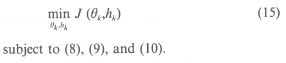
Now the design problem can be stated as a mathematical programming problem in the following form:
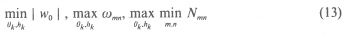
subject to the constraints (8-10) with k = 1,2, . . .,K/2. Here wQ, ωmn, and Nnm are given by (A8), (A9), and (A10), respectively. We note that each of the optimization problems in (13) comprises a nonlinear programming problem due to the dependence of the expressions for w0, wmn, and Nmn on the design variables 0k and hk in a nonlinear manner.
Pareto Optimality
The objectives of the present design problem are three-fold:
(a) the minimization of the maximum dynamic deflection,
(b) the maximization of the natural frequencies, and
(c) the maximization of the bucking load.
Ideally, we wish to determine a set of design variables {0k, hk} which would simultaneously achieve all these objectives. But, this is, in general, impossible, since the objectives are normally in conflict with each other, i.e., the optima of the relevant quantities occur at different locations in the design space (0k, hk). For this reason, we will use the concept of Pareto optimality which is both physically meaningful and easy to apply. We define a Pare-to optimal solution (POS) as follows: If the set {0k,hk} is a POS, then for any other {0k, hk) either the values of all the objective functions remain the same or at least one of them gets worse as compared to its value at {θ*k, h*k}. We compute the solutions by minimizing a single performance index obtained by combining the multiple objectives in a weighted sum
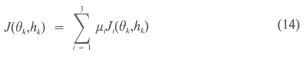
where J1 = | w0|, J2 = -ωmn, J3 = -N, and μi > 0 are the constants which reflect the relative importance of minimizing Consequently, the numerical problem to be solved is the following:
It is known that a minimizing solution of J(0k,hk) with μi > 0 i = 1,2,3 is a Pareto optimal solution [18, 19, 20]. Moreover, a unique minimizing solution with μi, > 0, i = 1,2,3, μi + μ2 + μ3 ≠ 0, is also known to be Pareto optimal [21]. This result enables us to determine the end points of optimal trade-off curves from a computation of single purpose designs provided these are unique. It should be noted that a solution obtained by minimizing (14) is not necessarily the unique POS. The numerical results given in the sequel represent the solutions calculated using the performance index (14). Different POS's can be computed from the minimization of J(0k,hk) with different values of μi. For further details on Pareto optimality we refer to [22, 23]. Different methods of computing POS are discussed in [23].
At the beginning of a design process, it is impossible for the designer to specify the relative importance of each objective function since the best possible performances of the plate are not known at this stage. In this sense, a multiobjective design is an interactive process. The designer decides on the values of relative weights after studying the response of the system under various loads.
A useful tool in assessing the performance of a design with multiple objectives is the optimal trade-off surface in the attainable criteria set, that subset of the criteria space (i.e., Ji-space) which is the image of the decision set under the mapping J = (J1,J2,J3). It represents the points of optimum plate performance.
In the case of a design with two objectives, we have "an optimal tradeoff curve" in the /,/2-plane, the end points of which give the response of a single purpose design. Intermediate points represent the trade-off between the objectives with respect to their best possible values. In the end, it is the designer who must choose any one of these optimum response points, corresponding to a certain set of values of the weights, by taking various design requirements into account.
In the next section, we give the optimal trade-off curves for a number of examples.
Optimal Tradeoff Curves
We obtain the Pareto optimal designs of the laminated plates by minimizing the objective function (14) subject to (8-10) with different weights μi. The design procedure is illustrated on the simpler cases of problems with only two objective functions. This facilitates the graphical presentation and the discussion of the results. The numerical results are obtained using a quasi-Newton nonlinear function minimization routine, formulated in [14]. In the first example, the laminate is optimized with respect to dynamic deflection and natural frequencies, i.e. in equation (14) μ3 = 0. In the second example, the optimization is carried out with respect to the fundamental frequency and the buckling load, i.e. in equation (14) μ, = 0. Optimal trade-off curves of both cases are determined for various problem parameters. Numerical results are given for a carbon fiber reinforced epoxy plastic for which E1/E2 = 40.0, G12/E2 = 0.5, v12 = 0.25. We note that the computer program to evaluate w0, ωmn, and N has been tested by comparing the results with those of [17].
For the plate undergoing forced and free vibrations, the objective function (14) becomes

We choose the forcing function as f{x,y) - sin nx sin ny in which case w0 is given by (A8) with m = η = 1. We first obtain the design of plates with a single objective by setting β = 1 and β = 0 in (16). The results for single purpose designs are given in Table 1 for four- and six-layered plates with aspect ratios 1 or 2. In these problems the design parameters are 0k and the layers are of equal thickness with hk = 1 /K. When the forcing frequency λ is less than the first resonance frequency, which is equal to the fundamental frequency, and f{x,y) = sin nx sin ny, the min-max deflection design is given by layers oriented alternately at angles 45 deg and - 45 deg. When λ is greater than the resonance frequency, this result does not hold true. Table 1 shows computations with λ less than and greater than the resonance frequency of the plate. We retained the minus sign of the maximum deflections to emphasize the cases where the response of the plate is out of phase with the external force. We assess the efficiencies of the optimal designs by comparing them with the corresponding standard plate which we define to be composed of layers of equal thickness with the fibers oriented alternately at 45 and -45 deg. In the tables, the subscripts op and s refer to the optimal and standard plates, respectively. Thus the efficiencies with respect to w0, ωmn and Ν are defined as the ratios wop/ws, ωορ/ωχ and Nop/Ns, respectively. We note that the values of ω, for Κ = 4 and 6 with r = 1, m = η = 1 coincide with the corresponding values in Fig. 5.22 of [17]. Moreover, these values give the maximum ω,, for those specific single purpose designs. Optimality and uniqueness of those designs can be as certained from Fig. 5.22 of [17]. The results for optimal 0k's are given for only one half of the laminate with the understanding that the remaining half is oriented antisymmetrically. We observe that single purpose designs may be quite efficient with respect to one of the performance criteria, while they may be rather inefficient with respect to the other.
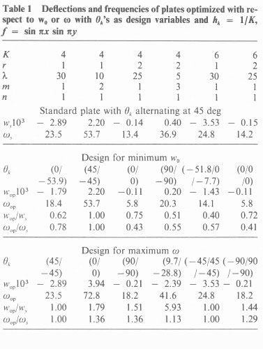
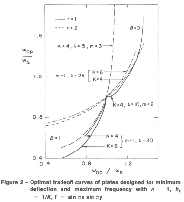
Optimal trade-off curves of the cases given in Table 1 are shown in Fig. 2. Here the end points of each curve indicate the values of wop/ωs and ωορ/ωs for single purpose plates. For intermediate values 0 < β < 1.
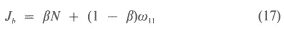
In the second example, the plate may be undergoing free vibrations or subjected to in-plane loads during its service life. The design objectives are taken as the fundamental natural frequency and the buckling load and the performance index to be maximized is
where 0 < β < 1. The results for single purpose designs are given in Table 2 for four-layered plates with r = 2 or 3. The design parameters are either 0,,02 with layer thicknesses hk = 0.25 or 0, = -02 and A, (h2 = 0.5 - hi). The fiber orientation design for maximum Ν was given in [12] for the case r = 3, Κ = 4, hk. = 0.25. The design (45/ - 45) and Nop = 56.1 in [12] are the same as our results given in Table 2 for this case.
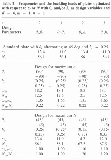
We note that for the optimal thickness values h1 = 0.15, h2 = 0.35, and 01 = -θ2 = π/4, the coupling stiffness coefficients B16 = B26 = 0 and the laminate behaves like an orthotropic plate. The critical ratio hjh2 = 0.41 when 0, = - θ2 was derived analytically in [24] as a condition for B16 and B26 to vanish. We observe that the designs for maximum ω11 can carry relatively small buckling loads as compared to standard plates. We note that for the design angles 01 = - 02 = 90 deg, the ratio h1/h2 becomes immaterial in the computation of the stif-nesses Aij,Βij,Dij and consequently does not effect the optimal design. In Table 2, we set h1 = h2 = 0.25 for the case 01 = -02 = 90 deg.
The optimal trade-off curves of the cases given in Table 2 are shown in Fig. 3. We observe that the efficiency of a design can be improved considerably by including the layer thicknesses among the design variables.
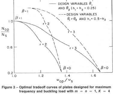
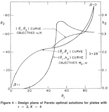
Figure 4 shows the curves of 01 plotted against 02 and h2 for various cases. The end points of these curves again give the designs for single purpose plates. Any intermediate point corresponds to a Pareto optimal design with 0 < β < 1 in the performance indices (16) or (17). We observe that the design parameters continuously change as β moves along the interval [0, 1].
Conclusions
Multiobjective design of an antisymmetrically laminated angle-ply laminate was given with respect to
(a) maximum dynamic deflection and fundamental and higher order natural frequencies, and
(b) fundamental frequency and the buckling load.
The design variables were taken as fiber orientation and/or thickness of each layer and were determined by the method of nonlinear programming. The numerical results were presented in the form of optimal trade-off curves. The final decision as to what point on these curves will give the most suitable design must be made by the designer and essentially represents a compromise solution with regard to conflicting objectives.
Optimal designs are compared with a standard plate defined as the one, the layers of which are equal thickness and have fibers oriented at alternating angles of 45 deg. It was observed that the performance of a multipurpose plate in general, is better with respect to one of the objectives but worse with repect to the other in comparison with a standard plate. Optimal trade-off curves for a given set of objectives show the best possible responses of a plate to different loading conditions and thereby allow the designer to explore various trade-offs involved in a certain design.
References
1. Schmit, L. A., Jr., and Farshi, B., "Optimum Laminate Design for Strength and Stiffness," International Journalfor Numerical Methods in Engineering, Vol. ~\ 1973, pp. 519-536. [ Links ]
2. Hayashi, T., "Optimum Design of Cross and Angle-Plied Laminated Composite Plates under Compression," Fukugo Zairyo Kenkyu (Composite Mails, and Structures,, Japan), Vol. 3, No. 2, 1974, pp. 18-20. [ Links ]
3. Bert, C. W., and Chen, T. L. C, "Optimal Design of Composite-Material Plates to Resist Buckling under Biaxial Compression," Trans. Japan Soc.for Composite Materials, Vol. 2, No. 1, July 1976, pp. 7-10. [ Links ]
4. Bert, C. W., "Optimal Design of Composite-Material Panels for Business Aircraft," Business Aircraft Meeting of Society of Automotive Engineers, Wichita, Kansas, March 29-April 1, 1977.
5. Schmit, L. A., Jr., and Farshi, B., "Optimum Design of Laminated Fibre Composite Plates," international Journal for Numerical Methods in Engineering, Vol. 11, 1977, pp. 623-640 [ Links ]
6. Mckeown, J. J., "Optimal Composite Structures by Deflection-Variable Programming," Computer Methods in Applied Mechanics and Engineering, Vol. 12, No. 2, 1977, pp. 155-179. [ Links ]
7. Bert, C. W., "Optimal Design of a Composite-Material Plate to Maximize its Fundamental Frequency," Journal of Sound and Vibration, Vol. 50, No. 2, 1977, pp. 229-237. [ Links ]
8. McKeown, J. J., "A Fixed Upper Bound on the Number of Layers in Optimal Composite Sheets," international Journal of Solids and Structures, Vol. 14, 1978, pp. 113-119. [ Links ]
9. Bert, C. W., "Design of Clamped Composite-Plates to Maximize Fundamental Frequency," ASME Journal of Mechanical Design, Vol. 100, Apr. 1978, pp. 274-278. [ Links ]
10. Lukoshevichyus, R. S., "Minimizing the Mass of Reinforced Rectangular Plates Compressed in Two Directions in a Manner Conducive Toward Stability," Polymer Mechanics, Vol. 12, No. 6, 1976, pp. 929-933. [ Links ]
11. Rao, S. S., and Singh, K., "Optimum Design of Laminates with Natural Frequency Constraints," Journal of Sound and Vibration, Vol. 67, 1979, pp. 101112. [ Links ]
12. Chen, T. L. C, and Bert, C. W., "Design of Composite-Material Plates for Maximum Uniaxial Compressive Buckling," Proc. Oklahoma Academy of Science, Vol. 56, 1976, pp. 104-107. [ Links ]
13. Hirano, Y., "Optimum Design of Laminated Plates under Axial Compression," AIAA Journal, Vol. 17, No. 9, Sept. 1979, pp. 1017-1019. [ Links ]
14. Gill, P. E., and Murray, W., "Minimization Subject to Bounds on the Variables," National Physical Laboratory Report Ν AC 72, 1976.
15. Gill, P. E. and Murray, W., "Quasi-Newton Methods for Linearly Constrained Optimization," Numerical Methods for Constrained Optimization, Academic Press, London, 1974, pp. 67-90.
16. Whitney, J. M., and Leissa, A. W., "Analysis of Heterogeneous Anisotropic Plates," ASME Journal of Applied Mechanics, Vol. 91, 1969, pp. 261-266. [ Links ]
17. Jones, R. M., Mechanics of Composite Materials, McGraw-Hill, New York, 1975.
18. Zadeh, L. A., "Optimality and Non-scalar Valued Performance Criteria," IEEE Trans. Automatic Control, Vol. 18, 1963, pp. 59-60. [ Links ]
19. Dacunha, N. O., and Polak, E., "Constrained Minimization under Vector-valued Criteria in Linear Topological Spaces," Mathematical Theory of Control, Academic Press, New York, 1967.
20. Olmstead, W. E., and Schmitendorf, W. E., "Optimal Blowing," SIAM Journal on Applied Mathematics, Vol. 35, Nov. 1978, pp. 548-563. [ Links ]
21. Leitmann, G., and Schmitendorf, W. E., "Some Sufficiency Conditions for Pareto Optimal Control," ASME Journal of Dynamic Systems, Measurements, and Control, Vol. 95, 1973, pp. 356-361. [ Links ]
22. Stadler, W., "Preference Optimality and Applications of Pareto Optimality in Multicriteria Decision Making,,' CIS M Courses and Lectures No. 211, Leitmann, G., and Marzollo, A., eds., Springer-Verlag, Vienna, 1976.
23. Brayton, R. K., Hachtel, G. D., and Sangiovanni-Vincentelli, A. L., "A Survey of Optimization Techniques for Integrated-Circuit Design," Proceedings of the IEEE, Vol. 69, Oct. 1981, pp. 1334-1362. [ Links ]
24. Sharma, S., Iyengar, N. G. R., and Murthy, P. N., "Some Comments on the Coupling Effects of Angle-Ply Laminates," Journal of Structural Mechanics, Vol. 7, 1979, pp. 473-482. [ Links ]
* National Research Institute for Mathematical Sciences Reprinted from the Transactions of the ASME, June 1983.
Appendix
Plane Stress Reduced Stiffness Components of &th Layer
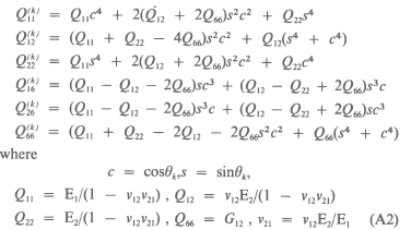
where E1, E2 are Young's moduli in the longitudinal and transverse directions, respectively; v12 is the ratio of transverse-to-longitudinal strain under longitudinal stress; and Gl2 is the shear modulus in the 12-plane.
Nondimensional Form of the Differential Equations and the Boundary Conditions
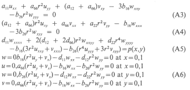
where p(x,y) = λ2r4w + f(x,y) for the forced vibrations, p(x,y) = ω2r4 w for the free vibrations, and p{x,y) = -Nr2wxx in the buckling problems and
where sk = Sk/H, Sk is the distance to the centroid of the k-th layer.
Expressions for the Dynamic Deflection, Natural Frequencies and the Buckling Load