


Servicios Personalizados
Articulo
 Inglés (pdf)
 Articulo en XML
 Referencias del artículo
Indicadores

Links relacionados
-
 Citado por Google
 -
 Similares en Google
Compartir

 Permalink
Journal of the Southern African Institute of Mining and Metallurgy
versión On-line ISSN 2411-9717
versión impresa ISSN 2225-6253
J. S. Afr. Inst. Min. Metall. vol.124 no.1 Johannesburg ene. 2024
http://dx.doi.org/10.17159/2411-9717/1030/2024
PROFESSIONAL TECHNICAL AND SCIENTIFIC PAPERS
A practical approach to determine the role of rockbolts in stoping gullies
J.P. GouveaI; T.R. StaceyII
INortham Platinum Holdings, South Africa. ORCID: J.P. Gouvea. http://orcid.org/0000-0003-2970-6691
IIUniversity of the Witwatersrand, South Africa
SYNOPSIS
A research project was carried out on a gold mine in the Vaal River region of South Africa (Witwatersrand Basin) to evaluate the effect of two particular aspects of rockbolt installation - the angle of inclination of the bolt relative to the orientation of the rock surface, and the protruding length of the bolt - on the mine's gully support system. A keyblock analysis approach indicated that these factors do not have an adverse impact on the stability of the strike gullies. This was confirmed by extensive empirical data collected from the case study mine. While safety is the primary concern, cost saving opportunities can be realized through reconsidering historically inherited support standards that are perceived to be correct and appropriate. The research described in this paper sets forth a practical approach, that is easy to implement and repeatable, to evaluate the role of rockbolts in stoping gullies.
Keywords: stope gully, rockbolts, support design, protrusion, flat angle, key block.
Introduction
South Africa has been one of the world's primary gold producers since the late 19th century, and mines have had to develop to greater depths than ever before. Excavations of different sizes and shapes created in underground mining require the installation of support in order to remain open and stable for their required lifespan. Rockbolts represent one of the components of rock support and are widely applied throughout the mining and civil engineering sectors. Historically, rockbolt support in South African mines was required to be installed at an angle between 70° to 90° to the excavation periphery or strata. In addition, mine standards have generally specified that rockbolts protruding by more than 30 cm should be replaced. These historical standards were quite logical, since they originated from early end-anchored rockbolts that had only 30 cm of thread for tensioning or re-tensioning. If such a bolt protruded by more than 30 cm, it was impossible to re-tension it and thus replacement was required. Furthermore, if the bolts were installed at an angle of less than 70° to the rock surface, the thickness of the supported rock arch would be less than the designed thickness, which could allow rockfalls to occur.
Since then, more sophisticated rockbolt designs and gully support systems have been developed, However, many mining operations have continued to 'accept' and religiously enforce historically inherited standards related to rockbolting. The reconsideration of these standards is the subject of the research described in this paper.
Industry rockfall accident statistics
Since this paper involves the consideration of current support procedures, it is appropriate to review the industry's performance in combatting rockfalls and rockbursts.
Falls of ground have accounted for most of the fatalities and injuries in the South African mining industry. On average, a third of the fatalities reported each year have been due to uncontrolled falls of ground. Most of these fatalities were recorded in the gold and platinum mining sectors, which typically employ labour-intensive, conventional methods in hard-rock, narrow tabular excavations. These statistics are not necessarily directly comparable with other commodity sectors since physical and geotechnical conditions differ significantly both locally and internationally.
The health and safety of mineworkers remain the highest priority for all stakeholders across the mining industry.
Rockbolt support
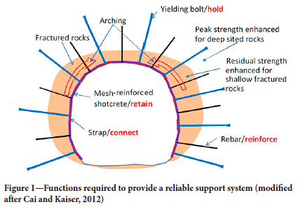
The fundamental support functions of rockbolts have remained consistent throughout the years (refer to Figure 1):
► Reinforce the rock mass
► Contain fractured rock
► Retain the deformation compatible surface support
► Facilitate connection between rockbolts and surface support with non-failing connection elements (nuts, plates, strapping, rope lacing etc.).
Surface and reinforcement support elements are typically combined to interact with each other to create an integrated support system. Each support element interacts differently with the rock mass and therefore performs a different function within a system. Li et al., (2016) reported that the overall performance of a support system is lower than the sum of individual support elements. This emphasizes that each support element reacts differently to the behaviour of a rock mass and does not provide the same support characteristics at different stages throughout this process. Consequently, the role of rockbolts within a support system must be carefully considered in relation to the conditions in which the bolts are installed.
Understanding the fundamentals of a rockbolt support unit, its interaction with the rock mass, and its role relative to other support units in a support system, is imperative in determining the effects that installation angle and length of protrusion may have on support performance. Rockbolts subjected to different loading conditions do not behave similarly, making the selection of a bolt type important.
A challenge experienced in the industry is that the choice of rockbolts is often dictated not by their supporting capability, but by their ability not to interfere with other mining activities, and by their compatibility with other mining engineering operations.
Low stress conditions
Underground excavations may expose joints, bedding planes, other geological discontinuities, and blasting-induced fractures, that play a significant role in the stability of excavations (Li, 2017). Displacements can take place along these discontinuities, resulting in instability if support is inadequate. The influence of discontinuities is exacerbated at shallow mining depths where clamping forces are typically limited.
The basic requirement of a rockbolt installed in low stress conditions is that its capacity should exceed the load applied on it by the surrounding rock mass (Li, 2017). The loads are typically determined by the height of potential rock mass instability ('deadweight' or tensile dome). Rockbolts develop tensile and shear support resistance as the rock mass surrounding an excavation deforms. In low stress environments, closure rates in excavations are generally slow, and yielding support capabilities are not required.
However, the rockbolts are usually pre-stressed to offer a high initial load and provide active support to the rock mass.
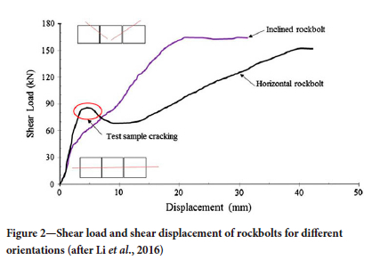
Combinations of loading imposed on a rockbolt (not necessarily only under the influence of gravity) have a significant impact on the overall performance of the bolt. Rockbolts usually experience a combination of tensile and shear loading. Double shear laboratory tests conducted by Ayres and Gardner (2014) to quantify the effect of different installation angles on the performance of rockbolts indicated that failure loads were higher as the shear component decreased relative to the tensile component. Similarly, Li et al., (2016) reported that the variation in rockbolt installation angle relative to discontinuities affects both the peak support load and the rigidity of the support (Figure 2). They found that a higher initial stiffness is achieved by installing a rockbolt perpendicular to a weakness plane rather than at an acute angle. However, in contrast, a higher peak shear load is achieved by installing rockbolts at an acute angle to discontinuity planes owing to the tensile component.
High stress conditions
Rock failure is unavoidable in high stress conditions (Bhatt, Meena, and Badhwar, 2018). Therefore, dynamically capable ground support, such as yielding rockbolts, should be installed to maximize the absorption of strain energy released during a seismic event, and restrict the displacement of rock around excavations.
Owing to the depth and absence of weathering, discontinuity planes tend to be less frequent at increased depths, and spacings between weakness planes tend to be greater. Consequently, a higher quality rock mass is often exposed in deeper mining operations owing to the reduced number of open, unclamped discontinuity planes. However, large-scale deformations associated with elevated stress levels can pose a significant risk to the stability of excavations. Rock squeezing (in soft rock) and rockbursting (in hard rock) are two typical loading mechanisms found in deeper mining operations in high stress conditions.
Large deformations (squeezing) can be anticipated in weak and soft rock subjected to high stress conditions. Rock squeezing is influenced by geological structure as well as rock type. The surrounding rock mass is typically weak, frequently jointed, and fractured where squeezing takes place. A critical strain is defined on the periphery of an excavation at which squeezing takes place (Bhatt, Meena, and Badhwar, 2018). The information is utilized to locate tunnels in favourable conditions in order to avoid squeezing (if possible) and/or to inform a designer where to implement energy-absorbing support. Typically, rockbolts in a high stress environment prone to squeezing are utilized to limit rock mass deformations (high support resistance), while also having the ability to be more ductile to cater for large deformations. The support can entail one rockbolt type satisfying both functions, or different types within a support system being utilized to achieve the goal.
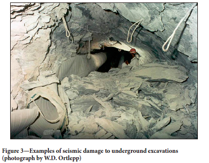
In deep-level, hard rock environments, seismic events can pose considerable risks to mining operations (Figure 3). The selection of suitable rockbolt support units in burst-prone conditions is reliant on the appropriate identification of likely rockburst damage mechanisms (Ortlepp and Stacey, 1994). Each mechanism influences a support system differently and as such, should be considered separately (combination loading is also possible). Owing to the difficulty of predicting the location and magnitude of seismic events and the direction of loading, the demand on support is unknown. Furthermore, the capacities of support systems are also unknown, resulting in a situation of design indeterminacy. A potential solution is to install a conservative amount of support that is then likely to prevent, or at least limit, rockburst damage (Stacey, 2011).
Evaluating the influence of angle of installation and protrusion on gully rockbolt performance
To evaluate the influence of protruding rockbolts and bolts installed at an acute angle, it was decided to examine a case study in detail.
The evaluation mainly considered stope gullies situated on the reef horizon, where rockbolts were being systematically installed. The following assessments were conducted:
► An analytical approach to support design based on the 95% cumulative fallout height of recorded falls of ground
► A probabilistic keyblock analysis based on geotechnical data mapped underground
► An analysis of the mine's database on fall-of-ground accidents and incidents
► An observational approach based on actual underground observations.
Geological and seismological setting and background
The case study mine is situated in the Klerksdorp Goldfield of the Witwatersrand Basin. The mine accesses the conglomerate reefs, the most important of which is the Vaal Reef (VR), through a twin shaft system with a maximum depth of 2 334 m below surface (intermediate to deep). Shaft sinking was initiated in 1977 and completed by 1981, with production commencing in 1984. The main working levels are situated between 1 300 m and 2 064 m below surface, resulting in typical virgin stress levels ranging between 35 MPa and 55 MPa.
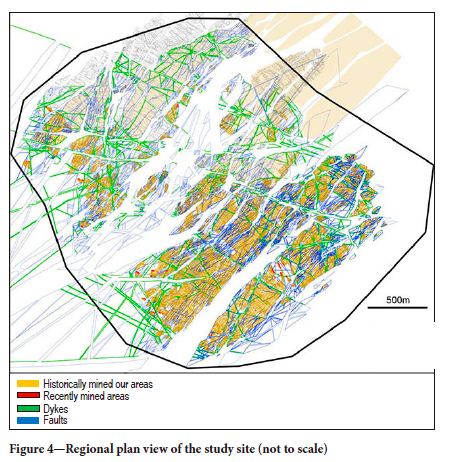
The narrow tabular orebody, 1 m thick on average, dips at some 21° towards the south. Owing to a combination of faulting and intrusions in the area, a conventional scattered mining method (Hamrin, 1980) is used. The operation is a marginal mine (low grade) with a large footprint as shown in Figure 4.
The main sources of seismic activity at the mine are:
► Geological features (faults and dykes), particularly at their intersections
► Remnants and/or isolated pillars, particularly when intersected or bounded by seismically active geological features.
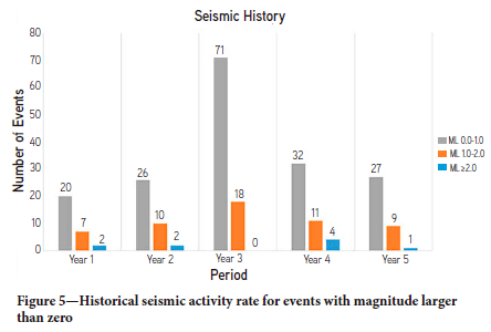
True facebursts are rare and do not demonstrate a trend. In most cases, minimal or no damage has occurred to the workings following events of magnitude less than 2.0. Events larger than this, and any unusual seismic occurrences, are investigated individually to determine their impact in order to verify the site response. Figure 5 illustrates a 5-year history of seismic events of various magnitudes that took place within the operation's boundaries. Although the mine is seismically active, dynamic loading of rockbolts was not a major consideration in the case study.
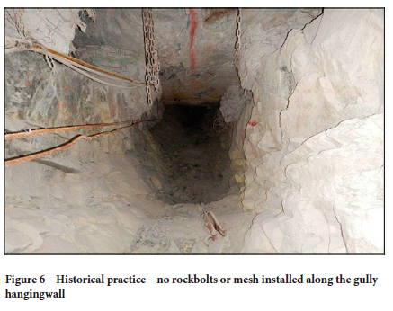
Historically, timber packs were installed on both sides of stope gullies (Figure 6). These gullies are not used only for travelling purposes, but also to move broken rock from the panel face on a cyclical basis. In 2002, stope gullies were classified as the second highest risk excavations in the South African hard rock mining industry (Naidoo, Leach, and Spencer, 2002).
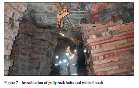
Soon after the SIMRAC report was published (Naidoo, Leach, and Spencer, 2002), the study site adopted the support recommendations in the report, which included the introduction of welded mesh and rockbolts along the gully hanging wall (Figure 7).
The introduction of welded mesh and rockbolt support at in-stope gullies was well intended, but it unfortunately had unexpected ramifications. Since the inherited principles pertaining to the installation angle and protrusion of rockbolts appeared in the mine support standards, these aspects became auditable by the Department of Mineral Resources. Frequent non-compliance with the standards resulted in mine-wide stoppages. To avoid further stoppages by mining regulators, elaborate mesh and rockbolt rehabilitation strategies were implemented, at unsustainable cost (Figure 8).
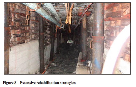
The rehabilitation costs, in the range of R7 000 to R12 000 per linear metre, were significant considering the strike length of the stope gullies. In spite of these efforts, the study site still experienced stoppages.
It is reiterated that this paper does not aim at justifying substandard practises. On the contrary, it challenges the origin and validity of historical mining standards with regard to stoping gully rockbolts. More importantly, by means of sound geotechnical assessments, the role and effectiveness of gully rockbolting is quantified and classified for the case study site.
Evaluation of current support design
The 95% cumulative fallout height of observed falls of ground on the mine is used to determine the support requirements (13.6 kN/m2 required as dictated by the mine Code of Practise). Pack support is a major factor when assessing the role that rockbolts play in gully stability. Packs are installed on gully shoulders, with rockbolts between them along the hangingwall of the gully. Support resistance calculations in the gully area, based only on the loads generated by the pack support, for various distances from the face, are shown in Table I (tributary area method). The mine standard requires that packs are installed a maximum of 3.2 m from the panel face and systematically on both sides of the gully shoulders towards the back area (note the change in pack support area).
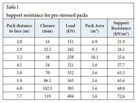
As stope closure increases, the support resistance provided by gully packs progressively increases. Based on the mine's 95% cumulative fallout height of observed falls of ground and the support resistance provided by the pre-stressed packs, a stable factor of safety was achieved. For example, at a distance of 5 m from the panel face, the support resistance generated by pack support on the gully shoulders is 63.3 kN/m2. This resulted in a factor of safety well above 1.6, which well satisfied the static loading requirements of the mine.
Geotechnical data and probabilistic keyblock analysis
A database detailing the presence, orientation, and condition of rock mass discontinuities was compiled to gain an understanding of the mining conditions and assess likely failure mechanisms. Geotechnical mapping of the hangingwall was conducted at 11 workplaces across the enire study site (scan line mapping), totalling 312 m in length. To characterize the rock mass and avoid bias, the exposed hangingwall was mapped in both dip and strike directions, as not all joints will be visible in only one excavation orientation. Core recovered from geological boreholes was also used to create a complete three-dimensional model of the surrounding rock mass. Mapping included measurement of the orientation, frequency, persistence, and contact surface condition of joints present in the host rock.
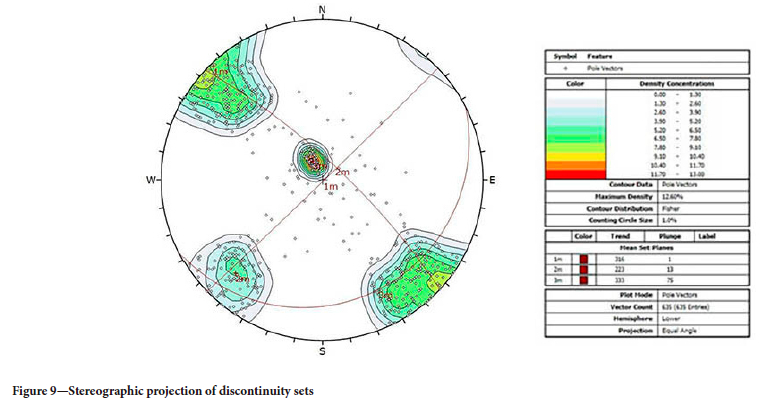
Stereonets were used to assess the orientations of discontinuity planes recorded during mapping (635 readings). This sample size was considered to be adequate to identify all discontinuity sets and to quantify the distributions of their orientations. The joint parameters were assessed on a continuous basis for quality control purposes. The quality control procedures included visual inspection of data, identification of anomalous data trends, comparison with underground observations, and assessment of the validity of the data.
Figure 9 depicts the selection of discontinuities for the quantification of joint sets.
Three joint sets, and a random joint set, can be observed from the stereonet projection. Joint set 1 was considered as two separate joint sets (J1 and J1i) due to the variability in dip direction. Most of the identified joint sets are steep dipping (J1, J1i, and J2), with one flat dipping joint set (J3 - bedding planes). Joint sets J1 and J2 are orthogonal and when interacting with the flat dipping joint set J3 can create key blocks. For each discontinuity mapped, the following parameters were recorded:
► Ends of joints (one, two, or no ends visible)
► Joint length or persistence
► Joint spacing.
When evaluating joint trace lengths underground, it is often not possible to determine the actual joint length if joints terminate beyond the excavation boundaries. While gathering the data, it was therefore important to note whether both ends of a joint were visible (E2), only one end was visible (E1), or both ends terminated into the excavation boundaries (E0). The E0 type joints may participate in the formation of numerous key blocks due to the long trace lengths. Note that there is uncertainty in respect of the persistence of type E1 joints due to only one end of the trace being visible.
From a statistical analysis of joint persistence and applying engineering judgement, the descriptive statistical parameters for each joint set, namely maximum, minimum, and mean joint persistence, were calculated. J1appears to be the most prominent joint set; however, this conclusion may be slightly biased due to the orientation of the bedding planes relative to the scan lines. Set J3 is characterized by the longest trace lengths. Set J2 is marginally less persistent and less prominent than the others. Joint spacings were measured for each scan line, and a spacing adjustment applied to correct for the bias introduced by the scan line orientation. Based on the joint characteristics and orientations, only one ground control district (GCD) could be identified.
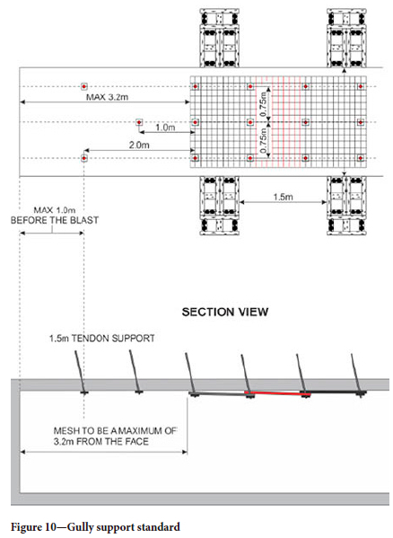
JBlock, a keyblock stability model (Esterhuizen, 2003), was utilized in the comparative assessment, rather than to provide absolute answers. JBlock is a probabilistic approach to keyblock analysis, providing qualitative or comparative analyses relating to falls of ground and support layouts (Esterhuizen and Streuders, 1998). JBlock has been shown to be useful in estimating the relative hazard of rockfalls in tabular mining layouts in South Africa (Joughin et al., 2012a; 2012b). The model geometry for the JBlock analyses was derived from the study site's mine standards booklet as depicted in Figure 10.
The stope can be divided into zones of interest, since personnel exposure and the remediation strategies will differ in each of these zones. For the purposes of this study, the zones of interest were the gullies where rockbolts are being installed.
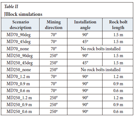
A total of 12 simulations had to be run to cater for the number of permutations created by the variability in influencing factors (rockbolt installation angle and rockbolt length) and different mining directions. Two different mining directions were evaluated (East - azimuth 70° and West - azimuth 250°) since, based on observations in other projects, the formation of key blocks was expected to be dependent on mining direction. The effects of rockbolt protrusion length (0.6-1.5 m) and installation angle (-90°), as well as the effect of not installing rockbolts ('no rock bolts installed') in gullies, were assessed.
The current mine support standard was compared with the scenarios in Table II.
In addition to the block filtering routine that is implemented while creating synthetic blocks, subsequent block filtering is applied prior to evaluating the influence of artificial support. The purpose of this stage of filtering is to simulate the effect of natural support mechanisms such as clamping stress in the hangingwall, which acts on key blocks that exceed a certain threshold aspect ratio and mid-height.
Figures 11 and 12 compare the current support standard (MD70_90deg and MD250_90deg) and the effectiveness of the support system in the cases of protruding rockbolts and bolts installed at an acute angle. In the graphs, the green bar (far left) represents the current support standard and the blue bars (the second and subsequent bars) represent the performance of the support system when protruding rockbolts and bolts installed at an acute angle are prevalent. For comparison purposes, the numbers of falls of ground have been normalized relative to the exposed face area in the model. A value of 10 000 m2 of exposed gully face area was used for normalizing.
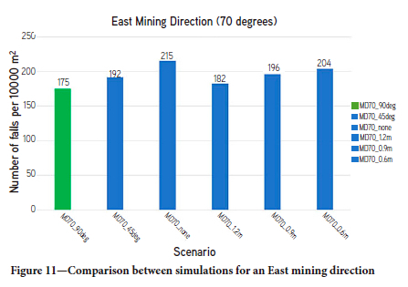
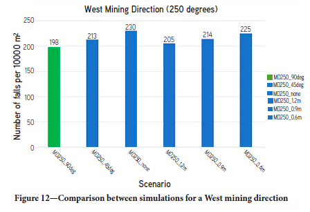
A very low probability exists for failures in gullies. On average, 187 rockfalls were simulated per 10 000 m2 of exposed gully face area mined for the current mine support standards. The numbers of rockfalls increase to 223 per 10 000 m2 mined, on average, when no rockbolts are installed. The failures indicated by the keyblock analysis were at the gully face, prior to installation of the packs along the gully shoulders. Such failures were not observed underground, nor recorded in the mine's fall of ground database: they may take place during blasting, and/or are controllably removed during barring activities. The conclusion from the keyblock modelling is that protruding rockbolts and bolts installed at an acute angle in gullies at the study site did not contribute significantly to the rockfall hazard in the stoping gullies.
Mine's fall of ground accidents and incidents database
All the mine's accident and incident reports over a five-year period were assessed. Falls of ground were responsible for 14% of accidents on the mine. This percentage was deemed significant considering the severity of such accidents. Figure 13 indicates the general locations of falls of ground in the period that was assessed.
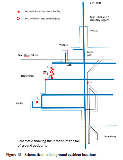
The majority of fall of ground accidents occurred in the stoping environment, as expected. Fall of ground number 2, as depicted in Figure 13, is situated in a gully where rockbolts were being installed. However, the fall was not a result of protruding rockbolts or rock installed at an acute angle.
Underground observations of rockfalls
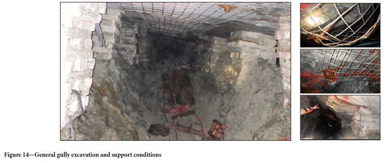
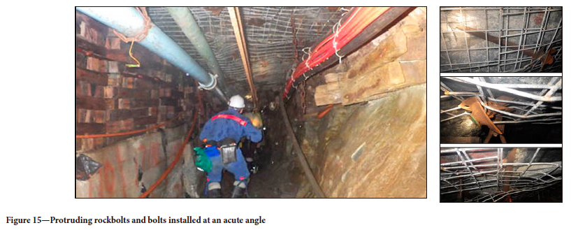
Underground inspections were carried out at 24 workplace gullies across the mine. A total distance of 1240 linear metres was inspected to identify protruding rockbolts and bolts installed at an acute angle. Most of the rockbolts were installed at an angle less than 70° to the hangingwall (68%), and many were protruding by more than 30 cm (11%). Rockbolts were installed at an average angle of 45o to the hangingwall. However, in the 1240 m inspected in the 24 workplaces, no instabilities were observed relating to protruding rockbolts, nor to bolts installed at a flat angle (refer to Figures 14 and 15).
Some of the underlying reasons for the acute installation angles and protruding gully rockbolts were practical and/or situational constraints. Congestion with broken rock restricts the height of the gullies and results in operators adjusting the angle of installation to suit the required tools and equipment (hand-held drilling). Installation angles were normally flatter in the direction of advance, which under these circumstances can be considered favourable. Protruding rockbolts were not mainly attributed to the fallout of small rocks from the hangingwall of the stope gully, but to undulating or uneven hangingwall conditions. The loading interaction between the welded mesh and rockbolt faceplate prevents the faceplate from being pushed flush against the rock wall.
Discussion
The choice of support systems in South African hard-rock tabular mines has historically been based on cost considerations, empirical knowledge, engineering judgement, and past practices. In a changing mining industry of emerging technologies, past practices may become obsolete, and the lack of rigorous reviews of support designs may result in support systems that are not optimized, nor effective. In this study, past practices (standards) relating to rock bolt support units were investigated:
► Rockbolts should be installed between 70° to 90° to the excavation periphery or strata
► Rockbolts protruding by more than 30 cm should be replaced. These standards were evaluated regarding the support
installed in stope gullies in a medium- to deep-level gold mine. Four approaches were followed. Firstly, based on the mine's 95% cumulative fallout height of observed falls of ground, and on the support resistance provided by the pre-stressed packs, a stable factor of safety was achieved.
Secondly, a probabilistic keyblock analysis method, JBlock, was used to conduct a comparative analysis. To provide the required input data, a geotechnical database was created through underground geotechnical scanline mapping. In the JBlock analyses, the mine's current support standard was compared with scenarios in which rockbolts were installed at an acute angle, bolts were protruding, and where no rockbolts were installed in gullies. The results indicated that:
► A very low probability exists for failures in gullies.
► Rockbolts installed at an acute angle, and protruding rockbolts, do not have a significant impact on the stability of gullies
► The main purpose of gully hangingwall rockbolts, on the specific operation is not to increase the resistance of the support system, but in conjunction with welded mesh, to maintain the stability of small key blocks. This is the stable beam building function of rockbolt support.
Thirdly, all the mine's accident and incident reports over a five-year period were reviewed. The majority of events occurred in the stoping environment, and none of the instabilities was directly or indirectly related to protruding rockbolts or rockbolts installed at an acute angle.
Lastly, underground inspections were carried out at 24 workplaces at depths ranging between 1200 m and 2100 m below surface, in different geotechnical areas across the mine. A total distance of 1240 linear metres was inspected for protruding rockbolts and bolts installed at an acute angle. Most of the rockbolts observed underground were installed at an angle less than 70° to the hangingwall (68%), and a smaller number of bolts protruded more than 30 cm (11%). Rockbolts were installed at an average angle of about 45° to the hangingwall. However, despite the deviations from the prescribed 'standard', no instabilities were observed.
In summary, the results of the investigation confirmed that the prevalence of protruding rockbolts and bolts installed at an acute angle does not have a detrimental impact on the stability of stoping gullies. This was mainly attributed to the reinforcing nature or role of the rockbolts being installed. This also supported the notion that past practices or standards may be obsolete and can be optimized to benefit mining operations without affecting safety. Alternatively, it can be deduced that surface support provides sufficient areal coverage to cater for the majority of potential instabilities in gullies. As a result, rockbolts merely fixing mesh to the hangingwall of gullies can be deemed appropriate and would be more cost-effective by providing same support effect with fewer support drilling metres.
Conclusions
The results of the investigation showed that the deviation from historical standards did not result in a significant increase in rockfalls. This finding justified the revision of historical mine standards, with consequent cost-saving opportunities, and without compromising safety. It is noted that, although the study was conducted in stope gullies, it can be expected that the approach followed will be equally applicable to tunnels and other mining excavations. However, it is recommended that this is confirmed by additional research and case studies.
It is important to note that, despite the indications from the research, the authors do not advocate omitting rockbolts and welded mesh from stope gullies. The advantages of such a support system are well documented. The role that rockbolts serve in stoping gullies should be duly considered and historical (or inherited) support standards adjusted to maintain their effectiveness.
References
Ayres, N.L. and Gardner, L.J. 2014. Testing tendon support units under a combination loading scenario. Journal of the Southern African Institute of Mining and Metallurgy, vol. 114, no, 10. pp. 829-834. [ Links ]
Bhatt, H., Meena, M., and Badhwar, M. 2018. Design principle of rockbolting. Verdant College of Engineering and Technology. Rajasthan, India. pp. 363-368. [ Links ]
Cai, M. and Kaiser, P. 2012. Principles of rock support in burst-prone ground. Tunnelling and Underground Space Technology, vol. 36. pp. 33-46. [ Links ]
Esterhuizen, G.S. 2003. JBlock User Manual. Department of Mining Engineering, University of Pretoria. [ Links ]
Esterhuizen, G.S. and Streuders, S.B. 1998. Rockfall hazard evaluation using probabilistic key block analysis. Journal of the South African Institute of Mining and Metallurgy, vol. 98. pp. 59-64. [ Links ]
Hamrin, H. 1980. Guide to underground mining methods and applications. Atlas Copco, Stockholm, Sweden. [ Links ]
Joughin, W., Jager, A., Nezomba, E., and Rwodzi, L. 2012a. A risk evaluation model for support design in Bushveld Complex underground mines: Part I - Description of the model. Journal of the South African Institute of Mining and Metallurgy, vol. 112, no. 2. pp. 83-94. [ Links ]
Joughin, W., Jager, A., Nezomba, E., and Rwodzi, L. 2012b. A risk evaluation model for support design in Bushveld Complex underground mines: Part II - Model validation and case studies. Journal of the South African Institute of Mining and Metallurgy, vol. 112, no. 2. pp. 95-104. [ Links ]
Li, C. 2017. Principles of rockbolting design. Journal of Rock Mechanics and Geotechnical Engineering, vol. 9, no. 3. pp. 396-414. [ Links ]
Li, L., Hagan, P.C., Saydam, S., Hebblewhite, B., and Li, Y. 2016. Shear resistance contribution of support systems in double shear test. Tunnelling and Underground Space Technology, vol. 56. pp. 168-175. [ Links ]
Naidoo, K., Leach, A.R., and Spencer, D. 2002. Stope gully support and sidings geometry at all depths and at varying dip. Safety in Mines Research Advisory Committee, Johannesburg. [ Links ]
Ortlepp, W.D. 1997. Rock fracture and rockbursts - An illustrative study. Monograph Series, no. 9. South African Institute of Mining and Metallurgy, Johannesburg. [ Links ]
Ortlepp, W.D. and Stacey, T.R. 1994. The need for yielding support in rockburst conditions, and realistic testing of rockbolts. Proceedings of the International Workshop on Applied Rockburst Research, Santiago, Chile. Sociedad Chilena de Geotecnia, Santiago. pp. 265-275. [ Links ]
Stacey, T.R. 2011. Support of excavations subjected to dynamic (rockburst) loading. Keynote Paper, Proceedings of the 12th International Congress of the International Society of Rock Mechanics, Beijing. CRC Press/Balkema. pp. 137-145. [ Links ]
 Correspondence:
J.P. Gouvea
Email: gunjaba@gmail.com
Received: 25 Nov. 2019
Revised: 10 May 2022
Accepted: 17 Oct. 2023
Published: January 2024

