


Serviços Personalizados
Artigo
 Inglês (pdf)
 Artigo em XML
 Referências do artigo
Indicadores

Links relacionados
-
 Citado por Google
 -
 Similares em Google
Compartilhar

 Permalink
Journal of the Southern African Institute of Mining and Metallurgy
versão On-line ISSN 2411-9717
versão impressa ISSN 2225-6253
J. S. Afr. Inst. Min. Metall. vol.123 no.7 Johannesburg Jul. 2023
http://dx.doi.org/10.17159/2411-9717/2753/2023
PROFESSIONAL TECHNICAL AND SCIENTIFIC PAPERS
Ground support guidelines for squeezing ground conditions
J. HadjigeorgiouI; Y. PotvinII
IUniversity of Toronto, Toronto, Canada. ORCID: J. Hadjigeorgiou: http://orcid.org/0000-002-56047-3964
IIUniversity of Western Australia, Perth, Australia
SYNOPSIS
In a benchmarking paper published in the SAIMM Journal, Potvin and Hadjigeorgiou (2008) reviewed ground control strategies to manage large deformations in underground hard rock mines. Significant differences were identified in the design and acceptable tolerance between civil and mining engineering practice for squeezing ground conditions. Variations were also noted in ground support strategies between Australian and Canadian mines. In this paper we review progress in design methodology and ground support practice since 2008, including the availability of more effective deformation monitoring, new design tools, greater access to yielding ground support elements, and better installation practices. An improved understanding of technical and practical issues associated with squeezing conditions has led to the development of ground support guidelines for a range of squeezing ground conditions in hard rock mines.
Keywords: hard rock mining, squeezing ground conditions, ground support, yielding support.
Introduction
In a benchmarking paper published in the SAIMM Journal, Potvin and Hadjigeorgiou (2008) reviewed ground control strategies to manage large deformations in underground hard rock mines. Significant differences were found in the selection and use of ground support between civil and mining engineering practice. Implementing some of the ground support systems used in civil engineering was not a viable option in a mining environment, as they were deemed prohibitively expensive and would result in considerable delays in development and production mining. Further mining constraints in the selection of ground support strategies include the service life of excavations, desired rate of advance, and convergence tolerance limits.
Another observation was the variation in the choices for ground support between Australian and Canadian mines in squeezing ground. The state of knowledge in 2008 did not allow for the development of robust ground support guidelines for mines experiencing significant large deformations (squeezing rock conditions).
A recent follow-up study (Potvin and Hadjigeorgiou, 2020) focused on assessing changes in design methodology and practice since 2008. The study was based on a technical review of recent work, site visits, and an evaluation of best ground support practices at multiple operations. That study provides the foundation for the developed practical design guidelines for supporting excavations susceptible to squeezing ground conditions, presented in this paper.
Squeezing Task Force
Potvin and Hadjigeorgiou (2008) summarized the findings of the 'Squeezing Task Force' which undertook a comparison of practices between five mines in Canada and Australia and reported considerable challenges in managing very large deformations. In terms of surface support, Australian mines were using a significant amount of fibrecrete, while the Canadian mines relied primarily on weldmesh and dense bolting patterns, at times supplemented with mesh straps. Another significant difference was that reinforcement practices in Australia were strongly driven by ground support installation techniques that relied almost entirely on jumbos.
Potvin and Hadjigeorgiou (2008) concluded that ground support practices must cater for local conditions, rate of convergence, rock mass degradation, and stress level, etc. They also noted that the boundaries of excavations in squeezing conditions are within a zone of heavily broken rock mass that could extend several metres (referred to as a shell). This necessitates that a mine should develop a good understanding of the squeezing rock mechanisms involved and the role of ground support, such as the behaviour and effect of the reinforced shell, and how to create the optimum shell using high-density reinforcement.
The Squeezing Task Force noted that not reinforcing the lower walls and floor resulted in a weakness exploited by the deformation mechanism. At the time, the consensus at mine sites was that an easily implemented practical solution for this problem did not exist.
Ground deformation monitoring was shown to be deficient in squeezing ground at most mines, with the absence of reliable records of the complete deformation history. Plate connection was identified as a weak link between the reinforcement and the surface support. It was observed that under high deformation, the head of the bolt and the plate are the first components of the ground support system to fail. It was also concluded that the state of knowledge in 2008 did not allow for the development of ground support guidelines for squeezing ground conditions.
Update
Since 2008, there has been significant empirical and numerical modelling work in managing squeezing ground at mine sites, e.g., Mercier-Langevin and Hadjigeorgiou (2011), Karampinos et al. (2015a, 2015b). During the last 15 years, several mines have investigated the use of new ground support products while also developing improved practices to manage large deformations.
This paper reports on the findings of a recent benchmarking study, including visits to Canadian and Australian mine sites to assess ground support practices in squeezing ground conditions. This information was complemented with interviews and reviews of ground control management plans (GCMPs), as well as a critical review of the most recent technical literature. This has led to the development of ground support guidelines for managing large deformations in hard rock mines.
Empirical Hard Rock Squeezing Index for failure mechanism in foliated ground
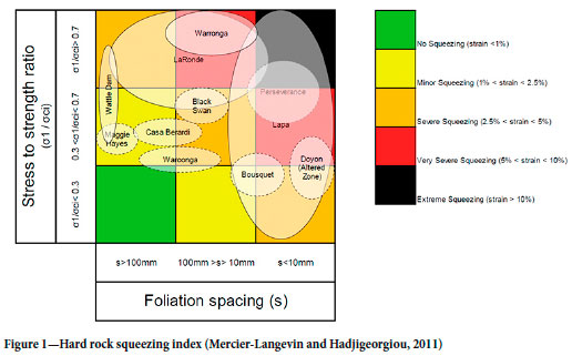
An important development since the Squeezing Task Force was the Hard Rock Squeezing Index for underground mines based on case studies from operations in Australia and Canada (Mercier-Langevin and Hadjigeorgiou, 2011). This empirical index can provide a first indication of the potential squeezing and the long-term strain level, based on foliation spacing and the stress to strength ratio, as shown in Figure 1.
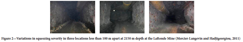
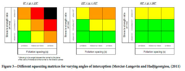
As illustrated in Figure 2, the most critical factor controlling the deformation is the orientation of the excavation with respect to the foliation. Based on a review of drifts developed at varying angles with respect to foliation and the resulting levels of squeezing, Mercier-Langevin and Hadjigeorgiou (2011) developed a series of squeezing matrices (Figure 3). The squeezing index overcomes the limitations of rock mass classification systems that assume the rock mass behaves as a continuum isotropic material.
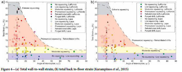
The squeezing index approach was further validated and extended from field data at the LaRonde and Lapa mines by Karampinos et al. (2015). The graphs in Figure 4 are based on some of the largest strains recorded in hard rock mines. When used for design purposes, they can indicate the highest anticipated wall-to-wall and back to floor strain for a given angle of interception.
There are several reported applications of the squeezing index in Canadian and Australian mines, including Marlow and Mikula (2013), Armatys (2012), Mercier-Langevin and Wilson (2013), and Woolley and Andrews (2015). The index is used at several mines as a prediction tool to anticipate squeezing levels for existing or anticipated changes in ground conditions. This enables proactive modifications to ground support strategies and facilitates communication to mine management regarding the increased level of anticipated squeezing.
Deformation measurements
One of the observations of the Squeezing Task Force reported by Potvin and Hadjigeorgiou (2008) was that ground deformation monitoring was inadequate or lacking at most mines experiencing squeezing ground conditions. Considerable progress has been made since then in the implementation of monitoring strategies.
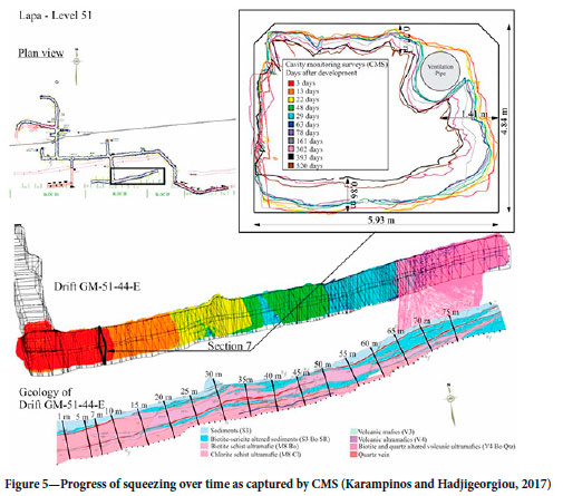
Consequently, most mines experiencing severe squeezing have now developed a good appreciation of the wall deformation as a function of time/mining activities. Figure 5 shows an example where deformation data, collected using a cavity monitoring survey (CMS), was reconciled to lithological information along a drift to better understand the evolution of squeezing over time.
A more recent source of monitoring data widely used in underground mines is based on LiDAR technology to measure the convergence of excavations with a high level of precision and high resolution (Figure 6).
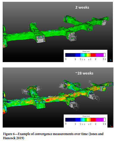
There are significant benefits from monitoring the evolution of drive convergence over time. For example, convergence measurements can be used along with damage information to calibrate numerical or empirical models. Convergence measurements can be used to provide an indication of the magnitude of observed deformations and provide an indication of the deformation potential, to assess the suitability of different ground support strategies at a specific mine site.
Numerical modelling
Numerical modelling is frequently used to reproduce or forecast the level of deformation in hard rock mines. Several publications deal specifically with squeezing rock conditions using a variety of continuum and discontinuum stress analysis models of varying complexity, e.g., Beck, Kassbohm, and Putzar (2010), Yadav and Sharan (2019), Karampinos et al. (2015). Although it is possible to calibrate a numerical model to reproduce field conditions, this is more challenging for squeezing ground.
Well-calibrated continuum models can arguably reproduce the large deformations in excavations in weak, homogeneous, and isotropic rock masses. Continuum models cannot, however, capture the observed squeezing mechanism driven by the presence of geological structures. It has been argued that explicit representation of foliation in continuum finite difference and finite element models, following extensive calibration, can potentially represent the squeezing mechanism in hard rock mines. Although continuum models can simulate comparable deformation levels to those measured in the field, they cannot allow any block rotation or relative movement of blocks, and consequently cannot capture the buckling mechanism in foliated ground.
Examples of the role of reinforcement and support using 3D continuum stress analysis models have been provided by Vakili et al. (2013) and Bouzeran et al. (2019). These types of numerical experiments are useful to understand the interaction between different parameters. Arguably, It is only though discontinuum modelling that it is possible to capture the full interaction of ground support in foliated ground conditions (Karampinos, Hadjigeorgiou, and Turcotte, 2016; Garza-Cruz et al., 2019). It is interesting to note that although in a well documented study at George Fisher Mine, Bahrani and Hadjigeorgiou (2019) demonstrated that discontinuum model resulted in a more realistic representation of the rock mass behaviour than a continuum model, they concluded at the time that running discontinuum models in this case did not meet the practical requirements for routine engineering analyses at a mine where multiple excavations are the norm.
Evolution of ground support practice
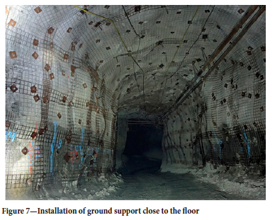
There has been significant progress in ground support practices at mine sites since the benchmarking study of 2008. For example, the majority of the mines consulted in 2008 suggested that it was not practical to reinforce the lower walls close to the floor. It is now recognized that mines can successfully install reinforcement low on the wall (Figure 7). This is reflected in the more successful ground standards for squeezing rock conditions.
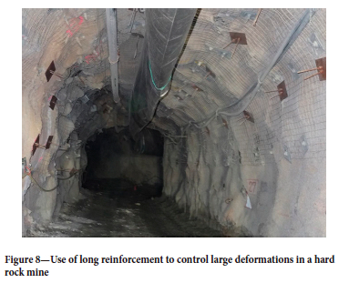
Another development has been the increasing use of cable bolts as part of the ground support standards in ore drives where large deformation is anticipated (Figure 8). However, there is no consensus whether debonding is necessary, or whether cable bolts naturally debond as they assume loading. Where the depth of fracturing extends well in the rock mass, the use of long reinforcement has been shown to be critical in controlling squeezing ground.
The other significant development is the greater availability of ground support with higher yielding or energy absorbing capacity. Since the introduction of paddled energy-absorbing rockbolts by Li (2010), different versions have become available from several suppliers. Similarly, following the application of the resin rebar hybrid bolt (Mercier Langevin and Turcotte, (2007), a resin grouted rebar installed inside a friction stabilizer, several manufacturers have developed mechanical point anchor bolts designed to fit inside a friction rockz. In addition to good yielding performance, the solid bar inside the friction bolt offers additional shear capacity that is useful in squeezing conditions (Potvin and Hadjigeorgiou, 2020). Furthermore, to overcome some of the installation issues in very fractured ground, self-drilling hollow pumpable rockbolts are beginning to receive greater attention (Knox and Hadjigeorgiou, 2023) with several types being available.
Another development is the recognition at several mines experiencing severe squeezing conditions that rehabilitation may be inevitable. This has led to considering planned rehabilitation as part of the overall ground support strategy to minimize disruption to the operation.
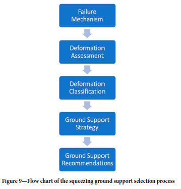
Framework for ground support guidelines in squeezing ground
In order to facilitate the design process, a ground support guidelines framework has been developed. The five steps in developing the guidelines are illustrated in the schematic in Figure 9. Each step is discussed in detail in the following sub-sections, culminating in a series of ground support guidelines for a range of squeezing ground conditions.
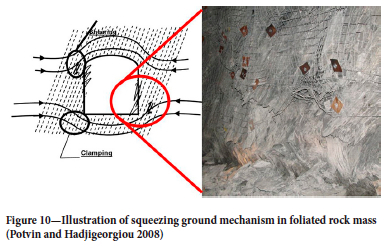
Identify the squeezing failure mechanism (step 1)
The first step is to determine the failure mechanism as this will have a significant impact on ground support requirements. Based on the authors' involvement during the last 15 years with squeezing ground conditions in metalliferous mines from around the world, it is concluded that there are two prevalent failure or squeezing mechanisms. The most common relates to highly anisotropic rock masses, or foliated ground, which results in severe buckling of the walls, when the drives run parallel to the foliation (Figure 10).
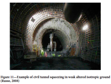
The second, and less common mechanism in mining, occurs in isotropic rock masses where the intact rock is very weak or heavily altered. In these cases, the joint matrix may also result in very broken ground and small block sizes. Under elevated stress, the drive tends to experience heavy radial shearing, with high convergence and bulging of walls (Figure 11) without the distinct deformation pattern of opposite corners of foliated ground.
The significance of being able to identify the failure mechanism cannot be underestimated. This will dictate the choice of analytical, empirical, and numerical tools that are appropriate for the observed mechanism.
Deformation assessment (step 2)
It is important to assess the magnitude of anticipated deformation in order to adopt the correct ground control management strategy and select an adequate ground support system. It is recognized that the ground support system behaviour must match the rock mass response to mining activities. More specifically, the displacement capacity of the reinforcement and surface support must be able to accommodate the rock mass deformation. Hence, forecasting the deformation is a critical step in developing ground support guidelines.
Deformation can be forecast using empirical methods, numerical modelling approaches, or simply by local experience based on convergence measurements. Industry experience indicates that if the displacement of the supported rock mass is expected to exceed 300 mm from the walls or back, ground support rehabilitation will be required.
Deformation classification (step 3)
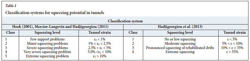
Potvin and Hadjigeorgiou (2008) summarized several classification systems to describe the level of squeezing in tunnelling. Mercier-Langevin and Hadjigeorgiou (2011) adopted the system proposed by Hoek (2001) for mining applications. However, it was recognized that there was a need for greater granularity for mining excavations that displayed convergence exceeding 10%. This led to a revised guideline by Hadjigeorgiou et al. (2013) where 10-35% strain was defined as pronounced squeezing, and extreme squeezing as more than 35% strain (Table I).
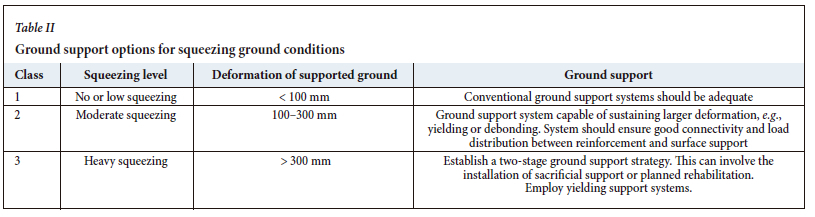
The use of a squeezing classification system, as in Table I, based on strain magnitude facilitates comparison between excavations of different size. For the purposes of selecting ground support to match the anticipated deformation level in mining drives it is possible to further simplify the process. Table II provides a simplified approach that can be used to establish suitable ground support strategies as a function of anticipated deformation of the ground support as a result of squeezing.
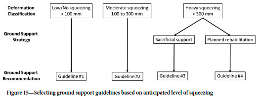
It is recognized that conventional ground support elements cannot survive deformations greater than 100 mm. This would be described as 'no or low squeezing' ground conditions. When deformation exceeds 100 mm (moderate squeezing), a ground support system capable of sustaining larger deformation is required. This would involve installing yielding reinforcement elements that use debonding or other elongation enhancement mechanisms. The success of the ground support system is dependent on strong connection between the reinforcement and surface support elements. It is the experience of most mines working in squeezing ground conditions that ground support systems generally will not survive deformation larger than 300 mm (heavy squeezing). In this case, the support strategy should account for at least one pass of rehabilitation.
Ground support strategy
For low and moderate squeezing conditions, the support strategy is to avoid rehabilitation by designing a ground support system capable of sustaining rock mass deformation up to 300 mm. In heavily squeezing ground, however, rehabilitation is generally inevitable given current ground support practice. Taking this into consideration it is important to plan for rehabilitation so that it can be completed with minimal disruption to the operation.
There are three phases of deformation generally encountered when mining in squeezing ground (Figure 12). The first phase initiates immediately after the development round is taken (a). Convergence is rapid at first and slows down with time (segments a to b). It is estimated that total wall convergence from this first episode could be in the order of 0.5 m and that the layer of the broken zone inside the wall can extend to around 2 m. The second phase of convergence (segments b to c in Figure 12) is characterized by slow to very slow convergence that is generally controlled by the installed ground support system. This convergence phase lasts until stoping nearby is undertaken (c), which initiates the third phase of deformation. Total convergence during the third phase can be in the order of 1.5 m (1 m in addition to the previous 0.5 m) and the thickness of the broken zone can extend up to 6 m in total (another 4 m added from the initial deformation phase), point (d).
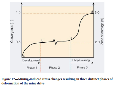
There are two fundamental ground support strategies that can be used to manage convergence due to development and stope mining. The first strategy requires the use of 'sacrificial support' and relies on installing the initial ground support system with the intent for it to absorb most of the first phase of deformation (between points a and b in Figure 12) triggered by development mining. The sacrificial ground support is then stripped towards the end of phase 1, purging the broken rock mass, and installing a stronger and more deformation resistant ground support system. The intent is for the rehabilitated ground support system to be capable of sustaining the anticipated deformation of phases 2 and 3 triggered by stope mining. Therefore, the success of the sacrificial support strategy depends on the deformation capacity of the rehabilitated support system versus the intensity of convergence during phase 2 (duration and slope between points b and c) and phase 3 (between points c and d) in Figure 12.
From a practical perspective it is advisable that the sacrificial support system is designed to be easily rehabilitated. Common strategies involve the use of friction rock stabilizers (e.g., split sets), mesh, as well as cable bolts. Fibre-reinforced shotcrete is avoided, as it is difficult to rehabilitate. The tail portion of the cable bolts remains in place after rehabilitation and provides pre-reinforced support as the ground is being stripped. It may be necessary to rehabilitate twice if the first pass of rehabilitation is completed too early within the first phase and the rehabilitated support does not survive the second phase of deformation.
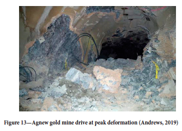
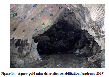
A second strategy of 'planned rehabilitation' involves scheduling rehabilitation of the ground support as soon as possible before the third phase of deformation commences when nearby stopes are extracted. The initial support system must cater for deformation for the duration of phases 1 and 2 (from points a to c in Figure 12), allowing the serviceable life of the ground support system to extend to the stope mining phase. Andrews (2019) provides a successful example of planned rehabilitation scheduled and completed just prior to longhole stoping at Agnew gold mine (Figures 13 and 14).
Ground support guidelines
Potvin and Hadjigeorgiou (2008) concluded the benchmarking study by recognizing that there is no unique solution to controlling large-scale deformations in rock. However, based on developments during the last 15 years, it is possible to provide some practical guidelines for squeezing ground. The design process illustrated in Figure 15 and the proposed guidelines discussed in this section are based on the deformation classification in Table II.
It is anticipated that there will be some variations in the described guidelines from mine to mine, This is understandable given local experience and practice. The principles, however, behind these recommendations seem to be quite universal among mines dealing successfully with squeezing ground.
Low or no squeezing: Guideline 1
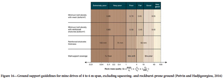
There are no specific guidelines for low or no squeezing ground conditions. Under these conditions the normal ground support standards from the mine should apply. An example of ground support guidelines for normal ground conditions, i.e. excluding squeezing- and rockburst-prone ground, has been provided by Potvin and Hadjigeorgiou (2016) (Figure 16).
The ground support guidelines were developed based on a comprehensive review of ground control management plans in Australia and Canada. These countries use the Q rock mass quality index (Barton, Lien, and Lunde, 1974) to characterize the ground conditions and specifically exclude squeezing or rockburst conditions that may require the use of yielding ground support systems.
Moderate squeezing: Guideline 2
Moderate squeezing is defined as when the anticipated displacement of any supported walls is between 100 and 300 mm. The aim of ground support under these conditions is to mitigate the need for rehabilitation. There are two main approaches that can be pursued depending on the choice of surface support, i.e., whether to apply fibre-reinforced shotcrete.
Figure 17 gives an example of a ground support guideline for moderate squeezing conditions using fibre-reinforced shotcrete as surface support. This involves the application of 50 mm of fibre-reinforced shotcrete floor-to-floor and in-cycle. The minimum specifications for the fibre-reinforced shotcrete are 32 MPa UCS and over 450 J toughness at 40 mm deflection as defined in ASTM C1550-12 (2012).
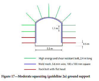
This guideline requires the installation of high energy capacity rockbolts and mesh (down to 0.5 m from the floor) over fibrecrete with a bolt density of approximately 0.65 bolts per m2 (1.1 x 1.4 m). Typical reinforcement includes hybrid bolts, paddled energy-absorbing rockbolts, and debonded bolts, The bottom two rows of bolts should have a flat head (e.g., friction stabilizers) to minimize damage to the ground support by mining equipment.
Another strategy for moderate squeezing ground is to employ mesh, as opposed to fibre-reinforced shotcrete, as the principal surface support (Figure 18). This involves the installation of high energy capacity rockbolts and mesh (down to within 0.5 m of the floor), approximately 0.8 bolts per m2 (1.1 x 1.2 m). Rockbolt options include hybrid bolts, paddled energy-absorbing rockbolts, or debonded bolts. In order to mitigate damage to the ground support by mining equipment it is recommended that the bottom two rows of bolts should have flat heads.
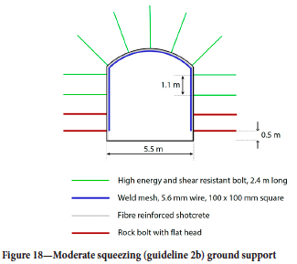
If the guidelines for moderate squeezing ground conditions (Figures 17 and 18) are not successful in mitigating the need for rehabilitation, it is recommended to increase bolt density to approximately one bolt per m2. In addition, the use of straps and/ or 6 m long twin/plain strand cable bolts can provide a more robust ground support system.
Heavy squeezing - Sacrificial support strategy: Guideline 3
Under heavy squeezing conditions, empirical evidence suggests that rehabilitation is inevitable. This imposes an additional constraint on the selection of a first-pass ground support system. For example, shotcrete applied in the first pass is difficult to rehabilitate. The objective of a first-pass system is to keep the excavation operational up to 300 mm displacement from any walls. When wall displacement reaches 200-300 mm, or before a nearby stope is extracted, rehabilitation is implemented. The two-pass system is summarized below:
First-pass ground support for heavy squeezing ground (Figure 19):
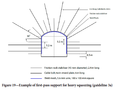
> Install 2.4 m friction rock stabilizers (46 mm diameter) at approximately 0.7 bolts per m2 density (approximately 1.2 x 1.2 m). If the intent is to further delay rehabilitation work it may be advantageous to install high-energy capacity bolts, such as hybrid rockbolts, or paddled energy-absorbing bolts. The bottom row of bolts should be within 0.3-0.5 m of the floor.
> Install 5.6 mm wire, 100 mm square mesh down to the floor
> Install 6 m long cable bolts twin strands/plain, approximately 0.3 bolts per m2 (approximately 1.5 x 2.0 m). Installation of cables lags (12-50 m) to allow initial displacement.
The combined bolt density (cables 0.3 bolts per m2 and rockbolts 0.7 bolts per m2) of the first pass is approximately 1.0 bolts per m2. Rehabilitation is generally required when any wall displacement reaches 200-300 mm. An ongoing rehabilitation schedule and priority list is maintained.
Second-pass (rehabilitation) involves the following actions (Figure 20):
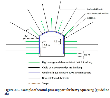
> Strip the drive wall(s) to approximately 1.5 m depth.
> Apply 50-75 mm fibre-reinforced shotcrete (32 MPa UCS and 450 J toughness at 40 mm displacement) floor-to-floor. Install high-energy capacity and shear-resistant bolts e.g., hybrid bolts or paddled energy-absorbing rockbolts, approximately 0.7 bolts per m2. Apply mesh floor-to-floor over fibrecrete. The bottom two rows of bolts are flat head bolts. Use mesh straps (or Osro straps) at mesh overlaps.
> Spray a thin protective layer of shotcrete over mesh, from 1.5 m high down to the floor.
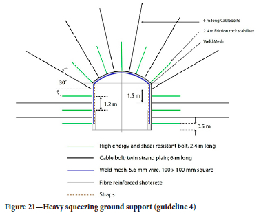
Heavy squeezing - Planned rehabilitation: Guideline 4
Despite the anticipated heavy squeezing, the aim is still to ensure that there will be no disruption to mining. The initial support should keep the drive serviceable up to just before stope mining begins (Figure 12), when rehabilitation is scheduled to occur.
> Apply 50-75 mm fibre-reinforced shotcrete (32 MPa UCS and 450J toughness, at 40 mm displacement) floor-to-floor and in-cycle.
> Install high-energy and shear-resistant rockbolts, approximately 0.7 bolts per m2, and mesh down to the floor over fibrecrete. The bottom row of bolts should be within 0.3-0.5 m of the floor.
> Use 0-gauge mesh straps (or Osro straps) at mesh overlaps, reinforced with cable bolts.
> Install 6 m long twin/plain strand cable bolts, approximately 0.3 bolts per m2. The installation of cables should lag behind (12-50 m) to allow the initial displacement of excavation. The cable bolts should preferably be installed using large plates with two hole for double barrel and wedges (e.g., Figure 8).
> Spray over the mesh a thin protecting layer of shotcrete, from 1.5 m to floor (Figure 21). If the shotcrete protection layer is not adopted, consider using flat head bolts for the bottom one or two rows of bolts.
If the damage before the planned rehabilitation is tolerable, it may be more effective not to repair immediately (Andrews, 2019). Ideally, rehabilitation is scheduled to be implemented just before localized stress changes from mining nearby stopes occur (Figure 12). It is good practice to establish rehabilitation priorities and ensure that the rehabilitation schedule is adhered to.
Conclusions
There has been significant progress in our understanding of how to best manage very large deformations in underground hard rock mines. A critical understanding of the squeezing rock mechanism is vital in selecting the appropriate analysis and design tools.
A greater emphasis on monitoring the deformation can provide a reliable estimate of the severity of squeezing as well as the effectiveness of mitigating ground support measures. This is particularly useful in deciding the optimal time for rehabilitation.
It is now recognized that there are significant advantages in using yielding ground support as well as long reinforcement. Mines have also demonstrated that they can install ground support to the floor, which was identified as a major weakness in the past (Potvin and Hadjigeorgiou, 2008).
The plethora of new ground support elements provides significant choices to mining operations. As more data becomes available on their field performance it will be possible to continue to modify the ground support strategies.
The ultimate goal is to design and install a cost-effective ground support system that will not require rehabilitation. Currently there are two pragmatic options in severe squeezing ground. The first strategy involves the use of sacrificial ground support and the second involves planning the timing of rehabilitation. In this context, quality site-specific deformation data can contribute to identifying the optimal timing for installation/rehabilitation of ground support.
Acknowledgements
The authors are grateful for the opportunity to work with multiple mines experiencing squeezing problems over the last twenty years. The benchmarking study was funded by the Ground Support Systems Optimisation Phase 2 research project at the Australian Centre for Geomechanics, University of Western Australia. Project sponsors were Agnico Eagle LaRonde mine, BHP Olympic Dam mine, DSI Underground, Epiroc, New Concept Mining, Fero Strata Australia (now DSI Underground), Garock Pty Ltd, Gold Fields Australia Pty Ltd, IGO Limited, IAMGOLD Corporation, Westwood mine, Jennmar Australia, the Minerals Research Institute of Western Australia (MRIWA), Newcrest Mining Limited, Cadia Valley Operations, and Sandvik Australia Pty Ltd.
References
Andrews, P.G. 2019. Ground support selection rationale: A Gold Fields perspective. Proceedings of the Ninth International Symposium on Ground Support in Mining and Underground Construction. Hadjigeorgiou, J. and Hudyma, M. (eds). Australian Centre for Geomechanics, Perth. pp. 15-28. [ Links ]
Armatys, M. 2012. Modification des Classifications Géomécaniques pour les Massifs Rocheux Schisteux. Master's thesis, École Polytechnique de Montréal, Montreal. [ Links ]
ASTM C1550-12. 2012. Standard test method for flexural toughness of fiber reinforced concrete (using centrally loaded round panel), ASTM International, West Conshohocken, PA. [ Links ]
Bahrani, N. and Hadjigeorgiou, J. 2018. Influence of stope excavation on drift convergence and support behavior: insights from 3D continuum and discontinuum models. Rock Mechanics and Rock Engineering, vol. 51, no. 8. pp. 2395-2413. [ Links ]
Barton, N., Lien, R., and Lunde, J. 1974. Engineering classification of rock masses for design of tunnel support. Rock Mechanics and Rock Engineering, vol. 6, no. 4. pp. 189-236. [ Links ]
Beck, D.A., Kassbohm, S., and Putzar, G. 2010. Multi-scale simulation of ground support designs for extreme tunnel closure. Proceedings of the Second International Symposium on Block and Sublevel Caving. Potvin, Y. (ed.). Australian centre for geomechanics, Perth. pp. 441-453. [ Links ]
Bouzeran, L., Pierce, M., Andrieux, P., and Williams, E. 2019. Accounting for rock mass heterogeneity and buckling mechanisms in the study of excavation performance in foliated ground at Westwood mine. Deep Mining2019: Proceedings of the Ninth International Conference on Deep and High Stress Mining. Joughin, W. (ed.). Southern African Institute of Mining and Metallurgy, Johannesburg. pp. 29-44. [ Links ]
Garza-Cruz, T., Bouzeran, L., Pierce, M., Jalbout, A., and Ruest, M. 2019. Evaluation of ground support design at Eleonore Mine via bonded block modelling. Proceedings of the Ninth International Symposium on Ground Support in Mining and Underground Construction. Hadjigeorgiou, J. and Hudyma, M. (eds). Australian Centre for Geomechanics, Perth. pp. 341-356. [ Links ]
Hadjigeorgiou, J., Karampinos, E., Turcotte, P., and Mercier-Langevin, F. 2013. Assessment of the influence of drift orientation on observed levels of squeezing in hard rock mines. Proceedings of the Seventh International Symposium on Ground Support in Mining and Underground Construction. Brady, B. and Potvin, Y, (eds). Australian Centre for Geomechanics, Perth. pp. 109-118. [ Links ]
Hoek, E. 2001. Big tunnels in bad rock. Journal of Geotechnical and Geoenvironmental Engineering, vol. 127, no. 9. pp. 726-740. [ Links ]
Jones, E. and Hancock, E. 2019. Managing the deformation of ground support and reinforcement. ACG Monitoring Performance of Ground Support Workshop, Sudbury, 22 October 2019. [ Links ]
Karampinos, E., Hadjigeorgiou, J., Turcotte, P., and Mercier-Langevin, F. 2015. Large-scale deformation in underground hard-rock mines. Journal of the Southern African Institute of Mining and Metallurgy, vol. 115, no. 7. pp. 645-652. [ Links ]
Karampinos, E., Hadjigeorgiou J., Hazzard J., and Turcotte P. 2015. Discrete element modelling of the buckling phenomenon in deep hard rock mines. International Journal of Rock Mechanics and Mining Sciences, vol. 80. pp. 346-356. [ Links ]
Karampinos, E., Hadjigeorgiou, J., and Turcotte, P. 2016. Discrete element modelling of the influence of reinforcement in squeezing conditions in a hard rock mine. Rock Mechanics and Rock Engineering, vol. 49. pp. 4869-4892. [ Links ]
Knox, G. and Hadjigeorgiou, J. 2023. Performance of conventional and energy-absorbing self-drilling hollow core rockbolts under controlled laboratory conditions. Rock Mechanics and Rock Engineering. https://doi.org/10.1007/s00603-023-03288-1 [ Links ]
Li, C.C. 2010. A new energy-absorbing bolt for rock support in high stress rock masses. International Journal of Rock Mechanics and Mining Sciences, vol. 47, no. 3. pp. 396-404. [ Links ]
Marlow, P. and Mikula, P.A. 2013. Shotcrete ribs and cemented rock fill ground control methods for stoping in weak squeezing rock at Wattle Dam Gold Mine. Proceedings of the Seventh International Symposium on Ground Support in Mining and Underground Construction. Potvin, Y. and Brady, B. (eds), Australian Centre for Geomechanics, Perth. pp. 133-148. [ Links ]
Mercier-Langevin, F. and Hadjigeorgiou, J. 2011. Towards a better understanding of squeezing potential in hard rock mines. Mining Technology, vol. 120, no. 1. pp. 36-44. [ Links ]
Mercier-Langevin, F. and Turcotte, P. 2007. Evolution of ground support practices at Agnico Eagle's LaRonde Division - Innovative solutions to high stress yielding ground. Rock Mechanics - Meeting Society's Challenges and Demands. Proceedings of the 1st Canada-US Rock Mechanics. Symposium. Eberhardt, E., Stead, D., and Morrison, T. (eds). Taylor & Francis, Vancouver. pp. 1497-1504. [ Links ]
Mercier-Langevin, F. and Wilson, D. 2013. Lapa mine - Ground control practices in extreme squeezing ground. Proceedings of the Seventh International Symposium on Ground Support in Mining and Underground Construction. Potvin, Y. and Brady, B. (eds). Australian Centre for Geomechanics, Perth. pp. 119-132. [ Links ]
Potvin, Y. and Hadjigeorgiou, J. 2008. Ground support strategies to control large deformations in mining excavations. Journal of the Southern African Institute of Mining and Metallurgy, vol. 108, no. 7. pp. 397-404. [ Links ]
Potvin, Y. and Hadjigeorgiou, J. 2020. Ground Support for Underground Mines. Australian Centre for Geomechanics, Perth. 520 pp. [ Links ]
Russo, G. 2008. A simplified rational approach for the preliminary assessment of the excavation behaviour in rock tunnelling. Tunnels et Ouvrages Souterrains, no. 207 (May-June 2008). [ Links ]
Yadav, P. and Sharan, S. 2019. Numerical investigation of squeezing in underground hard rock mines. Rock Mechanics and Rock Engineering, vol. 52. pp. 1211-1229. [ Links ]
Wolley, C.E. and Andrews, P. 2015. Short term solution to squeezing ground at Agnew Gold Mine. Proceedings of the International Seminar on Design Methods in Underground Mining. Potvin, Y. (ed.). Australian Centre for Geomechanics, Perth. pp. 199-214. [ Links ]
 Correspondence:
J. Hadjigeorgiou
Email: john.hadjigeorgiou@utoronto.ca
Received: 21 Apr. 2023
Revised: 21 Jun. 2023
Accepted: 28 Jun. 2023
Published: July 2023

