


Services on Demand
Article
 English (pdf)
 Article in xml format
 Article references
Indicators

Related links
-
 Cited by Google
 -
 Similars in Google
Share

 Permalink
Journal of the Southern African Institute of Mining and Metallurgy
On-line version ISSN 2411-9717
Print version ISSN 2225-6253
J. S. Afr. Inst. Min. Metall. vol.123 n.6 Johannesburg Jun. 2023
http://dx.doi.org/10.17159/2411-9717/1872/2023
PROFESSIONAL TECHNICAL AND SCIENTIFIC PAPERS
Stability evaluation of room-and-pillar rock salt mines by using a flat jack technique - A case study
Y. Majeed; N. Abbas; M.Z. Emad
Mining Engineering Department, University of Engineering and Technology, Lahore, Pakistan
SYNOPSIS
Room-and-pillar mining is commonly employed for the extraction of rock salt in underground mines. Pillar stress is a major concern in these mines as it is directly related to stability and mineral recovery. In this study a flat jack method was used to measure pillar stresses in three underground rock salt mines in Pakistan. The field work included determination of in-situ stress, in-situ elastic modulus, recording of field variables (pillar length and width, height and width of opening, opening width to height ratio, extraction ratio, and overburden height) and collection of salt block samples. The geomechanical properties of rock salt (uniaxial compressive strength, Young's modulus, Brazilian tensile strength, and density) were also determined to estimate overburden stress, pillar strength, and factor of safety (both estimated and actual). It was found that the measured pillar stresses are proportional to the overburden stress values, with their magnitude ranging from 6.05 MPa to 11.97 Mpa, and the pillars were found to be stable. Regression analysis was performed to develop statistical models for in-situ stress and in-situ elastic modulus. Finally a quick guideline chart was developed to determine the suitable length of pillar for a given span and required level of safety.
Keywords: flat jack, room-and-pillar mining, in-situ stress, factor of safety, regression analysis.
Introduction
The global practice for excavating massive underground rock salt deposits is by adopting stope-and-pillar or chamber-and-pillar mining techniques, which can be applied with both regular and irregular layouts depending upon the deposit characteristics. In this method almost 40% of the material is excavated forming the rooms, whereas around 60% is left in place as structural pillars in order to support the overlying burden (Hustrulid, 2001).
Pakistan has vast deposits of Himalayan rock salt in a Precambrian sequence known as the Salt Range Formation of the Salt Range, Punjab (Shah, 2009; Baloch et al., 2012). Mining of rock salt and allied industries plays an important role in the local economy. Salt Range is located in the northern part of the province of The Punjab, extending from Tilla Jogian in the east to Warcha in the central and Kalabagh in the western portion. The Salt Range Formation is associated with a dynamic frontal thrust zone of the Himalayan mountain range. The present name of 'Salt Range Formation' was suggested by Asrarullah (1967). The same rock unit was previously called the 'Saline Series' or 'Punjab Saline Series' (Wynne, 1878; Gee, 1945). The Salt Range Formation is further classified into three units, namely the Sahwal Marl unit, Bhandar Kas Gypsum unit, and Billianwala Salt unit. The Billianwala Salt unit consists of red ferruginous marl and massive layers of rock salt having a thickness more than 650 m. This unit is exposed along the southern escarpment of the Salt Range, where underground mining of rock salt is conducted at Khewra, Warcha, and Kalabagh (Shah, 2009). The rock salt deposits are categorized as massive, with only Khewra mine containing more than 82 Mt of rock salt (Asrarullah, 1967). Khewra salt mine is the second largest in the world and the largest underground room-and-pillar mining operation in Pakistan (Baloch et al., 2012).
When underground excavations are made the original in-situ stresses are disturbed, since stresses cannot pass through the excavated voids, hence they are transferred to the adjacent rock pillars. This results in an increase in the pillar stresses due to the load of overburden above the pillars and the excavations (Brady and Brown, 2005). The stability of a pillar depends on its strength and the level of stress generated in it. Many researchers have considered pillar stress as an important parameter in room-and-pillar mine design. According to Deng et al. (2003) a good pillar design can be obtained by accurate estimation of strength to stress ratio. Salamon and Munro (1967) studied 125 pillar failure cases to estimate pillar safety factor (ratio of pillar strength to pillar stress). Similarly, Bieniawski (1968) formulated equations for pillar strength calculations by performing tests on samples of various sizes ranging from 0.75 in. to 2 m. The pillar strength can be estimated by employing Equation [1]:
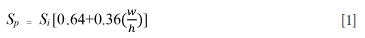
where Sp = strength of pillar, Si = strength of a specimen measured in the laboratory, and  the width to height ratio.
The in-situ pillar stresses can be quantified by using two approaches, namely a theoretical approach and on-site experimentation. It is noteworthy that unlike many other uniform materials, rocks and earth materials contain a lot of natural complexities like joints, faults, groundwater etc. These complexities offer many challenges in the correct estimation of pillar stresses (Sebastiani et al., 2015). Generally a theoretical approach to estimate the in-situ stress considers it as unit weight of the rock (γ) times the depth of overburden (Z). Many researchers (Hoek, Kaiser, and Bawden, 1995; Salamon and Munro 1967; Hedley and Grant, 1972; Krauland and Soder 1987) have used the tributary area method to determine the expected average pillar stress. According to the tributary area theory the pillar stress is not only a function of the rock above it, but also the load over the excavated area. As per Brady and Brown (2005) the load of overburden material above an excavation is shared by the pillars on the either side of excavation. Brady and Brown (2005) formulated the following equation based on the tributary area theory.
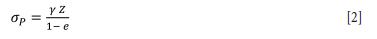
where σΡ denotes the in-situ stress acting on the pillar, γ is the unit weight; Z is the depth below surface, and e is the extraction ratio.
For real-time on-site stress measurements in mines, various techniques have been developed including hydraulic fracturing, overcoring, and flat jack. Hydraulic fracturing is particularly employed in the petroleum engineering industry for the measurement of ground stresses. In 1960, this method was used for stress assessment in productivity stimulation. There are now two major categories of this technique, namely conventional hydraulic fracturing and hydraulic tests on pre-existing fractures (HTPF). Bell and Gough (1979) proposed the traditional concept of borehole breakout stress orientation by interpreting the stress field around the borehole using Kirsch's solution. Overcoring is another common stress measurement technique, especially utilized in the geotechnical industry (Feng, Harrison, and Bozorgzadeh, 2020). The calculation is based on the deformation of a pilot hole. This technique delivers high-accuracy stress measurements and can be used in a variety of geological situations (Lin et al., 2018). Details regarding hydraulic fracturing and overcoring techniques can be found in the literature (Obert and Duvall 1967; Jumikis, 1983; Goodman, 1989; Hoek and Brown, 2005; Brady and Brown, 2005; Lamas, Muralha, and Figueiredo, 2010; Eberhardt and Stead, 2011).
The flat jack technique of in-situ stress measurment is particularly employed in the mining industry. The idea is to use the pressurization of a flat jack in a slot to calculate stress. Strain gauges are used to continually measure two points A and B, and a slot is cut adjacent to the measurement points. A flat jack is then put into the slot and compressed until the distance between A and B is restored to its previous value. The cancellation pressure at this point is believed to represent the average normal stress over the slot, and the stress field can then be evaluated. According to Gregorczyk and Lourenco (2000) the stress test results are interpreted converting jack pressure to the in-situ compressive stress. This method is simple, inexpensive, and straightforward to implement, and it does not require an elastic modulus for calculation. On the other hand there are some limitations of this method:
> Measurement of average stress orthogonal to the surface of the test slot
> For jack tests the rock mass is assumed to be isotropic and homogenous
>- In highly cracked or shattered rock materials the relief of stress may not be completely reversed (ASTM, 2008)
> The flat jack is only useful at the excavation's surface where the rock is close to being overstressed (Lin et al., 2018).
Flat jack is one of the reliable technologies that have been used by many researchers in measuring in-situ stresses in mining and civil structures. Comprehensive information on flat jack testing can be found in the relevant literature (Bieniaweki, 1981; ISRM, 1986; Binda and Tiraboschi, 1999; Gregorczyk and Lourenco, 2000; Fedele and Marier, 2007; ASTM, 2008; Verstricht et al., 2010; Lamas, Muralha, and Figueiredo, 2010; Figueiredo, Lamas, and Muralha, 2010, 2011; Simoes et al., 2012; Dhawan, 2012; Sabri, Ulybin, and Zubkov, 2015; He and Hatzor, 2015; Cescatti et al., 2016; Latka and Matysek, 2017; Mendola, Giudice, and Minafo, 2019; Selen et al., 2020; Corkum, 2020; Armanasco and Foppoli, 2020; Rios and O'dwayer, 2020; Medeiros, Soriani, and Parsekian, 2020, amongst others)
Pakistan produces around 3,193,791 Mt of rock salt per annum (Mines and Minerals Department, 2020). Due to the massive nature of the deposits, mines have mostly multi-level operations developed using the stope-and-pillar method with regular layouts. For example, the Khewra salt mine, rated as second largest mine in the world, has 17 working levels. The annual production is about 465,000 t and the expected mine life is around 350 years (Baloch et al., 2012). Due to the multi-level underground operations the in-situ pillar stresses are important for the stability and integrity of mine structure.
This research study is focused on determining vertical stress levels in rock salt pillars at three selected salt mines located in the Salt Range, Punjab. Stress measurements were performed in pillars with the help of the flat jack method, and on-site challenges associated with its use are also discussed. The stability of selected rock salt mines was evaluated by using actually measured stresses as well as empirically estimated pillar stress and strength values. Moreover, the effect of pillar dimensions on mine stability was investigated based on the factor of safety approach.
Research methodology
The research work consisted of field work and laboratory investigations along with computations of pillar strength and in-situ stress using an empirical approach.
Field work
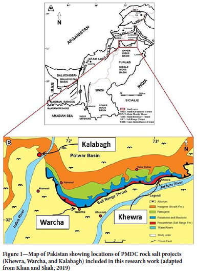
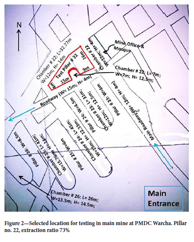
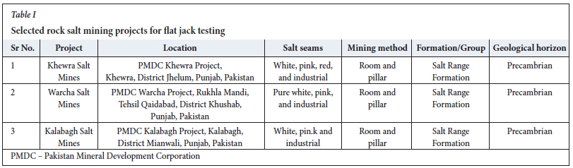
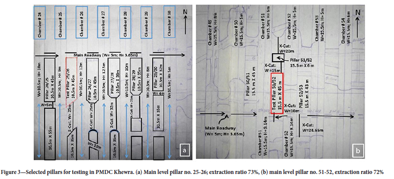
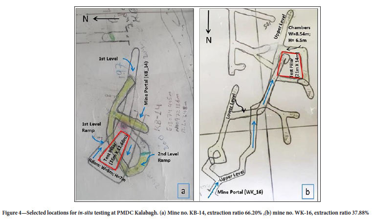
The field studies included real-time in-situ stress measurements using the flat jack technique, study of underground mine plans, and collection of representative blocks of rock salt for subsequent laboratory studies. Three rock salt mining projects operated by M/s. Pakistan Mineral Development Corporation (PMDC), namely Khewra, Warcha, and Kalabagh, located in the eastern, central, and western regions of the Salt Range, were selected (Figure 1). Table I lists the selected projects along with their locations, geological environment, and age (Shah, 2009). At each mine suitable pillars for flat jack testing were selected based on the underground mine plans, pillar geometry, rock salt type, overburden height, and distance from the mine portal. Figures 2, 3, and 4 show the mine plans of PMDC Warcha, Khewra, and Kalabagh projects respectively, illustrating the test pillars selected for performing flat jack tests along with mine geometry and extraction ratio. At PMDC Warcha project (Figure 2) the pillar width varies from 4.5 m to 10 m and the width of the chambers ranges from 12 m to 16 m. The height of chambers varies from 4 m to 16.5 m, with an average mining height of 12.2 m. The PMDC Khewra project has two mine plan configurations, comprising 10.5 m (Figure 3, left) and 15.5 m (Figure 3, right) wide rooms and pillars. The height of openings varies from 3.65 m to 12.50 m. It is worth mentioning here that Khewra has adopted the layout with 15.5 m wide rooms and pillars for its current and future workings. The mine layout at PMDC Kalabagh project (Figure 4) comprises 14 m wide pillars and rooms with 8.5 m width and 7 m height. Before proceeding with the flat jack tests, the specific locations on selected pillar ribs were checked for material competence and the presence of any micro- and macro-flaws by visual inspection and sonic testing using blows with a geological hammer.
Field experimental set-up
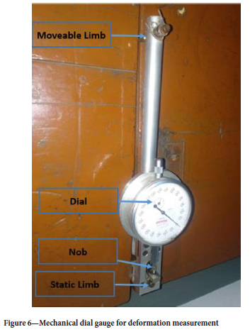
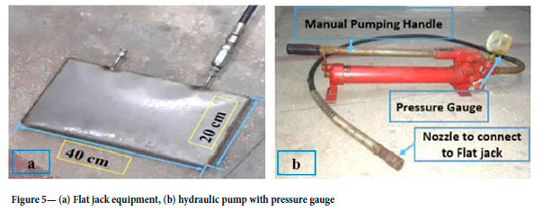
The in-situ stress measurement set-up comprised a flat jack, hydraulic pump, and deformometer (a device to measure length variation). A locally manufactured flat jack (length 40 cm; width 20 cm; thickness 1.5 mm) with maximum operating pressure of 400 bars was used (Figure 5a). It consisted of two steel plates (20/10 plate thickness) welded together along the edges using high-strength acetylene-assisted welding. Two steel tubes with 6 mm outer diameter and 3 mm inner diameters were introduced to pressurize the flat jack with hydraulic oil, one tube for the attachment with the hydraulic pump and the other to connect an extra flat jack if used, otherwise plugged. The hydraulic pump was a single-stage hand pump with reservoir with a pressure gauge of 700 bar range and flexible hose for connection with the flat jack (Figure 5b). A mechanical dial gauge deformometer was used to measure the rock deformation as shown in Figure 6. It consists of three components, namely the dial gauge, moveable limb, and static limb or scale. The static limb is fixed while the moveable limb gives a measuring range of 5.00 mm. The instrument can be used to measure deformations in rock with an accuracy of 0.001 mm.
On-site challenges
Site selection was a major challenge as pillar stress was determined in the middle of the mine instead of a test gallery. The testing required an undisturbed rock surface with an electrical connection nearby. In addition, the site had to be safe and away from operational activities. The flat jack testing requires a lateral slot to be cut in the rock, which is a challenging task. Generally, the slot can be developed using overlapping or contiguous drill-holes, a disc cutter, or chainsaw. In this work the slot was cut using contiguous drill-holes due to the relatively soft rock conditions. The other two methods of slot creation (disc cutter and chainsaw cutter) are usually preferred in hard rock. The disc cutter can be used on site with an appropriate mounting assembly, which enables lateral movement of the cutter, thus creating a slot. The cutter must have a large enough diameter to cut a deeper slot. If a chainsaw is employed for slot cutting, the cutting tips must be customized for use in softer and corrosive rocks such as rock salt. Overall, the locally manufactured flat jack equipment used in this research work was handy in terms of flexibility, with specifications making it robust for site conditions. It was also cheaper than the commercial solution available. The only catch was its calibration and validation of the tests performed. The calibration was performed in the laboratory as suggested by Mendola, Giudice, and Minafo (2019).
Flat jack calibration
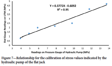
The pressure exerted by the flat jack on the walls of the slot is indicated by the pressure gauge of the hydraulic pump. Therefore in order to perform precise in-situ stress measurements the pressure gauge was calibrated using the pre-calibrated read-out gauge/ unit of the laboratory 200 t Schimadzu universal testing machine (UTM). For this purpose the flat jack was placed between the platens of the UTM under a known applied force. Then the pressure in the flat jack was increased in increments of 11 kg/cm2 and at each increment the dial gauge reading of the hydraulic pump and corresponding reading of the UTM gauge were noted. Finally, a relationship was developed (Figure 7) to calculate the calibrated stress value using the stress value indicated by the pressure gauge of the flat jack hydraulic pump.
In-situ stress measurement
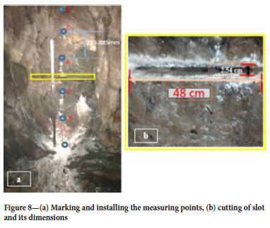
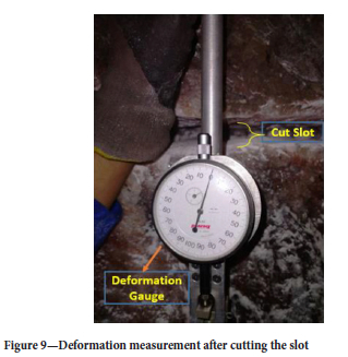
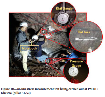
The in-situ flat jack tests were performed according to the test procedure provided in Brady and Brown (2005). In the selected pillar rib, the location for evaluating rock deformation was prepared by installing three sets of measuring pins (Figure 8a) on each side along the centreline orthogonal to the axis of the pre-marked flat jack slot. The distance between the measuring points was accurately measured by using a highly sensitive dial-gauge deformometer with an accuracy of 0.001 mm. A slot approximately 48 cm wide was cut (Figure 8b) using a hand-held rock-drill machine to drill contiguous holes of 25 mm diameter. After cutting the slot, the distance between the installed pins was measured again in order to determine the amount of slot closure (Figure 9). The difference between the measured distances before and after slot cutting is the deformation of rock around the slot. Finally, the flat jack was fully inserted into the slot and hydraulic pressure was applied in increments of 20 kgf/cm2 utilizing a manual hydraulic pump capable of exerting a pressure of up to 700 bar. The cancellation pressure at which the measurment points shifted to their original positions was noted from the pressure gauge on the hydraulic pump. Figure 10 illustrates an integrated view of in-situ stress measurement carried out at PMDC Khewra (pillar no. 51-52). During experimentation reversals of axial deformations were also noted after every 20 kg/cm2 increment of hydraulic pressure. This data was utilized to plot axial stress versus axial strain and ultimately in-situ moduli of elasticity were determined for all the selected pillars.
Computation of pillar strength and stress
The average pillar strength and stress were determined by employing the tributary area method (Brady and Brown (2005) for rectangular room-and pillar-layout. According to this approach the load of the overlying strata is equally distributed among the pillars. The pillar strength for rock salt mines was computed by using Equation [3] (Mao, 2015). It is pertinent to highlight here that Equation [3] is a modified version of Bieniawski (1968, Equation 1) which was originally developed for coal pillars only. Similarly the pillar stress was computed by using Equation [4] (Brady and Brown, 2005). Finally, the factor of safety (FOS) was computed both for actual in-situ pillar stress (measured in the field) and estimated stress scenarios.
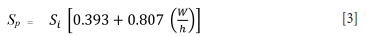
where Sp = strength of pillar. Si = strength of specimen measured in the laboratory, and  is pillar width to height ratio.
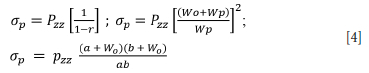
where Pzz = vertical component of pre-mining stress field, r is the extraction ratio, Wo is the span of the opening or room, Wp is the span of the pillar, and a and b are the pillar dimensions in plan view for a rectangular pillar.
Collection of rock salt blocks
To carry out laboratory scale testing, rock salt blocks were collected from all three selected mining projects according to the ASTM D2113 (2014) standards. In this regard, representative salt blocks of appropriate size (at least 12 inches edge dimensions) and free from any noticeable flaws were selected.
Laboratory testing
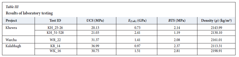
As per the research plan a comprehensive suite of laboratory experiments including uniaxial compressive strength (UCS), Young's modulus (E), Brazilian tensile strength (BTS), and density (ρ) tests were performed. Rock salt cores were obtained by drilling the collected blocks using standard NX size (54 mm) core cutting bits and cylindrical specimens were prepared according to the guidelines in the ASTM D4543 (2008) standards.
Compressive strength and elastic modulus
The UCS and uniaxial deformability tests were performed on prepared cylindrical rock salt core samples utilizing a 200 t universal testing machine. To compute the elastic moduli, axial as well as lateral strains were determined at fixed loading intervals until the sample failed. Two mechanical dial gauges having a least count of 0.01 mm were used for this purpose. The tests were carried out according to the recommendations in ASTM D7012 (2010).
Brazilian tensile strength
The BTS tests were carried out in accordance with the recommendations in ASTM D3967 (2016). Prepared discs of rock salt with thickness or height approximately equal to 0.5 times the diameter were loaded diametrically and failure loads were noted.
Density
The density of rock salt was determined from the weight to volume ratio of prepared core samples. The volume of each core specimen was determined by taking the average of height and diameter values with a Vernier caliper. A weighing balance with a least count of 0.01 g was used to determine the weight of the specimen.
Results and discussion
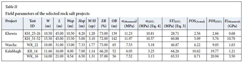
Table II lists the field variables along with actual and estimated parameters including pillar width (W), pillar length (L), width of opening (Wop), height of opening (Hop), opening width to height ratio (W/H(op)), extraction ratio (ER), overburden height (OB), in-situ pillar stress (σ(Measured)), estimated pillar stress (cT(est)), estimated pillar strength (ST(EST)), factor of safety based on in-situ pillar stress (FOS(Actual)), factor of safety based on estimated pillar stress (FOS(EST)), and in-situ Young's modulus (E(Measured)). Similarly, Table III lists the data acquired from laboratory investigations comprising uniaxial compressive strength (UCS), Young's modulus E(Lab)), Brazilian tensile strength (BTS), and density (ρ). The discussion of results is chiefly focused on performing a comprehensive pillar stability analysis for the selected rock salt projects by considering stress (in-situ versus estimated) and factor of safety (actual against measured) approaches. Moreover, statistical relationships including in-situ and laboratory elastic modulus, in-situ pillar stress versus width to height ratio of opening, as well as overburden height are also developed specifically for room-and-pillar rock salt mines. Finally, the pillar optimization analysis was performed to suggest the effective pillar length based on factor of safety for a given pillar width.
Pillar stability analysis
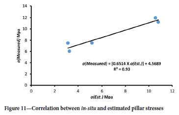
To investigate the stability of the mine layout, analysis was performed based on pillar stress and pillar factor of safety (Fes) by considering both in-situ and estimated values. It is worth mentioning here that Salamon and Munro (1967) and Bieniawski (1981) initially recommended the factor of safety (FOB) approach to evaluate the stability of underground room-and-pillar mines. A close look at Table II shows that estimated stresses for pillars KH_25-26; KH_51-52, and WR-22 are an order of magnitude higher than expected. This is attributed to deviations from the designed mine plans, especially around the test locations or pillars selected for in-situ testing. Due to over-extraction of pillars (i.e. increased width of crosscuts and high chambers) the resulting extraction ratios in respect of pillars KH_25-26; KH_51-52, and WR-22 are 73, 72%, and 73% respectively. This fact is also evident from the actual measured stress values (ff(Measured)) (Table II), which remain in a closer range to the estimated stress values([ff(EST)) and demonstrate the accuracy of field measurements. Similarly, in the case of pillars KB_14 and WK_16 (Table II) the measured stress values (ff(Measured)) are somewhat higher in comparison to the estimated stress values (ct(EST)), which may be ascribed to the complex tectonosedimentary framework of the western Salt Range (Ghazi et al., 2015). Moreover, inclined chambers are forming ramps around the test pillar, incorporating ground stresses leading to higher in-situ stresses. Figure 11 shows the relationship (R2 = 0.93) between the in-situ stresses measured in the field and those estimated using Equation [4], where an increasing linear trend can be observed. The developed relationship (Figure 11) can be applied for the estimation of in-situ stress in rock salt pillars from empirically estimated stress values.
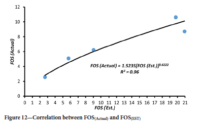
An attempt was also made to establish a possible correlation (Figure 12) between the FOS(Actual) and FOS(EST) and a power function of moderate strength (R2 = 0.96) was found. According to Jeremic (1994) FOS values of 1.0, 1.3, and 1.6 must be maintained for temporary, intermediate, and long-term underground room-and-pillar rock salt mines in order to carry out safe mining operations. The FOS(Actual) and FOS(EST) values determined in this work (Table II) are well above the recommended value of 1.6 for long-term underground mines, which indicates the stability of the layouts and allowance for pillar optimization, which will enable the extraction ratio to be increased without compromising stability.
Relationship between in-situ and static elastic modulus
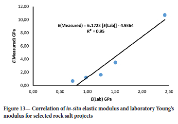
Elastic modulus (Youngs modulus) is a fundamental property that represents the stiffness of a material, i.e. how the material deforms under applied load. In underground room-and-pillar mines it is an important design parameter which indicates the likelihood of pillar failure as well as providing an evaluation of the stability of the overall layout. In this work, the elastic moduli were determined both in the field and in the laboratory. Table II shows the in-situ modulus of elasticity (E(Measured)) measured for the selected projects, whereas Table III includes the static Young's modulus (E(Lab)) measured in laboratory tests. A significant correlation (R2 = 0.95) was established between E(Measured) and E(Lab) (Figure 13). Since it is both costly and laborious to measure in-situ stress and elastic modulus, the developed conversion equation in Figure 13 can be utilized to estimate the in-situ modulus for underground room-and-pillar rock salt mines based on the laboratory-measured static Young's modulus.
Correlation of in-situ stress with room width to height ratio and overburden height
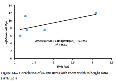
In underground room-and-pillar mining layouts, the vertical stress on pillars (due to overburden material) is dependent on the width of rooms and pillars as well as height of rooms. The opening width to height ratio [ W/H(op)] is an important parameter in studying the combined effect of these factors on the pillar stress (Hartman and Mutmansky, 2002). In the current work efforts have been made to establish a relationship between width to height ratio of the opening and actual or in-situ stress measured in the field. Figure 14 displays a linear positive correlation of moderate power (R2 = 0.41) illustrating the effect of increasing room span on pillar stress. The results are in full conformity with past investigations (Hartman and Mutmansky, 2002; Lau, 2010).
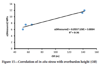
The effect of height of overburden material on in-situ pillar stress was also investigated. Room-and-pillar mining in a massive orebody like rock salt causes redistribution of the load, which results in an increase of stress concentration on the supporting pillars (Brady and Brown, 2005). A plot of overburden height (OB) against the actual in-situ stress measured in the pillar ribs for the selected mine sites yields a positive increasing trend with a high coefficient of determination (R2 = 0.96, Figure 15). The correlation so developed is specific to rock salt mines of the Salt Range, and can be used for the estimation of in-situ pillar stress by using the overburden height.
Effect of pillar dimensions on mine stability
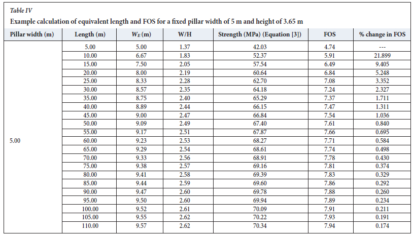
The influence of pillar dimensions on factor of safety (FOS) was investigated for the selected rock salt mines based on the average values of rock salt properties [σ(Measured), UCS] for the calculations of FOS included in Tables II and III. This pillar optimization analysis was performed by keeping the height of pillars the same as those in the actual field situations (3.65 m) and varying the width and length of pillars. In the case of rectangular pillars, equivalent pillar length was determined by using Equation [5] as suggested by Wagner 1974).
where; WE = equivalent length, A = area of pillar, and C = perimeter of the pillar.
Table IV shows an example calculation for a pillar width fixed at 5 m and various pillar lengths from 5 m to 110 m. In a similar way, equivalent lengths and FOS calculations were performed for pillar widths of 10, 15, 20, and 25 m. Figure 16 shows the relationship between pillar effective length and FOS for selected pillar widths.
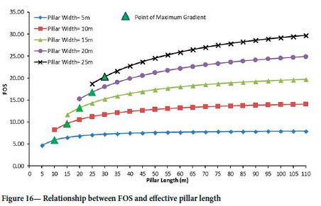
It is interesting to note from Figure 16 that initially the FOS increases with increasing in pillar length, but the influence on FOS becomes negligible when the length of pillar is increased beyond a certain limit. This limit is termed here the maximum effective length (MEL). It is evident from Figure 16 that a pillar length beyond MEL is responsible only for lowering the extraction ratio and sterilizing mineral resources. Similarly, optimum length (Figure 16) is that which falls at the point of maximum gradient on the FOS versus pillar length curves for the selected pillar widths and is the most suitable length in terms of obtaining the maximum extraction ratio. Keeping these facts in view, the generic chart (Figure 16) can be used to determine the most efficient layout of rock salt pillars without compromising the extraction ratio and stability of the mine for a planned pillar width. As can be seen in Figure 16, a pillar of 5 m width should not be longer than 20 m in order to obtain maximum extraction and safety. All other layouts are conservative designs and can be amended for maximum extraction. The curves proposed in Figure 16 are applicable for rock salt mines in the Salt Range with similar rock and mine conditions.
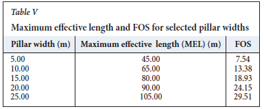
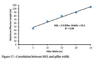
In order to find the maximum effective length (MEL) of a pillar the percentage FOS difference (computed for each increment of 5 m in pillar length) is adopted by setting the cut-off value at 1.00. For example, in Table IV for a pillar width of 5 m, the values of pillar length and FOS at predetermined cut-off grade are 45 m and 7.54 respectively. In addition to the generic chart (Figure 16), a regression equation is proposed to predict MEL based on the pillar width. Table V lists down the data values (FOS and maximum effective pillar length) corresponding to the cut-off value of 1.00 for the selected pillar widths of 5, 10, 15, 20, and 25 m. Figure 17 shows the regression plot and correlation between MEL and pillar width.
Conclusions
Pillar stability was investigated at three underground rock salt mining projects operated by Pakistan Mineral Development Corporation (PMDC) in the Salt Range of Punjab, Pakistan. The first part of this study comprised field work and included actual in-situ pillar stress (σ(Measured)) measurements conducted on suitable pillar locations using a flat jack, determination of in-situ modulus of elasticity (E(Measured)), and recording of mine geometry parameters. This data was further utilized to estimate empirically the pillar stress (σ(EST), Equation [4]). The second part of the study consisted of rock mechanics laboratory testing in order to estimate pillar strength (ST(EST), Equation [3]). The physico-mechanical properties of rock salt considered were uniaxial compression strength (UCS), Brazilian tensile strength (BTS), Young's modulus [E(Lab)), and density (ρ). Finally, safety factors of pillars for both actual and estimated scenarios were calculated. The following conclusions can be drawn from the results.
> The pillar stabilities for the selected mines were checked based on pillar stress and pillar factor of safety (FOS) by considering both in-situ and estimated values. The in-situ pillar stresses (Table II) were found to be 11.60 MPa, 7.53 Mpa, and 6.78MPa at Khewra, Kalabagh, and Warcha salt mining projects respectively. The estimated stresses in the pillars at Khewra (KH_25-26; KH_51-52) and Warcha (WR-22) were somewhat higher than expected. This is mainly due to the deviations from the mine design and pillar robbing to increase the extraction ratios. The same result was reflected from field measurements (ff(Measured)) (Table II) having values close to the estimated stresses (a(EST)). However, the measured stress values (ff(Measured)) at test pillars at Kalabagh mine (KB_14 and WK_16, Table II) were greater than the estimated stresses (ff(EST)) due to the complex regional tectonic setting of the western Salt Range and the development of ramps around the test pillar that impart lateral stresses.
> The actual and estimated values of FOS determined (Table II) for the three mines lie above the recommended value of 1.6, which indicates their long-term structural stability. Moreover, a strong linear correlation (R2 = 0.93, Figure 11) was established between the actual and estimated pillar stresses. Similarly, a power function correlation of moderate significance (R2 = 0.96) was also established (Figure 12) between the FOS(Actual) and FOS(EST).
> In view of the cost and laborious work involved in the determination of in-situ stress and elastic modulus, efforts have been made to suggest a correlation between E(Measured) and E(Lab). The application of this proposed relationship (R2 = 0.95, Figure 13) is specific for the estimation of the in-situ modulus for underground chamber-and-pillar rock salt mines based on the laboratory-measured static Young's modulus.
> In order to demonstrate the effect of opening width to height ratio (W/H(op)) and overburden height (OB) on actual in-situ pillar stress in underground conditions, two linearly increasing correlations have been developed (Figures 14 and 15) that can be used for the estimation of in-situ pillar stress for the rock salt mines of Salt Range by employing the room width to height ratio and overburden height.
> In addition, the influence of pillar dimensions on FOS (pillar optimization analysis) was investigared for the selected mines by keeping the height of pillars the same as in the actual field situations (3.65 m) and varying the width and length. It was noticed that a greater pillar length does not contribute significantly to FOS beyond a certain length, termed the maximum effective length (MEL). Therefore, it is recommended to reduce pillar length to improve the extraction ratio without compromising mine stability. Finally a generic chart (Figure 16) was developed for different pillar widths from 5 m to 25 m to determine the effective length and FOS of rock salt pillars. Furthermore, a correlation (Figure 17) was also proposed to predict MEL based on pillar width. The generic chart so developed can be used to establish a suitable length of pillar for a given span and required level of safety.
> For future work it is recommended that three-dimensional geomechanical modelling and simulation be performed using the data from this research project in order to enhancethe recovery ratio of rock salt through optimization of pillar dimensions for the rock salt mines of the Salt Range, Punjab.
Funding information
This study was funded by the Higher Education Commission (HEC), Pakistan with Grant No.9545.
Acknowledgements
The authors would like to acknowledge the support provided by the management of Pakistan Mineral Development Corporation (PMDC) at their Khewra, Kalabagh, and Warcha salt mines. Especial appreciations goes to Engr. Rana Tanveer (Project Manager) and Engr. Umer Pervaiz (Assistant Manager) at PMDC Khewra Project, Engr. Irfan Chaudhry (Project Manager), Engr. Mohsin Aziz (Assistant Manager) and Engr. Shoaib (Assistant Manager) at PMDC Kalabagh Project and Engr. Malik Naeem (Project Manager), and Engr. Imran Khan at PMDC Warcha Project. Many thanks are also due to the Department of Mining Engineering, Faculty of Earth Sciences and Engineering, of University of Engineering and Technology (UET), Lahore, for facilitating this research work.
References
Armanasco, A. and FoppoLi, D. 2020. A flat jacks' method for in situ testing of brick masonry shear characteristics. Construction and Building Materials, vol. 262.119840. [ Links ]
Asrarullah, P. 1967. Geology of the Khewra Dome. Proceedings of 18th and 19th Combined Session of all Pakistan Science Conference Part III, Hyderabad, Pakistan. [ Links ]
ASTM D4729. 2008. Standard test method for in-situ stress and modulus of deformation using flatjack method. American Society for Testing and Materials. doi: 10.1520/D4729-08 [ Links ]
ASTM D2113. 2014. Standard practice for rock core drilling and sampling of rock for site exploration. American Society for Testing and Materials. https://standards.globalspec.com/std/9885092/ASTMD211. [ Links ]
ASTM D4543. 2008. Standard practices for preparing rock core as cylindrical test specimens and verifying conformance to dimensional and shape tolerances. American Society for Testing and Materials. https://www.astm.org/DATABASE.CART/HISTORICAL/D4543-08.htm [ Links ]
ASTM D7012. 2010. Standard test method for compressive strength and elastic moduli of intact rock core specimens under varying states of stress and temperatures. American Society for Testing and Materials. https://www.astm.org/DATABASE.CART/HISTORICAL/D7012-10.htm [ Links ]
ASTM D3967 2016. Standard test method for splitting tensile strength of intact rock core specimens. American Society for Testing and Materials. https://www.astm.org/Standards/D3967.htm [ Links ]
Baloch, M., Qureshi, A., Waheed, A., Ali, M., Ali, N., Tufail, M., and Khan, H. 2012. A study on natural radioactivity in Khewra Salt Mines, Pakistan. Journal of Radiation Research, vol. 53, no. 3. pp. 411-421. [ Links ]
Bell, J.S. and Gough, D.I. 1979. Northeast-southwest compressive stress in Alberta evidence from oil wells. Earth and Planetary Sciences Letters, vol. 45, no. 2. pp. 475-482. [ Links ]
Bienlawski, Z.T. 1968. The effect of specimen size on compressive strength of coal. International Journal of Rock Mechanics and Mining Sciences & Geomechanics Abstracts, vol. 5, no. 4. pp.c325-335, doi: 10.1016/0148-9062(68)90004-1 [ Links ]
Bienlawski, Z.T. 1981. Experience with in situ measuremment of deformability. Geophysical Research Letters, vol. 8, no. 7. pp. 675-677. [ Links ]
Blnda, L. and Tiraboschi, C. 1999. Flat-Jack Test: A slightly destructive technique for the diagnosis of brick and stone masonry structures. International Journal for Restoration of Buildings and Monuments, vol. 5, no. 5. pp. 449-472. [ Links ]
Brady, B.H.G. and Brown, E.T. 2005 Rock Mechanics for Underground Mining.3ed edn. Springer, Dordrecht. [ Links ]
Brady, B. and Brown, E. 2007. Pillar supported mining methods. Rock Mechanics for Underground Mining. Springer, Dordrecht. https://doi.org/10.1007/978-1-4020-2116-9_13 [ Links ]
Cescatti, E., Benetta, M.D., Modena, C., and Casarin, F. 2016. Analysis and evaluations of flat jack test on a wide existing masonry buildings sample. Proceedings of the 16th International Brick and Block Masonry Conference, Padova, Italy. Routledge. pp. 26-30. [ Links ]
Corkum, A.M.M.A.G. 2020 Experimental evaluation of rapid flat jack testing with various shaped saw cut slots. Rock Mechanics and Rock Engineering, vol. 53, no. 1. pp. 455-466. [ Links ]
Deng, J., Yue, Z., Tham, L., and Zhum, H.H. 2003. Pillar design by combining finite element methods, neural networks and reliability: A case study of the Feng Huangshan copper mine. China. International Journal of Rock Mechanics and Mining Sciences, vol. 40. pp. 585-599. [ Links ]
Dhawan, K.R. 2012. Flat jack method for measuring design parameters for hydraulic structures of the Koyna hydro-electric project in India. ISSMGE International Journal of Geo-engineering Case Histories, vol. 2, no. 3. pp. 182-195. [ Links ]
Eberhardt, E. and Stead, D. 2011. Geotechnical Instrumentation. Mining Engineering Handbook. 3rd edn, Darling, P. (ed.). Society for Mining, Metallurgy & Exploration, Littleton, CO. pp 551-571. [ Links ]
Fedele, R. and Maier, G. 2007. Flat-jack tests and inverse analysis for the identification of stress states and elastic properties in concrete dams. Meccanica, vol. 42, no. 4. pp. 387-402. [ Links ]
Figueiredo, B., Lamas, L., and Muralha, J. 2010. Determination of in situ stresses using large flat jack tests. Proceedings of the 6th Asian Rock Mech.Symposium - Advances in Rock Engineering, New Delhi, India,, 23-27 October 2010. doi: 10.13140/2.1.3118.9762 [ Links ]
Figueiredo, B., Lamas, L., and Muralha, J. 2011. Numerical simulation of a large flat jack test with cyclic loading. Proceedings of the 6th International Conference on Dam Engineering, Lisbon, Portugal, 15-17 February. Pina, C., Portela, E., and Gomes, J. (eds). CI-Premier, Singapore. http://repositorio.lnec.pt:8080/jspui/h,andle/123456789/1002718 [ Links ]
Feng, Y., Harrison, J.P., and Bozorgzadeh, N. 2020. A Bayesian approach for uncertainty quantification in overcoring stress estimation. Rock Mechanics and Rock Engineering, vol. 54, no. 2. pp. 627-645. doi: 10.1007/S00603-020-02295W [ Links ]
Gee, E.R. 1945. The age of the Saline Series of the Punjab and of Kohat. National Academy of Sciences, India, Section B, vol. 14. pp. 269-310. [ Links ]
Ghazi, S., Ali, S.H., Sahraeyan, M., and Hanif. T. 2014. An overview of tectonosedimentary framework of the Salt Range, northwestern Himalayan fold and thrust belt, Pakistan. Arabian Journal of Geoscience. doi: 10.1007/s12517-014-1284-3 [ Links ]
Goodman, R.E. 1989. Introduction to Rock Mechanics. 2nd edn. Wiley & Sons. [ Links ]
Gregorczyk, P. and Lourenco, P.B. 2000. A review on flat-jack testing. Revista Engenharia Civil, vol. 9. pp. 39-50. https://citeseerx.ist.psu.edu/document?repid=rep1&type=pdf&doi=093cbc7d06f40d24b02fc849eb50cb-14c78629a5 [ Links ]
Hartman, H.L. and Mutmansky, J.M. 2002. Introductory Mining Engineering. 2nd edn. Wiley. [ Links ]
He, B.G. and Hatzor, Y.H. 2015. An analytical solution for recovering the complete in-situ stress tensor fpp. rom flat jack tests. International Journal of Rock Mechanics and Mining Sciences, vol. 100, no. 78. pp. 118-126. [ Links ]
Hedley, D.G.F. and Grant, F. 1972. Stope-and-pillar design for Elliot Lake Uranium Mines. CIM Bulletin, vol. 65. pp. 37-44. [ Links ]
Hoek, E., Kaiser, P.K., and Bawden, WF. 1995. Support of Underground Excavations in Hard Rock. Balkema, Rotterdam, 215 pp. [ Links ]
Hoek, E. and Brown, E.T. 2005. Underground Excavations in Rock. Revised 1st edn. Taylor & Francis. [ Links ]
ISRM. 1986. Suggested method for deformability determination using a large flat jack technique. vol. 23, no. 2. pp. 133-140. [ Links ]
Jeremic, M.L. 1994 Rock Mechanics in Salt Mining. Ist edn. CRC Press. 544 pp. [ Links ]
Jumikis, A.R. 1983. Rock Mechanics. 2nd edn. Vol. 7. Trans Tech. [ Links ]
Khan, S. and Shah, M.M. 2019. Multiphase dolomitization in the Jutana Formation (Cambrian), Salt Range (Pakistan): Evidences from field observations, microscopic studies and isotopic analysis. Geologica Acta, vol. 17. pp. 1-18. [ Links ]
Krauland, N. and Soder, P. 1987. Determining pillar strength from pillar failure observation. Engineering and Mining Journal, vol. 8. pp. 34-40. [ Links ]
Latka, D. and Matysek, P. 2017. The estimation of compressive stress level in brick masonry using the flat-jack method. Procedia Engineering, vol. 193. pp. 266-272. [ Links ]
Lamas, L., Muralha, J., and Figueiredo, B. 2010. Application of Global Interpretation Model for Assessment of the Stress Field for Engineering Purposes. Taylor and Francis, London. [ Links ]
Lin, H., Oh, J., Masoumi, H., Canbulat, I., and Zhang, C. 2018. A review of in-situ stress measurement techniques. Proceedings of the Coal Operators Conference 2018. Australasian Institute of Mining and Metallurgy, Melbourne. pp 95-102. [ Links ]
Medeiros, W.A., Soriani, M. de O., and Parsekian, G.A. 2020. Innovation in flat-jack application to evaluate modern high-strength hollow concrete block masonry. Construction and Building Materials, vol. 255. 119341. doi: 10.1016/J.CONBUILDMAT.2020.119341 [ Links ]
Mendola, L.L., Giudice, E.L., and Minafo, G. 2019. Experimental calibration of flat jacks for in-situ testing of masonry. International Journal of Architectural Heritage: Conservation, Analysis and Restoration, vol. 13, no. 5. pp. 619-629. [ Links ]
Mines and Minerals Department, Government of The Punjab. 2020. Mineral production 2019-20. https://mnm.punjab.gov.pk/system/files/2019-20 [ Links ]
Obert, L. and Duvall, W.I. 1967. Rock Mechanics and the Design of Structures in Rock. Wiley. [ Links ]
Rios, A.J. and O'Dwyer, D. 2020. Adaptations of the flat jack test for its application in cob walls. MethodsX. doi:10.1016/j.mex.2020.101003 [ Links ]
Sabri, M.M., Ulybin, A.V., and Zubkov, S.V. 2015. A review on different destructive methods to determine the compressive strength of an existing masonry. International Journal of Engineering Research and Development, vol. 11, no. 4. pp. 19-26. [ Links ]
Salamon, M.D.G. and Munro, A.H. 1967. A study of the strength of coal pillars. Journal of the Southern African Institute of Mining and Metallurgy, vol. 68. pp. 55-67. [ Links ]
Sebastiani, M., Johanns, K.E., Herbert, E.G., and Pharr, G.M. 2015. Measurement of fracture toughness by nanoindentation methods: Recent advances and future challenges. Current Opinion in Solid State and Materials Science, vol. 19, no. 6. pp. 324-333. doi: 10.1016/J.COSSMS.2015.04.003 [ Links ]
Selen, L., Panthi, K., Tunbridge, L., and Schönborn, T. 2020. Field testing of weak rock deformation in water tunnels: A practical review of the flat jack test. Rock Mechanics for Natural Resources and Infrastructure Development-Proceedings of the 14th International Congress on Rock Mechanics and Rock Engineering, ISRM 2019, November. pp. 1716-1723. [ Links ]
Shah, S.M.I. 2009. Stratigraphy of Pakistan. Memoirs of the Geological Survey of Pakistan, vol. 22. 355 pp. [ Links ]
Simões, A., Gago, A., Lopes, M., and Bento, R. 2012. Characterization of old masonry walls: Flat-jack method. Proceedings of the 15th World Conference on Earthquake Engineering. Sociedade Portuguesa de Engenharia Sismica, Lisbon. 10 pp. http://www.civil.ist.utl.pt/~rbento/tmp/SEVERES/WCEE2012_2438.pdf [ Links ]
Verstricht, J., Areias, L., Bastiaens, W., and Li, X.L. 2010. Measurement techniques for in situ stresses around underground constructions in a deep clay formation. ICEM14 - Proceedings of the 14th International Conference on Experimental Mechanics. EDP Sciences, Les Ulis, France. doi: 10.1051/epj-conf/20100622018 [ Links ]
Wagner, H. 1974. Determination of the complete load-deformation characteristics of coal pillars. Proceedings of the 3rd ISRM Conference, Denver, Colorado. pp. 1076-1081 [ Links ]
Wynne, A. 1887. On the geology of the Salt Range in the Punjab: India. Memoirs of the Geological Survey of India, vol. 14. Kolkata, West Bengal, India. 313 pp. [ Links ]
 Correspondence:
M.Z. Emad
Email: zaka@uet.edu.pk
Received: 25 Oct. 2021
Revised: 17 Oct. 2022
Accepted: 17 Oct. 2022
Published: June 2023

