


Services on Demand
Article
 English (pdf)
 Article in xml format
 Article references
Indicators

Related links
-
 Cited by Google
 -
 Similars in Google
Share

 Permalink
Journal of the Southern African Institute of Mining and Metallurgy
On-line version ISSN 2411-9717
Print version ISSN 2225-6253
J. S. Afr. Inst. Min. Metall. vol.122 n.5 Johannesburg May. 2022
http://dx.doi.org/10.17159/2411-9717/1544/2022
PROFESSIONAL TECHNICAL AND SCIENTIFIC PAPERS
Stability analysis of a free-standing backfill wall and a predictive equation for estimating the required strength of a backfill material - a numerical modelling approach
J.L. PorathurI; S. SekharI; A.K. GoduguII; S. BhargavaI
ICSIR-Central Institute of Mining and Fuel Research, Nagpur Research Centre, Nagpur, Maharashtra, India
IIHindustan Zinc Limited, Dariba, Rajsamand, Rajasthan, India
SYNOPSIS
Cemented backfilling has enabled underground hard rock mines to extract orebodies more safely with improved ore recovery. It is important to estimate the minimum required strength parameters for a backfill mix by optimizing the binder percentage to enable cost-effective and safe stoping operations. We conducted three-dimensional numerical modelling to study the effect of various stoping parameters on the stability of a free-standing backfill wall. A Mohr-Coulomb material model was used for the backfill material and the rock-fill interface. A strength reduction technique, excluding friction angle, was employed to arrive at a minimum stable strength value for the backfill. For a given combination of strength values, the stability state of the backfill wall could be demarcated using a displacement and yield zone tracking method. The numerical modelling results are compared to some earlier theoretical models. From the simulations, a predictive equation is developed to predict the required strength parameters for a backfill mix to ensure a stable free-standing wall. Examples are given of the successful use of the predictive equation at some underground hard rock mine sites in India.
Keywords: cemented backfill, underground stoping, backfill wall stability, numerical modelling, predictive equation.
Introduction
Underground mines in various parts of the world have adopted open stoping with cemented backfilling for better ground stability, increased ore recovery, and improved efficiency of ventilation (Hartman, 1992; Hassani and Archibald, 1998; Darling, 2011; Potvin, Grant, and Mungur, 2015). The method enables mines to extract the orebody without locking up ore in pillars to a considerable extent. The use of mine tailing and waste rock for filling the voids makes the mining more eco-friendlier by reducing the amount of waste rock to be dumped (Aubertin, Bussière, and Bernier, 2002; Bussière, 2007; Simms, Grabinsky, and Zhan, 2007; Benzaazoua et al., 2008; Zhang et al., 2011, 2015; Yang et al., 2015). The rock walls of the stopes undergo confinement due to the backfill, which prevents the wall or roof collapsing, thereby providing regional stability and subsidence control (Brady and Brown, 2004). Open stoping with backfilling is done by dividing the orebody into an alternate primary-secondary sequence or a continuous sequence. In both these situations, the opening of a neighbouring stope will create a free-standing backfill wall. For the stability of this free-standing wall, estimation of the required strength of the back-fill material is of paramount importance. The type of the fill material, filling method, dimensions of the exposed fill, stress arching, and wall confinement are the factors that determine the stability of an exposed fill wall.
Various researchers have proposed methods to assess the stability of the free-standing backfill wall. The most commonly used prediction equation is a theoretical concept put forth by Mitchell, Olsen, and Smith (1982) based on limit equilibrium mechanics along a critical plane. The theoretical equation was modified later by Li (2014) by incorporating a surcharge loading factor. Dirige, McNearny, and Thompson (2009) further extended Mitchell, Olsen, and Smith's (1982) equation to inclined orebodies. Several researchers studied the stress build-up in a fill column using theoretical and numerical approaches (Li and Aubertin, 2009; Yu et al., 2018) and proposed the required uniaxial compressive strength (UCS) of a stable fill column based on the vertical stress development. They found that vertical stress varied from zero at the top to a maximum at the bottom of the column (Mitchell Olsen, and Smith, 1982; Liu et al., 2018). The 2D plane strain model studies conducted by Duncan and Wright (2005) considered the paste-filled stopes as two-dimensional vertical slopes consisting of cohesive frictionless material, and the authors proposed that the required UCS is equivalent to half the product of the unit weight of the backfill material and the backfill column height. Caceres Doerner (2005) made a comprehensive study of the effect of various parameters, including orebody dip, on the maximum vertical stress at the bottom of the backfill column, which could also be considered as the required UCS. However, these earlier methods were oversimplified and appeared to overestimate the required strength of the backfill mix, as they ignored the effects of the confining sidewalls and the stress arching phenomenon (Liu et al., 2018). Numerical modelling is a far superior method for estimating the strength requirement of a backfill material in a given situation more realistically (Caceres Doerner, 2005; Dirige, McNearny, and Thompson, 2009). Although several researchers have studied the stress build-up and stability of the backfilled wall using numerical modelling, a comprehensive parametric study or a prediction equation using numerical modelling techniques could not be found in the literature. Mostly the designs were carried out using theoretical equations.
In this paper, 3D numerical modelling is employed to study the effect of various stoping parameters on the backfill wall stability and devise a predictive equation that will enable mine management to decide the amount of binder content based on the strength requirement. Examples of implementing the model in some underground metalliferous mines in India are also presented.
Numerical modelling methodology
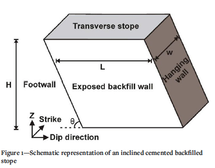
The numerical modelling was performed in FLAC3D, which computes using the finite difference numerical modelling method. Various parameters such as height (H), width (w), and length (L) of the backfill column, the inclination of the orebody (Θ), and the ratio of interface cohesion to the cohesion of backfill material (rc) were varied in the modelling. The stability of the system was studied using Mohr-Coulomb elastoplastic analysis. During the study, various models corresponding to a hard rock mining scenario were simulated. A transverse stoping configuration was modelled, as shown in Figure 1. Although when L<w, the stope dimension corresponds to that of a longitudinal stope, the nomenclature followed in this paper is consistent with that of a transverse stope. The dimensions of the stopes considered in the models are H = 25 m, 35 m, 60 m, 75 m, and 100 m, L = 10 m, 30 m, 46 m, 60 m, and 80 m, w = 10 m, 20 m, 30 m, 40 m, and 50 m, and Θ = 45°, 60°, 75°, and 90°. Those combinations commonly practised in the real mining scenario are simulated for the study.
Separate finite difference grids were created for each orebody dip. The grid starts from the surface and extends to a depth of about 600 m. The boundaries were kept a sufficient distance (more than 150 m) from the stoping region. A vertical plane of symmetry was applied passing through the centre of the secondary stope. Extraction of the secondary stope results in exposure of the primary stope paste-fill wall. Moderate in-situ stress values were applied; those measured in Indian hard rock mines (Gowd , Rao, and Gaur, 1992). A 'fair' rock mass rating (RMR between 40 and 60) was used in all the models. The pertinent rock mass properties used include a Young's modulus of 25 GPa, Poisson's ratio of 0.25, cohesion 5.0 MPa, friction angle 35°, and tensile strength 2.0 MPa. These are the typical values found in Indian hard rock mines. During modelling the interface between the rock mass and the fill material was simulated along the footwall, hangingwall, stope bottom, and the wall contact of the adjacent stope. The cohesion ratio (rc) was varied between 0.25 and 1.0, and the tensile strength of the interface was considered to be zero. Tight filling of the stope is complicated in practice, hence in the simulations, a gap of 1 m is provided between the fill top and the stope back.
The backfill properties assigned during the numerical modelling were devised partly based on previous laboratory testing and partly from the literature. The laboratory testing divulged that the friction angle does not vary significantly with changes in the UCS, cohesion, and Young's modulus. Terzaghi (1943) postulated that the angle of internal friction of the paste fill and the rock-fill interface friction angle might be considered equal, while Marston (1930) suggested that the interface friction angle varies from 1/3 to 2/3 times the internal friction angle of the paste fill material. Some researchers have suggested that the interface friction angle can be greater than 2/3 of the friction angle of the paste fill material (Nasir and Fall, 2008; Fall and Nasir, 2010). In the current study, the friction angle at the interface is taken as 2/3 of the internal friction angle of the backfill material for all simulations.
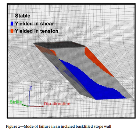
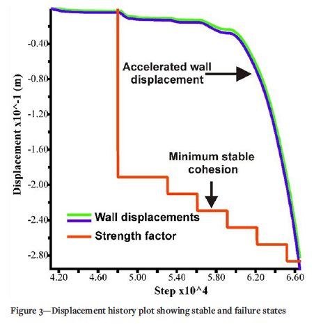
Once the backfill wall is exposed, its stability is very similar to that of a slope stability problem. The Mohr-Coulomb model has been widely used for solving such problems, as it is more simplified, and predicts the stability with reasonable accuracy. The strength reduction technique is a standard procedure used for arriving at a safety factor for a highwall or a slope. A similar approach is followed here to estimate the limiting strength values of the backfill wall material. Failure of the backfill system can be observed from accelerated backfill wall displacement along with the formation of a large yield zone at the bottom portion of the backfill column. Various researchers have successfully used a similar strategy (Yang and Li, 2017; Liu et al., 2018; Porathur et al., 2018). The cohesion and tension of the backfill material are reduced in steps, and the model is equilibrated after each strength reduction step. The friction angle of the backfill is kept constant as it does not vary much with the other strength parameters. For vertical orebodies (Θ = 90°), instability of the system is identified by a steep increase in the displacement history graph and the wedge-shaped failure formed in the backfill column at an angle approximately equal to the critical angle (a), with subtle curvilinear trajectory. According to the Mohr-Coulomb theory, a = 45° + φ/2, where a is the critical angle of the critical plane with the horizontal and φ is the angle of internal friction of the backfill material. When the orebody is inclined, the failure path can be seen originating at the footwall contact and the floor of the fill column. In contrast, the hangingwall contact portion remains more or less unyielded except for some tensile separation at the interface. Hence, from the numerical modelling results, it may be said that the concept of the critical plane may not apply to inclined orebodies. This can be seen just before the time of wall failure, as shown in Figure 2. Figure 3 shows the displacement history plots during strength reduction - accelerated vertical displacements indicate failure of the backfill wall. The minimum cohesion value resulting in a stabilizing displacement is taken as the 'minimum stable cohesion', which may be considered as the 'required cohesion'. Various such models are simulated with several combinations of the stoping parameters. The effect of each stoping parameter on the wall stability is analysed.
Effects of fill wall height
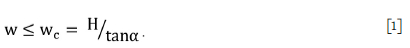
Prior to the 1980s, the UCS requirement of a backfill material at a certain depth was determined theoretically based on the weight of the material (Mitchell, Olsen, and Smith, 1982; Liu et al., 2018). Based on the equation proposed by Mitchell, Olsen, and Smith (1982) and the modified equation by Li (2014), the required cohesion was found to be directly proportional to the height of the backfill column for a free-standing backfill wall. The effect of the height of the backfill column is studied in the numerical modelling by varying the height from 25 m to 100 m for various stope widths, lengths, and dip angles. Figure 4 shows the effect of fill height on the minimum stable cohesion for various stope widths. With increasing height of the backfill column, the minimum required cohesion increases steeply. The trend is in accordance with the theoretical equation of Mitchell, Olsen, and Smith (1982) and Caceres Doerner (2005). Mitchell, Olsen, and Smith's (1982) equation was proposed for stopes of lower widths as compared to height, and hence for higher w/H ratios; the equation is used here by applying a critical width (wc) restriction
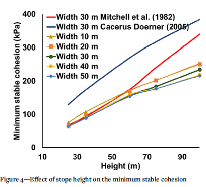
The equation proposed by Mitchell, Olsen, and Smith (1982) agrees with the numerical modelling results for lower stope heights. As anticipated, both the theoretical equations overestimate the required cohesion as they neglect the interface friction, cohesive bonding at the interstope wall, and make other simplifications.
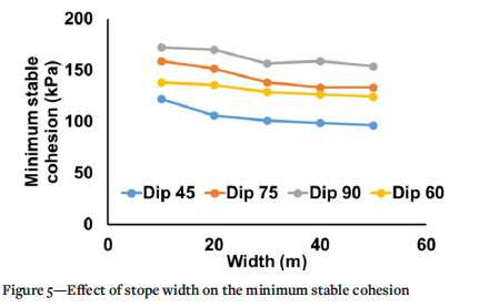
Effect of stope width
In transverse stoping, the width is the lateral extension of the stope along the strike (Figure 1). The effect of stope width is studied by simulating the models for various stope widths (10 m, 20 m, 30 m, 40 m, and 50 m) for various heights, lengths, and dip angles. From the studies, it is clear that the width does not have a significant impact on the stability of the backfill wall. The graph (Figure 5) shows a slightly decreasing trend of the required cohesion as the stope width increases, tending to flatten at large stope widths.
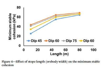
Effect of stope length
Based on the study by Li and Aubertin (2009), for narrow orebodies the stress developed in the backfill material is transferred to a considerable extent to the walls. A similar effect can be seen from the numerical modelling results. Figure 6 shows the effect of stope length on the minimum stable cohesion for various orebody inclinations. The required cohesion increases with the stope length, but tends to flatten at higher stope lengths. This trend is concurrent with the theoretical equations of Mitchell, Olsen, and Smith (1982) and Caceres Doerner (2005). From Figure 6, it can be seen that the effect of orebody inclination is more pronounced for smaller stope lengths (narrow orebodies). When the stope length is larger, the central portions of the backfill behave similarly to the case of a vertical stope. When the orebody is narrow, the backfill is held firmly by the footwall and the hangingwall, thus improving overall wall stability.
Effect of orebody dip
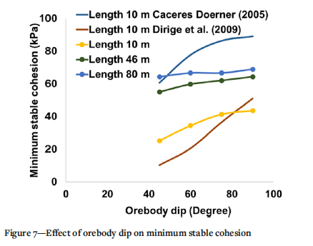
The numerical modelling studies conducted by Li and Aubertin (2009) on stress distribution within the paste fill column revealed that the inclination did not have much influence on the horizontal stresses, while the vertical stress near the hangingwall side reduced significantly for lower orebody inclination (less than 60°). The theoretical equation proposed by Mitchell, Olsen, and Smith (1982) did not incorporate orebody inclination. This equation was later modified by Dirige, McNearny, and Thompson (2009) for inclined stopes by reducing the vertical load acting on the critical plane and transferring it to the footwall contact plane. The theoretical prediction equation for the required UCS proposed by Caceres Doerner (2005) also incorporated orebody dip as a parameter. In the current study, various models with varying orebody dips are simulated. The variation in the minimum stable cohesion with respect to the orebody dip is presented for various stope lengths in Figure 7. It can be seen that the minimum stable cohesion increases in a curvilinear fashion for an increase in orebody dip, with the maximum obtained for the 90° (vertical) scenario. A similar trend can be seen for the earlier theoretical equations of Caceres Doerner (2005) and Dirige, McNearny, and Thompson (2009). However, while the Dirige, McNearny, and Thompson (2009) equation underestimates the required cohesion, the Caceres Doerner (2005) equation overestimates the same, as shown in Figure 7. It may be noted that the Caceres Doerner (2005) equation essentially predicts the required UCS. In our calculation, the required cohesion is evaluated using the Mohr-Coulomb theory
Effect of interface cohesion ratio
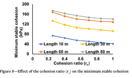
The experimental studies conducted by Koupouli, Belem, and Rivard. (2016) confirmed that the interface cohesion would be 5060% of the backfill cohesion, while on the other hand, parametric studies by Li and Aubertin (2014) concluded that the best results in stress analysis were obtained when the interface cohesion was about 25% of the backfill cohesion. According to Koupouli, Belem, and Rivard (2017), the surface roughness of the contact between rock and backfill impacts the cohesion at the interface, and in some cases the interface cohesion ratio could be as high as 1.0 or even more. In this study, the cohesion ratio (rc) is varied between 0.25 and 1.0. When the ratio of the interface-to-backfill cohesion increases, the minimum stable cohesion decreases, as shown in Figure 8 for various stope lengths. Although the influence of rc on the overall backfill wall stability is not that pronounced, it cannot be neglected. In the absence of data from test work, it will be safer to assume rc = 0.25.
Prediction equation
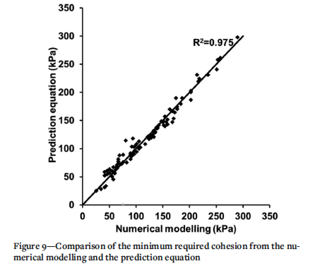
For a field engineer, it will be useful to have a prediction equation to determine the required strength of the backfill based on the stoping parameters. From the numerical modelling exercise, 96 data-sets were created to assess the required cohesion for a stable backfill wall at various heights, widths, lengths, dip angles, and cohesion ratios. Power equations were found to fairly represent the effect of the various parameters involved on the required cohesion. The general form of predictive equation chosen, after several-hit and-miss trials, is
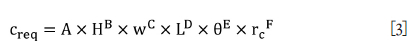
where
creq = required cohesion (kPa)
H = backfill wall height (m)
w = transverse stope width (m)
L = transverse stope length (m)
θ = inclination of the orebody or stope with respect to the horizontal (radian)
rc = ratio of rock-fill interface cohesion to backfill cohesion
A = backfill strength coefficient having units kPa/m(B+C+D)
B, C, D, E and F are exponents.
Using Equation [3], the best-fitting values for the backfill strength coefficient (A) and exponents B, C, D, E and F were obtained using a C++ code employing mean squared error (MSE) minimization and search methods. The combination of values for these constants yielding the minimum MSE is found to be
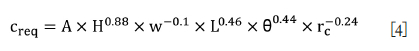
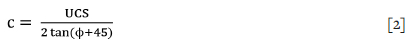
where A = 0.57 kPa/m1.24. The accuracy of the prediction from Equation [4] can be seen from Figure 9. The correlation between the predicted and numerical results has an R2 of 0.975, a mean absolute percentage error of ±7.9%, and an RMSE value of 9.16. The angle of internal friction (f) for cemented backfill samples generally varies between 30° and 40° (Li and Aubertin, 2014; Koupouli et al., 2016; Liu et al., 2017); if not established from laboratory testing, a value in the above range may be assumed. From laboratory testing of the backfill specimen the actual relationship can be drawn between UCS and the cohesion of the backfill at a given site. However, this will require triaxial testing or a direct shear test. In the absence of such a site-specific relationship, the Mohr-Coulomb theory (Equation [2]) may be applied to obtain the required UCS. The design UCS may then be decided based on a factor of safety (FoS).

The FoS in a design should be carefully chosen for each mine site depending on the level of confidence of mine management as regards several other pertinent issues, such as the uncertainty in maintaining backfill mixing ratio, actual strength gain after emplacement in the stopes, effect of blasting-induced vibration, formation of cold joints in the backfill due to unscheduled stoppages, error in the prediction, etc. A FoS of 1.5-2.0 may generally be acceptable in most situations. Applicability of the prediction equation in real cases is limited to the range of stoping parameters considered in this modelling study. If the maximum stope length L (width of the orebody) is less than 10 m, it may
be taken as 10 m in the predictive equation. Theta is the actual inclination of the stope geometry and not necessarily the orebody dip. Hence it should be judiciously used, especially when the stope geometry is altered during mining. The rock mass rating considered in the modelling studies falls in the category 'fair' (RMR 40 and above) (Bieniawski, 1976). For very weak rock mass or under squeezing ground conditions there could be additional stresses acting on the backfill, and the predictive equation (Equation [4]) may not be applicable. A case-to-case numerical modelling study may be performed. Equation [4] is used in a few mining scenarios, as described the case examples. The case examples are not individually modelled. They are presented as application and validation of the developed prediction equation.
Case example 1: Cemented hydraulic fill for a chromite mine
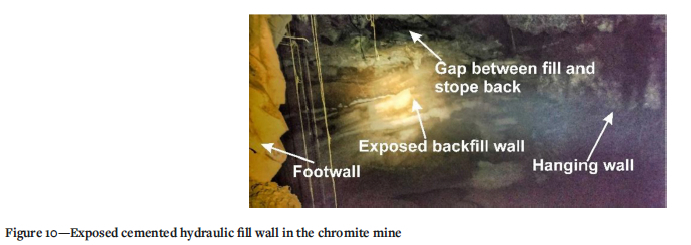
The chromite mine is situated in an ultramafic complex in the eastern part of India. The rock mass is highly jointed and weathered at shallow depth with an RMR of about 40. The orebody is steeply dipping, at 75-84°, and has a width ranging from 6 m to 25 m. The mine employs a blast-hole open stoping method in conjunction with cemented hydraulic fill composed of river sand and ordinary Portland cement (OPC). The mine requires a strong sill to optimize ore recovery from the lower stopes. Hence a plug of about 7.0 m is formed in the first stage of hydraulic filling with higher cement content for greater fill strength. The remaining height of about 43 m is bulk backfill, where the cement percentage needs to be optimized. The applicable stoping parameters for this case example are H = 43 m, w = 18 m, L = 25 m (maximum), θ = 75° and rc = 0.25. The predictive equation (Equation [4]) yields a required cohesion of 79.55 kPa and design cohesion of 119.3 kPa for a FoS of 1.5. The corresponding design UCS is 413.4 kPa. From laboratory tests of hydraulic fill specimens with various cement contents and curing times it was found that with 6% OPC and 28 days of curing the UCS achieved is about 450 kPa, which is sufficient for the backfill wall. The mine has successfully extracted and backfilled over 25 stopes so far in primary-secondary sequence with hydraulic fill containing 6% OPC mixed with river sand in the bulk fill. The plug fill was made in all the stopes with 10% cement content, which had a laboratory tested UCS of 1225 kPa after 28 days of curing. In-situ samples of cured hydraulic fill were also tested after 28 days of emplacement, and showed 373 kPa for the bulk fill and 1096 kPa for the plug fill. The UCS of the in-situ samples was found to be about 10-17% lower than the laboratory prepared samples. Some backfill wall failure was observed initially due to blast vibration, especially when the slot opening was adjacent to the backfill wall. The mine management mitigated this issue by making the slot in the middle of the stope. Figure 10 shows a stable exposed backfill wall during secondary stoping. As considered in the numerical modelling, Figure 10 also demonstrates that a considerable gap between the fill top and the stope back remains after filling.
Case example 2: Cemented rock fill (CRF) for a lead-zinc mine
At this mine site, located in the northern part of India, the Zn-Pb mineralization is hosted in quartzite-mica schist (QMS) in contact with calc-silicate. The orebody is 3-15 m thick with a steep dip (70-90°) at shallow depth, flattering to 0-20°) at greater depth. The mining method is longhole open stoping (LHOS) in longitudinal configuration in the steeper sections and a transverse configuration in the flatter part. Applicable stoping parameters of the steeper part are H = 25 m, w = 25 m, and L = 15 m (maximum), θ = 90° and rc = 0.25; and for the flatter part H = 25 m, w = 15 m, L = 25 m (maximum transverse stope length exposure at a time), θ = 90° (applicable dip of a stope), and rc = 0.25. Due to greater uncertainty in the homogeneity of the CRF mix a design safety factor of 2.0 is recommended. The required cohesion by using the prediction equation is 40.56 kPa for the steeper part of the orebody and 54.27 kPa for the flatter part. The design UCS should then be 348 kPa and 486 kPa for the steeper and flatter parts, respectively. Laboratory testing of 300 mm χ 300 mm χ 300 mm cubical samples of CRF revealed a UCS varying from 485 kPa to 1329 kPa for 5% cement content and 28 days curing, depending on the percentage of fines in the rock fill (10-25 %). The tests also revealed that the maximum strength of the CRF is reached at a fines content of about 15%. However, there are practical difficulties in controlling the percentage of fines during actual filling operations and hence it will be prudent to consider the lowest strength value. The mine currently practices CRF filling in both the steeper and flatter sections with 5% cement content. Apart from occasional minor chipping of the backfill wall during blasting, no major backfill wall failure has been observed so far in the mine.
Case example 3: Paste fill in a lead-zinc mine with a moderately dipping orebody
The lead-zinc mine is situated in the northern part of India and occurs within a Precambrian banded gneiss complex with the host rock mostly comprising graphite-mica-sillimanite gneiss. The orebody dips at an average angle of about 60° and has a width of 10-50 m. The mine uses longhole open stoping (LHOS) in transverse or longitudinal configuration, depending on the orebody width, with a level interval of 25 m. The mine practises underhand as well as overhand mining using paste fill. The applicable stoping parameters for paste fill wall design in overhand stoping are H = 25 m, w = 15 m, L = 50 m, (maximum), θ = 60°, and rc = 0.25. The required cohesion using Equation [4] is 62.6 kPa, which corresponds to the design UCS of 361 kPa for a safety factor of 1.5. A series of laboratory tests conducted using the mill tailings from the mine site mixed with various percentages of OPC as well as pozzolana Portland cement (PPC) was found that a UCS of 360-400 kPa can be achieved with either 6% PPC or 11% OPC. The requirement for underhand stoping will be different, but this is beyond the scope of this paper. The mine currently practises paste filling in overhand mining stopes with 10% OPC, 2% fly ash, and 88% mill tailings, which has a laboratory tested UCS in the range of 360-400 kPa.
Conclusion
The study proved that numerical modelling is a versatile tool compared to simplified theoretical models, which more accurately represents the effect of various stoping parameters on the required backfill strength. The pattern of yielding in a backfill column at the time of failure roughly agrees with the critical plane postulated in the earlier theoretical models (Mitchell, Olsen, and Smith, 1982; Dirige, McNearny, and Thompson, 2009; Liu et al., 2018) for vertical orebodies (θ = 90°), but was found to differ widely for inclined ones (θ < 90°). The theoretical equations generally appear to overestimate the required strength of a backfill material as they ignore some key aspects such as interface friction, cohesive bonding at the inter-stope wall, and the stress arching phenomenon. From the parametric study, it was found that the stope height is the parameter with the most influence in determining the required strength of the backfill, whereas the stope width has the least influence. The stope length (L), stope inclination (θ), and cohesion ratio (rc) have a significant influence on the wall stability for thinner orebodies but are mostly trivial for wider orebodies. The numerical modelling methodology developed by tracking the wall displacement and the plasticity state was very effective for estimating the required strength for a cemented backfill material in a variety of practical underground stoping scenarios. The predictive equation developed based on the numerical modelling results has good accuracy and should be a useful tool for field engineers for calculating the required cohesion and UCS quickly and fix the optimum binder percentage in the backfill mix accordingly.
Acknowledgements
The authors would like to thank the Director of CSIR-Central Institute of Mining and Fuel Research for the permission to publish this work. The help and support offered by the officers of Hindustan Zinc Limited and Indian Metals and Ferro Alloys Limited during field implementation are greatly appreciated. The authors' views are not necessarily of the institute to which they belong.
References
Aubertin, M., Bussière, B., and Bernier, L. 2002. Environnement et gestion des rejets miniers: Manuel sur cédérom. Presses Internationales Polytechnique. [ Links ]
Benzaazoua, M., Bussière, B., Demers, I., Aubertin, M., Fried, E., and Blier, A. 2008. Integrated mine tailings management by combining environmental desulphurization and cemented paste backfill: Application to mine Doyon, Quebec, Canada. Minerals Engineering, vol. 21, no. 4. pp. 330-340. [ Links ]
Bieniawski, Z. 1976. Rock mass classifications in rock engineering. Proceedings of the Symposium on Exploration for Rock Engineering, Johannesburg, South Africa. Balkema, Rotterdam. pp. 97-106. [ Links ]
Brady, B.H.G. and Brown, E.T. 2004. Rock Mechanics for Underground Mining: 3rd edn. doi: 10.1007/978-1-4020-2116-9 [ Links ]
BussiÈRE, B. 2007. Hydrogeotechnical properties of hard rock tailings from metal mines and emerging geoenvironmental disposal approaches. Canadian Geotechnical Journal, vol. 44, no. 9. pp. 1019-1052. [ Links ]
Caceres Doerner, C.A. 2005. Effect of delayed backfill on open stope mining methods. MASc thesis, University of British Columbia. [ Links ]
Darling, P. 2011. SME Mining Engineering Handbook. Society for Mining, Metallurgy & Exploration, Littleton, CO. [ Links ]
Dirige, A.P.E., McNearny, R.L., and Thompson, D.S. 2009 The effect of stope inclination and wall rock roughness on back-fill free face stability. Rock Engineering in Difficult Conditions: Proceedings of the 3rd Canada-US Rock Mechanics Symposium. American Rock Mechanics Association, Alexandria, VA. pp. 9-15. [ Links ]
Duncan, J.M. and Wright, S.G. 2005. Soil Strength and Slope Stability. Wiley, Hoboken, NJ. [ Links ]
Fall, M. and Nasir, O. 2010. Mechanical behaviour of the interface between cemented tailings backfill and retaining structures under shear loads. Geotechnical and Geological Engineering, vol. 28, no. 6. pp. 779-790. [ Links ]
Gowd, T.N., Rao, S.S., and Gaur, V.K. 1992. Tectonic stress field in the Indian subcontinent. Journal of Geophysical Research: Solid Earth, vol. 97, no. B8. pp. 11879-11888. [ Links ]
Hartman, H.L. 1992. SME Mining Engineering Handbook. Society for Mining, Metallurgy & Exploration, Littleton, CO. [ Links ].
Hassani, EP. and Archibald, J.F. 1998. Mine Backfill. CIM, Montreal, Quebec, Canada. [ Links ]
Koupouli, N., Belem, T., and Rivard, P. 2017. Shear strength between cemented paste backfill and natural rock surface replicas. Proceedings of the First International Conference on Underground Mining Technology, Australian Centre for Geomechanics, Perth. Hudyma, M. and Potvin, Y. (eds). pp. 375-385. doi: 10.36487/acg_rep/1710_29_koupouli [ Links ]
Koupouli, N.J., Belem, T., Rivard, P., and Effenguet, H. 2016. Direct shear tests on cemented paste backfill-rock wall and cemented paste backfill-backfill interfaces. Journal of Rock Mechanics and Geotechnical Engineering, vol. 8, no. 4. pp. 472-479. doi: 10.1016/j.jrmge.2016.02.001 [ Links ]
Li, L. 2014. Generalized solution for mining backfill design, International Journal of Geomechanics, vol. 14, no. 3. doi: 10.1061/(ASCE)GM.1943-5622.0000329. [ Links ]
Li, L. and Aubertin, M. 2009. Numerical investigation of the stress state in inclined backfilled stopes. International Journal of Geomechanics, vol. 9, no. 2. pp. 52-62. doi: 10.1061/(asce)1532-3641 [ Links ]
Li, L. and Aubertin, M. 2014. An improved method to assess the required strength of cemented backfill in underground stopes with an open face. International Journal of Mining Science and Technology, vol. 24, no. 4. pp. 549-558. doi: 10.1016/j.ijmst.2014.05.020 [ Links ]
Liu, G., Li, L., Yang, X., and Guo, L. 2017. Numerical analysis of stress distribution in backfilled stopes considering interfaces between the backfill and rock walls, International Journal of Geomechanics, vol. 17, no. 2. doi: 10.1061/(ASCE) GM.1943-5622.0000702 [ Links ]
Liu, G., Li, L., Yang, X., and Guo, L. 2018. Required strength estimation of a cemented backfill with the front wall exposed and back wall pressured, International Journal of Mining and Mineral Engineering, vol. 9, no. 1. pp. 1-20. doi: 10.1504/IJMME.2018.091214 [ Links ]
Marston, A. 1930. The theory of external loads on closed conduits in the light of the latest experiments. Bulletin 96, Iowa Engineering Experiment Station, Iowa State College, Ames, IA. [ Links ]
Mitchell, R.J., Olsen, R.S., and Smith, J.D. 1982. Model studies on cemented tailings used in mine backfill. Canadian Geotechnical Journal, vol. 19, no. 1. pp. 14-28. doi: 10.1139/t82-002 [ Links ]
Nasir, O. and Fall, M. 2008. Shear behaviour of cemented pastefill-rock interfaces, Engineering Geology, vol. 101, no. 3-4. pp. 146-153. [ Links ]
Porathur, J. L., Jose, M., Bhattacharjee, R., and Tewari, S. 2018. Numerical modeling approach for design of water-retaining dams in underground hard rock mines-A case example. Arabian Journal of Geosciences, vol. 11, no. 23. p. 750. [ Links ]
Potvin, Y., Grant, D., and Mungur, G. 2015. Towards a practical stope reconciliation process in large-scale bulk underground stoping operations, Olympic Dam, South Australia. CIM Journal, vol. 6, no. 2. pp. 102-110. [ Links ]
Simms, P., Grabinsky, M., and Zhan, G. 2007. Modelling evaporation of paste tailings from the Bulyanhulu mine. Canadian Geotechnical Journal, vo;. 44, no. 12., pp. 1417-1432. [ Links ]
Terzaghi, K. 1943. Bearing capacity. Theoretical Soil Mechanics. Wiley, New York. pp. 118-143. [ Links ]
Yang, P. and Li, L. 2017. Numerical and limit equilibrium stability analyses of cemented mine backfill upon vertical exposure. UMT 2017: Proceedings of the First International Conference on Underground Mining Technology. Hudyma, M. and Potvin, Y. (eds). Australian Centre for Geomechanics, Perth. pp. 399-408. doi: 10.36487/acg_rep/1710_31_yang [ Links ]
Yang, Z., Zhai, S., Gao, Q., and Li, M. 2015. Stability analysis of large-scale stope using stage subsequent filling mining method in Sijiaying iron mine. Journal of Rock Mechanics and Geotechnical Engineering, vol. 7, no. 1. pp. 87-94. [ Links ]
Yu, Q., Chen, X., Dai, Z., Nei, L., and Soltanian, M.R. 2018. Numerical investigation of stress distributions in stope backfills. Periodica Polytechnica Civil Engineering, vol. 62, no. 2. pp. 533-538. doi: 10.3311/PPci.11295. [ Links ]
Zhang, J., Zhang, Q., Huang, Y., Liu, J., Zhou, N., and Zan, D. 2011. Strata movement controlling effect of waste and fly ash backfillings in fully mechanized coal mining with backfilling face. Mining Science and Technology (China). vol. 21, no. 5. pp. 721-726. [ Links ]
Zhang, Q., Zhang, J., Guo, S., Gao, R., and Li, W. 2015. Design and application of solid, dense backfill advanced mining technology with two pre-driving entries. International Journal of Mining Science and Technology, vol. 25, no. 1. pp. 127-132. [ Links ] ♦
 Correspondence:
J.L. Porathur
Email: johnlouip@gmail.com
Received: 26 Feb. 2021
Revised: 24 Feb. 2022
Accepted: 22 Mar. 2022
Published: May 2022
ORCID: J.L. Porathur https://orcid.org/0000-0002-1168-7640
S. Sekhar https://orcid.org/0000-0001-9289-4803

