


Services on Demand
Article
 English (pdf)
 Article in xml format
 Article references
Indicators

Related links
-
 Cited by Google
 -
 Similars in Google
Share

 Permalink
Journal of the Southern African Institute of Mining and Metallurgy
On-line version ISSN 2411-9717
Print version ISSN 2225-6253
J. S. Afr. Inst. Min. Metall. vol.119 n.6 Johannesburg Jun. 2019
http://dx.doi.org/10.17159/2411-9717/663/2019
FURNACE TAPPING
Development, installation, and operation of a full-copper, deep-cooled slag tapblock for a six-in-line copper matte settling electric furnace
B.N. BelfordI; P. ConradieI; T. MwanzaII
IMetix (SMS Group), South Africa
IIFirst Quantum Minerals' Kansanshi Mining Plc, Solwezi, Zambia
This paper was first presentedat the Furnace Tapping 2018 Conference, 15–16 October 2018, Nombolo Mdhluli Conference Centre, Kruger National Park, South Africa.
SYNOPSIS
Metix has introduced a three-piece 'deep-cooled' copper slag tapblock into a six in-line copper matte settling electric furnace. The tapblock was designed without any internal refractory; it relies purely on the development and maintenance of a freeze lining on its hot face and within the tapping channel to protect the copper and promote the integrity of the surrounding endwall refractory lining. In addition, the geometry of the tapblock further supports the sidewall refractories, reduces the impact of funnelling and, therefore, the need for premature rebuilding of the furnace endwall, and facilitates easy removal and replacement of the wear components even under 'hot' furnace conditions. Eighteen thermocouples embedded in the copper components ensure full resolution of the copper condition, enabling plant personnel to identify wear rates, estimate freeze lining thickness and stability, and schedule replacement of spares and wear components well in advance.
At the time of writing the tapblock had been in operation for 6 months with approximately 350 000 t of slag having been tapped through it. Every indication is that the design will limit the need for premature relining of the furnace endwall due to rapid deterioration of the tapblock and its surrounding refractories.
Keywords: hot repair, slag, tap-hole, tapblock, refractory, condition monitoring.
Introduction
Nonferrous furnaces rely heavily on the maximization of refractory campaign life to increase profitability and reduce planned downtime. In large electric copper slag-cleaning furnaces utilizing insulating linings, campaign lives of six or more years are realistic if consideration is given to each aspect that can degrade the refractory lining during the campaign. An area that is particularly vulnerable is the slag tap-hole and the local surrounding refractory. To avoid premature relining of the furnace walls, every effort should be made to consider not only the tap-hole design itself, but also the selection of the sidewall refractory material and its construction immediately adjacent to the tap-hole, and furthermore the interplay between the tapblock and this adjacent refractory. A holistic approach to the design that considers these interdependent features in the slag tapping area can reduce the incidence of accelerated refractory wear ('funnelling'), support the surrounding refractories to prevent their collapse, introduce easily replaceable wear components that can be exchanged with the furnace still 'hot', and encourage and maintain a stable freeze lining at the refractory hot face that maximizes the tapblock and refractory lifetime.
With the above in mind, this paper will discuss the development of a copper tapblock for operation in a copper matte settling electric furnace (MSEF) over the full development life-cycle, with the aim to prove the viability of the tapblock based on real operational data collected over the period of its operation.
Background
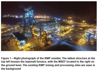
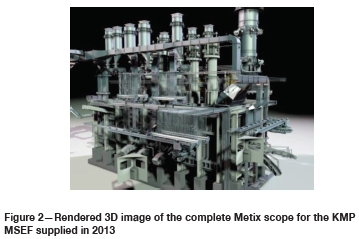
Metix (SMS Group) supplied a 24 MVA rectangular MSEF to First Quantum Minerals (FQM) Kansanshi Mining plc (KMP) for construction of their smelter in 2013/2014 (Chikashi et at., 2016) (Figure 1). The furnace internal dimensions are 24.5 m length χ 7.6 m width χ 5.45 m height. It uses three 8 MVA single-phase transformers to provide power to six 1.2 m Söderberg electrodes employing Metix upper and lower electrode technology. Principal feed to the furnace is through the sidewall from an Isasmelt furnace which receives dry concentrate at a rate of 161 t/h with a turn-up to 200 t/h. Ten charging bins and their associated vibratory feeders and slide gates introduce a mixture of coke and limestone into the furnace. Two additional launders through the furnace endwall allow for the reintroduction of Peirce-Smith converter (PSC) slag to the furnace as well (Figure 2).
The furnace employs an insulating sidewall lining of fused magnesia-chromite bricks, 400 mm thick, separated from a water-cooled sidewall panel by a 50 mm thick conductive ramming layer. The working lining and sub-hearth employ magnesia-chromite (unfused) bricks arranged as an inverted arch and butting up against skewback bricks against the sidewalls. The hearth is cooled by means of ducted cooling air supplied by 14 axial fans along the length of a grillage beam assembly. The furnace roof utilizes a suspended refractory brick system supported by a network of carrier beams off the nine furnace frames that house the shell and limit its transverse expansion. Unlike the sidewalls, the endwalls are restrained by a tie-rod and cup spring arrangement that offers controlled compression of the working lining and sidewall refractories while still allowing for the unavoidable expansion over the length of the furnace.
The MSEF is provided with the following feed (approximate quantities):
> Matte from Isasmelt 1 830 t/d
> Slag from Isasmelt 3 100 t/d
> Return slag from PSC 700 t/d
> Metallurgical coke 22 t/d
> Limestone 25 t/d
With the above as inputs, the approximate output from the MSEF is:
> Matte (74% CuS, 21% FeS, and 3.5% Fe3O4) 1 885 t/d
> Slag (0.7% Cu) 3 745 t/d
Eight matte tap-holes are arranged along the furnace sidewalls; three on the northern wall and five on the southern wall. Matte is tapped into 50 t matte ladles resting on ladle transfer cars and hauled by winch and rail into the converter aisle for handling by 100 t overhead cranes. Two slag tap-holes are installed on the western endwall opposite the Isasmelt and PSC launders which feed the furnace on the east. Slag is tapped via forged copper launders into 50 t slag ladles and transported by Kress hauler to a remote slag dump. The slag tap-holes are opened and closed during tapping campaigns over the course of a day. Tapping campaigns may last several hours, during which time the tap-holes are opened and closed every 15 to 30 minutes as the slag ladles become full and require removal and replacement. On average, each of the two tap-holes is 'tapped' between 35 and 45 times on a given day, with approximately 1 870 t/d slag passing through each tap-hole. Over a year, this equates to approximately 680 000 t slag per tap-hole.
Existing tap-hole design and associated challenges
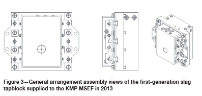
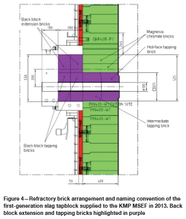
Metix supplied a first-generation slag tapblock (Figure 3) to the KMP MSEF as part of the original engineering, procurement, and supply contract in 2013. This slag tapblock was a two-part, shallow-cooled assembly employing a full copper hot-forged front block and rear hot-forged window block with internal fused magnesia-chromite refractory called the back block extension and tapping bricks, highlighted in Figure 4. The design was unique in that it allowed for the rotation of the front block to change the height of the tapping channel by 200 mm should the operation demand it.
After 18 months of operation, during a routine inspection it was found that the hot-face end of the tapping channel had enlarged significantly with a typical bell-mouth appearance. An internal investigation of the tapblock (with the furnace still hot) showed that the internal tapping bricks in the back block had deteriorated appreciably. Wear on the upper extension brick in the rear block, as shown in Figures 5 and 6, was evidence that the bell-mouth wear profile was large enough to start eroding the base of this brick some 400 mm from the hot face and about 200 mm above the tapping channel centreline.
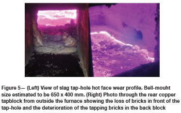
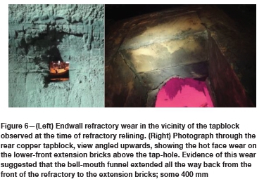
The bell-mouth hot-face opening was estimated to be 650 mm high and 400 mm wide. The hot-face tapping bricks and the endwall bricks surrounding the tapping channel had been largely lost to wear (Figure 6), and a concern developed that the rows of refractory bricks above the tap-hole would start to collapse as the support beneath them was lost. The original design had not employed a lintel block above the tap-hole.
Given the shallow nature of the copper tapblock and the loss of the supporting refractories immediately in front of it, the operations team was unable to replace the hot-face tapping bricks and arrest the 'funnelling' of the surrounding refractory. Owing to the design, only the back block tapping bricks could be replaced
The accelerated wear around the slag tapping channel was not anticipated and was unwelcome given that the targeted campaign life for the first refractory lining was at least four years. After detection of the wear problem, the KMP operations team performed ongoing measurements of the residual refractory lining thickness and a sidewall and endwall relining was planned for 30 months into the furnace's first campaign. In comparison, the copper components of the tapblock were found to be in very good condition at the 18-month (and subsequent) inspections.
Improved slag tapblock design
The design mandate
Upon discovery of the accelerated wear of the refractories surrounding the existing tapblock, a project was initiated to consider design changes that would achieve improvements on several fronts. These included:
> Designing the tapblock such that refractories above the tapping channel were fully supported by the block without the need for a lintel
> Eliminating refractory from the copper blocks
> Instituting 'deeper' copper cooling to achieve a freeze lining at the hot face to reduce, or preferably neutralize, funnelling
> Incorporating re-usable thermowells that could house conventional thermocouples for condition monitoring of the copper
> Enabling hot repair of the tapblock by designing the wear components to be replaceable within 12 hours
> Ensuring that any 'permanent' components of the tapblock employed redundant cooling, i.e. two cooling channels with the possibility to isolate one channel in the event of damage and continue to run on the standby channel.
Design considerations and final design
Metix carried out a project on behalf of KMP to investigate the incorporation of the improvements listed in the previous section in a new slag tapblock for the MSEF. At the outset of the investigation, several constraints were identified.
The new tapblocks were replacing the existing two, and there was little incentive to modify the steel water-cooled endwall to accommodate the new design. The shell endwall comprises closed-circuit serpentine cooling which, if modified during a shutdown, presents challenges and risks. The request was to try to accommodate the existing opening size and means of attachment to the shell endwall with the new design.
The existing block incorporated only two cooling circuits with a flow rate of 15 m3/h to each circuit. The new block was envisaged to have three copper parts, with one of the parts employing a redundant (standby) circuit. This would mean at least two additional circuits per tap-hole (four in total) and an additional water supply of 30 m3/h per tapblock.
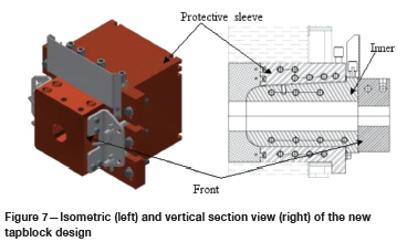
The final tapblock design incorporated three copper parts; the inner block, the protective sleeve, and the front block. The assembly of the three blocks is shown in Figure 7.
The final design fulfilled the design intent as follows:
> Self-support of refractories above the tapblock
As shown in Figure 7, the final tapblock design featured three major copper assemblies; the inner block (a wear part), the protective sleeve (a semi-permanent part designed to last the life of the refractory campaign), and the front block (the outermost block, comparable to a 'mickey/monkey' block in other designs).
The protective sleeve formed the outermost copper assembly and was designed with the express intent of surviving the refractory campaign, the target for which was six years. To do so, the hot face was retracted behind the face of the inner block; the intent being to protect it with a freeze lining after the deterioration of the refractory immediately in front of and surrounding the block.
The rectilinear shape of the protective sleeve and the secure method of attachment to the steel shell guarantee that the protective sleeve can support the above and adjacent refractories of the sidewall. This feature ensures that regardless of refractory wear, a collapse of sidewall refractories in the vicinity of the tapblock is unlikely.
> Elimination of refractory from the copper blocks Extensive computational flow and heat transfer calculations were undertaken to design a tapping channel that was matched with adequate cooling to achieve a stable freeze lining in the channel (a thorough description of the tapblock modelling is discussed in the next section).
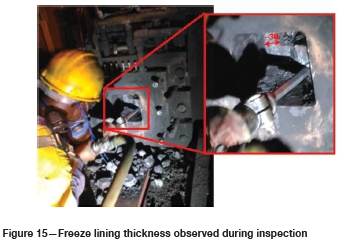
The thermal modelling predicted a tapping channel freeze lining thickness of between 30 and 50 mm, which was well supported by on-site measurements after four months in operation (refer to Figure 15). With the ability to ensure a stable freeze lining, the refractory could be removed from the tapping channel because adequate protection of the copper, as well as thermal insulation, was provided by the frozen slag.
> Deeper cooling to neutralizefunnelling
The original tapblock protruded only 50 mm past the inner face of the shell, i.e. only into the conductive ramming layer behind the 400 mm thick mag-chrome refractory bricks. The new tapblock was considerably deeper, with the protective sleeve terminating 180 mm from the front of the bricks (270 mm from the sidewall inner face) and the inner block terminating 100 mm from the front of the bricks (350 mm from the endwall inner face)
The front or 'hot face' of the protective sleeve was designed to work in conjunction with the inner block to form and support a freeze lining in close proximity to the molten bath.
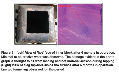
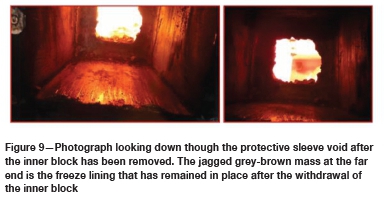
Figure 7 shows that the inner block projects 80 mm beyond the front of the protective sleeve. In addition, the protective sleeve employs dovetails in its front face that serve to bind it to the solidified material layer immediately in front of it. The projection of the inner block was designed to form a shelf to support the freeze lining. The cooling intensity of both the protective sleeve and the inner block is adequate to freeze the copper slag and to increase the thickness thereof to a point where it shrouds both the front of the protective sleeve and the 'bullnose' profile of the projecting inner block. Following an incident of suspected lancing damage, inspections carried out six months after the slag tapblocks went in to operation indicated an acceptable level of funnelling for the period (refer Figure 8). Evidence that funnelling is limited or neutralized over the full campaign life will be possible to obtain only after inspecting the tap-holes after three years. Inspection at the same six-month inspection interval showed little to no wear on the front of the inner block (Figure 8). Photographs taken from outside the furnace (Figure 9) show the freeze lining mass clearly when the inner block is removed. Both findings confirm that the freeze lining is stable (i.e. not eroded away during tapping) and somewhat permanent.
Enabling 'hot repair' of the tapblock
As mentioned before, after six months of operation the inner slag tapblock was removed for inspection following an incident of suspected lancing damage. The inner block was removed with the furnace still hot by undertaking the following steps.
- The furnace was tapped to ensure that the liquid slag level was well below the slag tap-hole level
- Power to the furnace was turned off
- The castable material and splash plates adjacent to the tap-hole were removed
- The thermoelements were removed from the front and inner blocks
- The front block was removed with conventional rigging
- Use jacking locations on the inner block, fasteners were inserted and tightened to eject the inner block
- A purpose-built trolley on a crawl beam was attached to the front of the inner block and supported the weight of the inner block as the trolley was pulled backwards to remove it
- To reinstall the inner block the process was reversed
- The protective sleeve was not changed.
The above removal and reinstallation process of the inner block took less than the allocated 12 hours.
Redundant cooling on permanent components
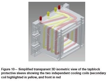
A feature of major importance was the adoption of redundancy on the 'permanent' components of the tapblock. As indicated in Figure 7, the protective sleeve was deemed to be a semi-permanent feature of the tapblock with the intent that it survives at least the targeted six-year campaign life. Given the protective sleeve's role in supporting adjacent refractories, removal and replacement of this component would require access into the furnace. To reduce the likelihood of needing to replace this block, two cooling coils of Monel 400 construction were adopted within the copper body forming the protective sleeve (refer Figure 10). Each cooling coil was designed with its own water inlet and outlet and a dedicated circuit to supply 15 m3/h per coil during normal operation
In the event of damage to the protective sleeve to the extent that the frontmost cooling coil is compromised (highlighted red in Figure 10), this circuit can be isolated and the secondary coil (highlighted yellow in Figure 10) can continue to fulfil the cooling needs of the protective sleeve. Even with only a single coil in operation, the copper protective sleeve is designed to be adequately cooled such that replacement during the refractory campaign period is not required. At the time of writing, no noticeable damage had yet been inflicted on the protective sleeve.
Computational flow and heat transfer modelling
The 'Holy Grail' of thermo-flow modelling of a slag system would ideally be a fully defined set of all temperature-dependent material properties across the entire operating range, i.e. from solidified slag, through the transitionary 'mushy' phase, into superheated liquid. This will remain daunting for designers for two main reasons.
> Firstly, the experimental determination of the transitionary and superheated liquid material properties at temperatures exceeding 1000°C is difficult.
> Secondly, the transitionary phase exhibits nonlinear behaviour, as the slag constituents with higher solidus thresholds freeze preferentially.
Analytical tools like FactSage, based on very large databases of empirical data, are invaluable in the pursuit of this ideal, but hinge on the accuracy of the simulated models, the information in the database, and the accuracy of the slag composition information as supplied by the user.
Even for copper slag systems, where the macro-behaviour and chemistry are well understood, reported values for specific properties of frozen slags, such as thermal conductivity, can vary by up to 400% (Nelson and Hundermark, 2014), making accurate dynamic modelling of a slag tap-hole and freeze lining system a challenge, especially as part of an accelerated product development cycle. In a tapblock, the thermal conductivity of the frozen slag lining can be up to 150 times less than that of the copper block. Therefore, the freeze lining thickness will be the single most influential factor ('throttle') in the energy balance of the tapblock. Despite this uncertainty in absolute properties, the consensus is that a frozen slag lining is achieved reasonably easily, and once established, remains stable and robust (Nelson and Hundermark, 2014) provided that no significant external influence, for example oxygen lancing, results in a disruption of the freeze lining.
If experimentation, analytical modelling, and sensitivity analyses are utilized, temperature-dependent material property accuracies of between 10 and 15% can be compiled. However, this exercise would be time-consuming, especially in the absence of tools like FactSage, making it unfeasible in the context of a product development cycle shorter than three months. For the tapblock under discussion in this paper, it was therefore, necessary to devise an alternative thermo-flow modelling methodology and applicable evaluation metrics.
Modelling methodology and set-up
Instead of ascertaining a single, specific freeze lining thickness using temperature-dependent material properties, a methodology was adopted whereby a series of known freeze lining geometries was imposed on the model and the resultant thermal gradients were analysed to determine a range of anticipated steady-state thicknesses.
The modelling approach was therefore reduced to the following steps.
> Select an operating cooling water flow rate
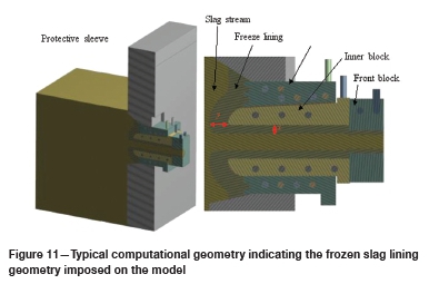
> Prepare geometry of x mm/y mm freeze lining thickness (refer to Figure 11)
> Complete a hydrostatically driven CFD thermo-flow model for a given cooling water flow rate and slag temperature
> Establish whether the liquidus isotherm is positioned in the freeze lining or in the slag:
o If the isotherm is in the freeze lining and close to the surface of the freeze lining, it represents the upper operating thickness of the freeze lining, i.e. the thickest it will be for the given operating conditions
o If the isotherm is in the slag and close to the slag-freeze lining interface, it represents the lower operating thickness of the freeze lining, i.e. the thinnest it will be for the given operating conditions
> Repeat steps 2-4 for various freeze lining thicknesses, x and y, until one of the criteria above is met, then:
o Report the outlet water temperature for the respective cooling water circuits for the selected water flow rate
o Probe the copper temperature at known thermocouple positions (refer to Figure 20)
> Restart at step 1 with a new water flow rate.
The modelling methodology is subject to the following core assumptions.
> Properties at the operating temperatures of the respective materials remain near-constant
> The tap-hole diameter through the front tapblock is the same as the diameter of the tap-hole drill
> The furnace level remains constant during the course of each analysis.
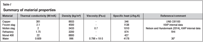
The greater the thermal conductivity of the liquid and frozen slag, the deeper the cooling will penetrate and thus the thicker the freeze lining that will form. A degree of conservatism in the prediction of the freeze lining stability can, therefore, be introduced by assuming the lower thermal conductivity from the range reported in the literature. The full list of material properties used in the design is summarized in Table I.
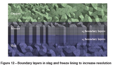
Even though the slag flow is laminar, the aforementioned methodology requires sufficient resolution on either side of the slag-freeze lining interface. To this end, 15 one-millimetre 'boundary layers' (or 'inflation layers') were defined in both the slag and freeze lining, as shown in Figure 12. In addition, the water circuits were meshed with the requisite number of boundary layers for the realizable k-ε turbulence model. As the cooling water coils for the inner block and protective sleeve feature smooth bends and the micro-level flow behaviour is not of specific interest, the necessity to capture recirculation zones and vortices by explicitly solving the viscous sublayer, as would be prevalent with mitre bends or abrupt contractions or expansions, is diminished, which meant the mesh size and solution time could be reduced by opting for the k-ε two-equation model. The k-ε model was combined with the 'Enhanced Wall Treatment' function to make the solution y+-independent by mitigating any inaccuracies at lower y+ values that arise when using the Standard Wall Function (ANSYS, 2017).
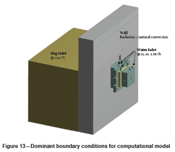
The physical complexity of the problem was reduced by including only dominant boundary conditions, as summarized in Figure 13. Since the problem is driven by the hydrostatic pressure of the liquid slag, the inlet of the slag is simply defined as a pressure boundary, at the specified level, that allows slag to enter the domain at 1250°C. Water through the respective cooling circuits is defined as a mass flow inlet correlated to a volumetric flow rate between 15 m3/h and 5 m3/h in order to gauge the system sensitivity to water flow rate, and to evaluate the lower limit of the water flow rate that ensures the safe operation of the equipment. Given the surface area of the furnace wall, the energy dissipated through radiation to the atmosphere and natural convection was deemed noteworthy in the larger energy balance, specifically in the area where the freeze lining was expected to be in direct contact with the wall refractory. The remainder of the exposed surfaces, like those of the copper components, were assumed to not dissipate any significant amount of energy, and were therefore adiabatic in the context of this investigation.
Results and interpretation
Based on a laboratory analysis of the KMP copper slag, accurate temperature bands were ascertained for the solidus and liquidus temperatures. Since discrete values for each were required in the determination of the freeze lining thickness, the liquidus and solidus temperatures were chosen to be 1160°C and 1059°C respectively for the tapblock design. For the purpose of this qualitative investigation, it was assumed that the slag freeze lining would extend to the liquidus isotherm.
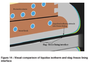
Using the liquidus isotherm as an indicator of the freeze lining extent, it is possible to visually establish how close to convergence the iterative geometry methodology is. Figure 14 shows the liquidus isotherm inside the freeze lining, but not sufficiently close to the slag-freeze lining interface, suggesting that this freeze lining is still 'too thick'. Similarly, the liquidus isotherm would appear in the slag if the freeze lining was 'too thin'. While the objective was to get the liquidus isotherm and interface to match exactly, a variance of approximately 1 mm was deemed reasonable to proclaim a converged cycle.
For the given water flow rates of 15 m3/h (design flow rate), 10 m3/h, and 5 m3/h, it was established that the freeze lining would vary between 28 and 30 mm in thickness. Due to the inner block resting directly on the protective sleeve, as opposed to being grouted in place as with the other three sides, the freeze lining was predicted to be slightly thicker along the bottom of the tap-hole channel.
While condition monitoring and maintenance observations will be discussed in detail in the following sections, it is rewarding to note that the freeze lining thickness of approximately 30 mm observed during inspection of the inner block, as shown in Figure 15, aligns well with the predicted values. This confirms the insensitivity of the freeze lining to changing operating conditions, and for that reason, validates the 'operating envelope' approach as a simplified method to predict slag tap-hole performance.
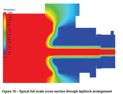
A typical cross-section through the modelled tapblock (Figure 16) illustrates the thermal gradients throughout the computational domain. It is promising that for this example, all the copper operates below 150°C, which is the conservative accepted softening temperature for non-alloyed copper. Even though these components should not typically be externally stressed, the protective sleeve plays a vital role in the refractory sidewall integrity and could, therefore, be considered a structural component. It is standard practice within Metix to remain below this temperature threshold for 'structural' copper components.
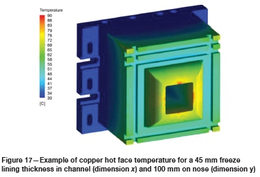
The copper temperature plot shown in Figure 17 is a useful tool for visualizing the heat load distribution on the copper hot face. The combination of a contraction in flow at the tap-hole inlet, the round tapping channel geometry in a square opening, and the distance to the nearest water channel all contribute to the hot face of the inner block being thermally taxed compared to the rest of the tap-hole assembly. In this application, a compromise will be required between cooling channel proximity to the hot face and sufficient copper thickness to act as a physical and thermal protective buffer in a deep-cooled component.
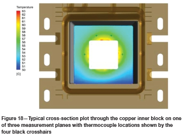
Over and above proving the thermal viability of the tapblock, a secondary purpose of the modelling was to determine the copper temperature at discrete locations in the copper components. The final tapblock solution installed at KMP featured 18 thermocouples (four in the protective sleeve, twelve in the inner block, and two in the front block) positioned at key locations to provide a condition monitoring functionality that is described later in this paper. A typical cross-section through one of the measurement planes, shown in Figure 18, indicates the locations of the monitoring points of the inner block by means of four crosshairs.
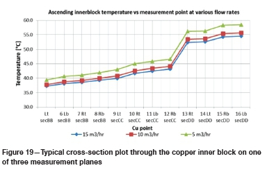
Plotting the temperatures at each of the 12 measurement points in the inner block for each converged freeze lining thickness cycle not only gives a useful visual indication of what the temperature monitoring alarms could be set to during physical operation, but also allows a quick comparison of the impact of varying cooling water flow rates. Figure 19 plots the copper temperatures for a given freeze lining geometry for three discrete cooling water flow rates. From this it is reasonable to conclude that once the freeze lining is established, it requires very little cooling to maintain, and manipulating the cooling water flow would be an ineffective means to manipulate the freeze lining thickness, and subsequently the slag tapping rates.
The ability to create and maintain a freeze lining in a tapblock offers the designer a margin of forgiveness, especially in applications where the slag superheat is limited; less than 90°C in the KMP MSEF operation. As predicted, the freeze lining does indeed act as the dominant factor in the energy balance of the tapblock and renders the system balance somewhat insensitive to changes in the slag and cooling water flow rates. Nonetheless, this development modelling was grounded on a series of simplifications and assumptions that, although valid, render the results an equal blend of qualitative and quantitative findings, with the single most important outcome being the added understanding of the performance response of this novel tapblock design in this application.
Condition monitoring
Methods employed
The new tapblock supplied by Metix to KMP is essentially a 'deep-cooled tapblock', meaning that cooling water is introduced into the endwall refractory region together with the equipment. This design, while proven in industry, must be respected for the associated dangers introduced by cooling water in close proximity to a molten bath.
To perform condition monitoring, three monitoring techniques were used, namely cooling water flow rate (in m3/h), cooling water temperatures (both inlet temperature and ΔΤ in degrees Celsius), and copper temperature (in degrees Celsius). The first two techniques are common on most water-cooled furnace elements and will not be described further here. To measure the copper temperature, conventional thermocouples were used. The various measured variables were displayed in real time on the supervisory control and data acquisition (SCADA) system and saved to the operational database for daily trending and interpretation.
Layout of the condition monitoring elements
These thermocouples were arranged as follows:
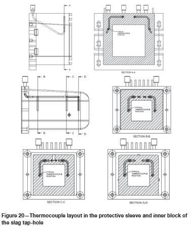
> Four measuring locations on the hot face of the protective sleeve, as shown by section A-A in Figure 20
> Twelve measuring locations across three planes in the inner block, as shown by sections B-B, C-C, and D-D in Figure 20. Four measurement points were present on each of the three planes
> Two measurement locations beneath the tapping channel in the front block (not shown).
To allow the thermoelements to reach the desired measurement locations, a blind conduit of stainless steel was precast into the copper body. Thermoelements of known lengths and 1.5 mm in diameter were fed into the conduits during installation so as to reach the prescribed measurement points. The CFD analysis that was undertaken was used as a tool to estimate the copper temperatures at the different measurement locations and to provide KMP with the expected operating ranges, as well as values for alarm set-points for the copper temperature.
Data collection and interpretation
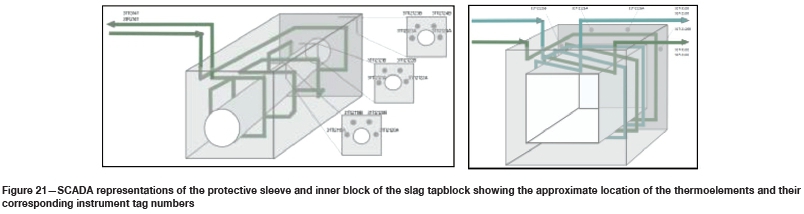
The data collected by the slag tapblock thermocouples, as well as the cooling flow meters and thermocouples, was displayed on the SCADA alongside graphics that represented the protective sleeve and inner block components (refer Figure 21). The alarm limits were programmed into the SCADA to alert the operator to unusual operation.
The condition monitoring variables were exported daily to an Excel-based analysis tool developed between KMP and Metix. As described in the first section of this paper, each tap-hole may be used up to 45 times in a single day. Each usage cycle would be characterized by drilling (or lancing) the tap-hole open, establishing slag flow until a slag ladle had been filled, and then plugging the tap-hole with the mud gun. Each of these tapping cycles may last between 15 and 30 minutes, during which time a noticeable rise in the copper temperatures and cooling water temperatures would be experienced. Between the tapping cycles, the copper and cooling water temperatures would not be of much relevance as the tap-hole would be closed and deemed to be safeguarded against damage.
The analysis tool was thus complicated by having to discard the data between tapping cycles and process only the data-points between the beginning and end of tapping. To this end, level sensors mounted above the slag ladle bay were used to measure the slag levels in the ladles during operation. By calculating the rate of change of the slag levels measured by the sensors, the beginning of a tap and the end of a tap could be clearly identified, and then the associated variables recorded and interpreted. The other product of these calculations was real-time measurements of the slag flow rates (m3/h) during operation. These results were used to validate earlier design modelling work.
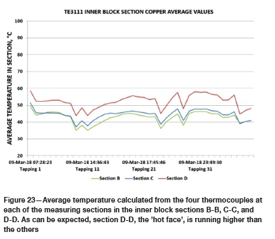
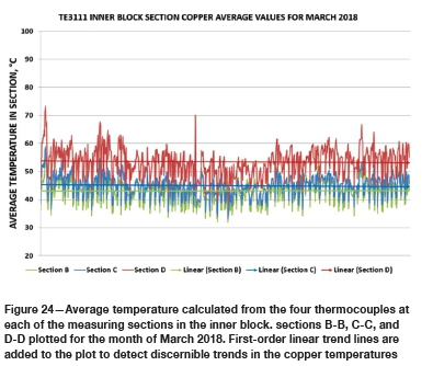
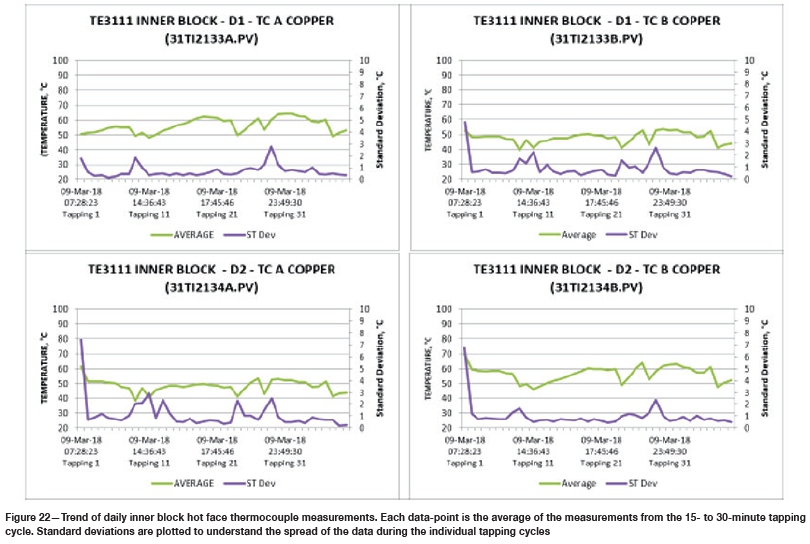
While all the measured variables were important, particular focus was placed on measuring the hot face temperatures on the protective sleeve (section A-A in Figure 20) and the inner block (section D-D in Figure 20). Each of these locations was monitored by four thermocouples. Each individual thermocouple was recorded and graphed (refer Figure 22), as well as the average of the four thermocouples at each location (refer Figure 23). The average daily trends were then plotted over the course of a month to trend any increases in the copper temperatures (refer Figure 24).
Given that up to 50 tapping cycles were recorded per day, each data-point on the individual thermocouple plots (Figure 22) represented the average of the individual thermocouple measurements from the 15- to 30-minute tapping cycle. Standard deviations for each thermocouple during each tapping cycle were plotted to understand the spread of the data during the individual tapping cycle to ensure that temperature spikes were captured.
Usefulness of condition monitoring
Over the course of the first seven months of the tapblock operation the trends in Figures 22 and 23 were produced daily and assessed by both KMP and Metix engineers. These trends enabled hotter tapping cycles and lancing events that led to extreme copper temperatures being identified. One useful interpretation of the graphs was to assess whether the tapblock returned to a normal temperature range after a high-temperature event. It was sometimes seen that the copper ran 20°C hotter than the average during certain tapping cycles. After these higher than usual cycles, the tapblock temperatures were monitored to see if the temperatures reduced, thereby indicating that a freeze lining had re-established, and the tapblock was again operating normally.
The monthly trends, as shown in Figure 24, were used as a tool to try to identify wear of the inner block and the protective sleeve. While an upward trend on the inner block was discernible in the first four weeks of operation, trends beyond this initial 'bedding-in' period were mostly flat. This gave every indication that wear on the inner block and the protective sleeve was not occurring due to an erosive or melting mechanism during tapping.
Conclusions and the way forward
This paper has attempted to describe the background to, and the need for, the design and adoption of a modified slag tapblock for First Quantum Minerals' KMP MSEF. The design mandate for the modified block has been described, together with the operational experience and condition monitoring.
During the first refractory campaign of the MSEF, which lasted only 30 months, the refractories above and immediately adjacent to the slag tapblocks were eroded to the point that refractory collapse was likely if the wall was not relined. With a targeted refractory campaign life of six years, a tapblock capable of limiting the erosive wear and supporting the surrounding refractory was required. KMP employed the services of Metix, the original furnace designer, to investigate the redesign of the slag tapblock to achieve the required campaign life and incorporate other key performance features.
The tapblock was designed to fit within the endwall opening of the existing block. The slag tapblock employed three primary components, namely an outer protective sleeve, an unlined inner block, and a front block to act as a flow restriction device. The protective sleeve was deemed to be a 'permanent' component capable of surviving the full refractory campaign period. The inner and front blocks were considered wear items and were designed to be replaced within 12 hours with the furnace still 'hot'. The protective sleeve acted as an integral lintel and flanker cooler by providing support to the refractories above and to the side of the tapblock. To limit the need for protective sleeve replacement, dual cooling coils were adopted to provide redundancy, i.e. in the event that damage was sustained on the protective sleeve hot face, the frontmost coil could be isolated and the secondary coil would be capable of adequately cooling the block.
Given the erosive damage witnessed on the refractories of the original tapblock, removal of tapping channel refractories was considered a key feature of the new tapblock. Metix employed extensive CFD modelling of the tapblock to characterize the slag flow rate and the tapblock's ability to work without the need for internal refractories. The CFD modelling enabled the designers to determine the required cooling to achieve a predicted slag freeze lining thickness. Based on this modelling, the freeze lining stability could be quantitatively estimated and the modelling results predicted that a stable freeze lining would be achieved together with the geometrical features to support it on the 'hot face'.
After 6 months in operation the tapblock was inspected for performance and wear. The inner block was removed to assess the condition of the 'hot face' and internal visual inspections of the endwall refractory lining were undertaken to determine the degree of 'funnelling'. These early indications were positive, with negligible wear found on the front face of the inner block and acceptable refractory wear observed. Further investigations after longer operating periods will be required to evaluate the longer-term performance of the tapblock.
Condition monitoring of the tapblock was considered a key feature in the conceptual design phase to provide a real-time tool to evaluate the tapblock condition. Given the adoption of deep-cooled copper components, forewarning of damage that may pose a risk to furnace operation and personnel was required. A total of 18 thermocouples were adapted by precasting blind stainless steel conduits into the copper tapblock bodies. The CFD modelling allowed for the theoretical determination of the copper temperatures at the 18 locations. These theoretical temperatures were used to quantify normal and alarm conditions. The data acquired by the thermocouples, together with other basic variables like cooling water flow rates and water temperatures, was displayed in real time on the SCADA and plotted daily in a Microsoft Excel-based analysis tool. The tool allowed abnormal events to be identified, copper component temperature to be monitored on a tap-by-tap basis, and wear to be trended month-to-month.
The inspection carried out after 6 months of operation revealed that the inner block had sustained negligible erosive wear during tapping. There was no evidence to suggest that the protective sleeve had suffered any damage during the period either. A visual inspection of the endwall refractory wear above and adjacent to the tapblock to assess the degree of 'funnelling' revealed satisfactory results. By all accounts the performance of the modified tapblock had been more than satisfactory over the period. Furthermore, the original inner block life was estimated to be between 3 and 6 months before replacement. The intensive cooling and geometrical design features of the tapblock appeared to have generated a freeze lining that was more robust than envisaged during the design. Both Metix and KMP are of the opinion that the inner block lifetimes of 12 months or more are realistic, based on the observations at the 6-month inspection.
Way forward
Although no definitive conclusion can be drawn as yet, observations after 12 months of operation indicate that the funnelling of the refractory at the tap-hole inlet has indeed been reduced. KMP will continue to monitor this situation. The expectation is that the funnelling will eventually be arrested by the deep-cooled inner block as the funnel itself will become a stable, self-healing slag freeze lining.
Metix and KMP will continue to monitor the inner block closely, with the intention to establish the benchmark for inner block life under normal operational wear and tear. However, the removal of the inner block after just six months due to lancing damage emphasized the risks associated with lancing of a deep-cooled tap-hole. KMP has, therefore, actively pursued the implementation of more controlled and disciplined lancing procedures and techniques, complemented by the use of more advanced lancing equipment and consumables.
On the technology side, Metix has already implemented minor optimizations of the inner block geometry to improve the resilience of the component without compromising cooling efficiency, and to also bring the maximum tapping rate in line with KMP's downstream processes. These design optimizations will be realized with the next spares supply, and in combination with the operational improvements, are intended to reliably extend the life of the inner block beyond 12 months.
In order to improve the accuracy of the computational modelling, research and testing will continue, with specific emphasis on deriving a set of temperature-dependent material properties that are accurate enough to provide a reliable engineering solution for the temperature-dependent behaviour of the freeze lining. This endeavour is expected to include further analyses of slag tap-hole samples, continued research, and collaboration with industry partners. This collaboration aims to develop analytical material property models and investigate the incorporation of more dynamic computational models, for example melting and solidification and volume of fluid models, to capture more of the physics present in the tapblock during operation.
Acknowledgements
This paper, and the associated photographs and data, is published with permission of the smelter management team at First Quantum Minerals' Kansanshi Mining plc. The contributions of our fellow authors and the pragmatic and practical assistance by the operations team are gratefully acknowledged.
References
ANSYS. 2018. Fluent Theory Guide, Chapter 4.16. Near-wall treatments for wall-bounded turbulent flows. Canonsburg, PA. https://wwww.scribd.com/document/342817281/ANSYS-Fluent-Theory-Guide [ Links ]
Chikashi, H.M., de Vries, D., Hunt, S., Dyüssekenüv, N., Hanschar, L., and Milövanöv, M. 2016. Design, commissioning and operation of a matte settling electric furnace at the Kansanshi copper smelter. Proceedings of the 9th International Copper Conference, Kobe, Japan, 13-16 November 2016. The Mining and Materials Processing Institute of Japan. pp. 642-653. [ Links ]
Nelson, L.R. and Hundermark, R.J. 2016. The tap-hole - key to furnace performance. Journal of the Southern African Institute of Mining and Metallurgy, vol. 116. pp. 465-490. [ Links ]
 Correspondence:
B. Belford
Email:brett@metix.co.za
Received: 11 Mar. 2019
Revised: 8 May 2019
Accepted: 10 May 2019
Published: June 2019

