


Serviços Personalizados
Artigo
 Inglês (pdf)
 Artigo em XML
 Referências do artigo
Indicadores

Links relacionados
-
 Citado por Google
 -
 Similares em Google
Compartilhar

 Permalink
Journal of the Southern African Institute of Mining and Metallurgy
versão On-line ISSN 2411-9717
versão impressa ISSN 2225-6253
J. S. Afr. Inst. Min. Metall. vol.116 no.10 Johannesburg Out. 2016
http://dx.doi.org/10.17159/2411-9717/2016/v116n10a13
GENERAL PAPERS
X-ray computed microtomography studies of MIM and DPR parts
N.S. MuchaviI; L. BamII; F.C. De BeerII; S. ChikoshaI; R. MachakaI
ILight Metals, Materials Science and Manufacturing, Council/or Scientific and Industrial Research, Pretoria, South Africa
IIRadiography/Tomography Section, Necsa, Radiation Science Department, Pretoria, South Africa
SYNOPSIS
Parts manufactured through power metallurgy (PM) typically contain pores that can be detrimental to the final mechanical properties. This paper explores the merits of 3D X-ray computed tomography over traditional microscopy for the characterization of the evolution of porosity in metal injection moulding (MIM) and direct powder rolling (DPR) products. 17-4 PH stainless steel (as-moulded, as-debound and sintered) dog-bone samples produced via MIM and Ti-HDH strips (as-rolled and sintered) produced via DPR and were analysed for porosity. 3D micro-focus X-ray tomography (XCT) analysis on specimens from both processes revealed spatial variations in densities and the existence of characteristic moulding and roll compaction defects in agreement with traditional microscopic microstructural analysis. It was concluded that micro-focus XCT scanning can be used to study MIM and DPR parts for the characterization of the amount, position and distribution of porosity and other defects. However, the majority of the sub-micron sized pores could not be clearly resolved even at the highest possible instrument resolution. Higher-resolution scans such as nano-focus XCT could be utilized in order to fully study the porosity in MIM and DPR parts.
Keywords: X-ray tomography, metal injection moulding, direct powder rolling, 17-4 PH stainless steel, titanium.
Introduction
Metal injection moulding (MIM) is a novel process, which combines the advantages of powder metallurgy (PM) and plastic injection moulding. MIM has found widespread applications in the cost-effective production of high-sintered density small parts with complicated shapes and mechanical properties equivalent to those of wrought materials (German and Bose, 1977; Machaka and Chikwanda, 2015; German, 2013). There are four basic processing steps involved in MIM, namely; feedstock preparation, injection moulding, debinding and sintering. These steps are discussed in greater detail elsewhere (Machaka, Seerane and Chikwanda, 2014; German and Bose, 1977; Machaka and Chikwanda, 2015; German, 2013).
Feedstock preparation involves mixing metal powder with a carefully selected composition of polymeric binder materials at a specific temperature. The feedstock is then granulated and injected into a predefined mould die with the desired shape. The part produced during the moulding step is referred to as a 'green' component. The green component typically contains no porosity since the spaces between adjacent powder particles are readily filled with the binder materials (German and Bose, 1977; Li, Li and Khalil, 2007). Debinding is the systemic removal of the binder components by chemical, catalytic, or/and thermal means while maintaining the shape of the component. The part produced after the debinding step is referred to as a 'brown' component. Debinding is known to be the source of porosity in brown components (Ji et al., 2001; Tsai and Cen, 1995). Finally, the brown debound part is sintered to full or near-full density (Sotomayor, Várez and Levenfeld, 2010). The sintering step and associated densification closes up the majority of the pores. Sintered MIM parts are typically sintered to high density (95-99%) and retain an irreducible amount of residual porosity (Barriere, Liu and Gelin, 2003; German, 1990).
Direct powder rolling (DPR) of metal powders is a fairly new process (Cantin and Gibson, 2015). The DPR process consists of (i) roll compaction, sintering, mechanical working and/or heat treatment (Ro, Toaz and Moxson, 1983) or (ii) roll compaction, hot rolling, mechanical working and/or heat treatment (Cantin et al., 2011). The rolling mill consolidates the powders into green compacts (Park et al., 2012; Chikosha, Shabalala and Chikwanda, 2014; Cantin et al., 2010; Peterson, 2010). The green compacts produced via DPR contain pores between the consolidated powder particles. Sintering or hot rolling followed by mechanical working and/or heat treatment is performed to reduce the pores, resulting in a highly densified part (Qian, 2010; Froes et al., 2004). The number, distribution and evolution of pores throughout the DPR stages are derived from the measured densities. The methods used for density studies of powder metallurgy parts such as dimensional measurements and the hydrostatic Archimedes method can be labour-intensive and time-consuming as they can involve sectioning and infiltrating specimens (Bateni, Parvin and Ahmadi, 2011; Martin et al., 2003). As such, nondestructive material testing such as gamma radiology, ultrasonic tomography, eddy current measurements and micro-focus X-ray computed tomography (μΧCΤ) become attractive alternative ways of identifying and characterizing porosity and other flaws in a material (Bateni, Parvin and Ahmadi, 2011; Kohn, 1972).
Recent developments have seen a growing interest in μΧCΤ analysis both as a characterization and quality inspection technique in material science; it has been successfully applied to many different materials (Heldele et al., 2006; Kara and Matula, 2015; O'Brien and James, 1988; Yang, Zhang and Qu, 2015a; Lunel, 2013; Mutina and Koroteev, 2012; Tammas-Williams et al., 2015; du Plessis et al., 2016; Alcica et al., 2010) to show the resolvable microstructural features such as second-phase particulates as well as defects such as inclusions, pores and cracks (Maire et al., 2001). To date, the application of μΧCΤ analysis in powder metallurgy has been explored by several groups: de Chiffre et al. surveyed existing systems, scanning capabilities and technological advances on a variety of μXCT scanning technologies while reviewing the state of the industrial applications of XCT methods in general. Bateni, Parvin and Ahmadi (2011) conducted in situ density measurements on porous PM compacts using XCT techniques. O'Brien and James (1988), Yang, Zang and Qu (2015a) and Kara and Matula (2015) reviewed the application of XCT techniques to issues relating to powder compaction and compact ejection for PM components. Ma, Li and Tang (2016) applied XCT technique in characterizing the microstructural evolution and densification mechanisms during the sintering of steel powders. Aldica et al. (2010) used XCT in the characterization of mechanically alloyed MgB2 superconductor materials consolidated by spark plasma sintering. Heldele et al (2006), Weber et al. (2011), Yang, Zhang and Qu (2015b) and Fang et al. (2014) investigated various aspects of MIM parts using XCT. No literature sources currently available report on the application of XCT techniques to study the powder rolling process or intermediate MIM debinding stages. However, available literature shows that XCT techniques have found widespread quality inspection application in studying porosity formation in additive manufactured metal components and the formation of porosity therein (Tammas-Williams et al., 2015; du Plessis et al., 2016).
This paper explores the merits of 3D XCT over traditional microscopy and inspection techniques for the characterization of the evolution of 3D pore distribution, concentration and size in MIM and DPR products. This technique will offer more detailed results than the traditional microscopy technique, which provides only 2D surface information of the specimen.
Experimental background
MIM sample preparation
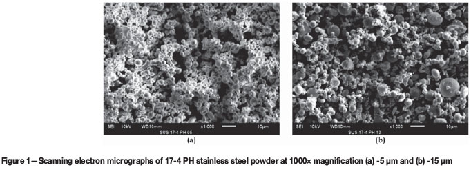
A bimodal 17-4 PH stainless steel powder material was prepared for this work. It consisted of -15 μm and -5 μm powder materials blended in a 75:25 weight ratio, respectively; both materials were supplied by Atmix Corp. JP. Figure 1 shows the representative powder particle sizes and spherical morphologies as observed under a JEOL JSM - 6510 scanning electron microscope (SEM).
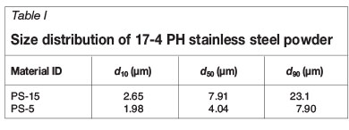
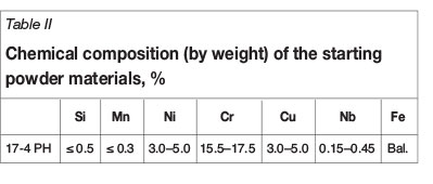
Table I summarizes the starting metal powder particle sizes measured using a laser scattering particle size analyser (Microtrac Bluewave). The material identification codes PS-15 and PS-5 represent the particle sizes -15 μm and -5 μm, respectively. Table II shows the typical chemical compositions of the metal powder materials as obtained from the supplier's data specification sheets.
An injection-ready MIM feedstock was prepared by compounding the bimodal 17-4 PH stainless steel powder material with a proprietary wax-polymer binder system developed at the CSIR (Machaka and Chikwanda, 2015). The binder system consists of a major fraction of paraffin wax, a blend of low-density polyethylene, polypropylene and a stearic acid surfactant of less than 1 wt.% of the binder system composition. The feedstock was prepared in a sigmatype blade mixer for at least 1 hour at 140°C in air.
Upon cooling, the feedstock was appropriately granulated and injection-moulded into standard MPIF 'dogbone' tensile specimens. The injection moulding was done at 140°C using an ARBURG Allrounder 270U 400-70 injection moulding machine.
Debinding of green parts was performed in two steps. The first step was solvent extraction of the low-molecular-weight solvent-soluble binder components in n-heptane (Merck) at 60°C for up to 24 hours. The sample was subsequently dried before being weighed to obtain the percentage weight loss of the binder. The second step was thermal decomposition of the backbone binder during the pre-sintering cycle. This was accomplished in a Carbolite tube furnace under a controlled flowing argon atmosphere at 550°C. The mechanism of this thermal debinding procedure has been reported elsewhere (Machaka and Chikwanda, 2015; Machaka, Seerane and Chikwanda, 2014; Seerane, Chikwanda and Machaka, 2015)
The thermally debound components were sintered at 1300°C for 4 hours followed by furnace cooling. The argon gas flow was maintained at 1.0 L/min. The microstructure, density, microhardness and tensile properties of the sintered components were investigated accordingly.
DPR sample preparation
Ti-HDH 100 mesh (-150 μm) powders supplied by Chengdu Huarui Industrial in China were used. The powders were rolled in a modified Schwabenthal Polymix 150T rubber mill with a roll diameter of 170 mm. The rolling speed was set at 10 r/min with a roll gap of 0.3 mm. The set strip width was varied at 20, 50 and 100 mm.
The masses of the strips were measured using an Ohaus Explorer balance, the length and width were measured using a Vernier caliper and the thickness was measured using a TA micrometer screw gauge. Five measurements were taken for each parameter and an average value used. The green density of each strip was calculated using the measured mass, length, width and thickness of the compact strips.
Sintering was carried out in a Carbolite tube furnace at 1300°C for 3 hours followed by furnace cooling. Argon was used as an inert atmosphere at 1 L/min. After sintering, the density of each strip was measured using an Ohaus Explorer density determination kit based on the Archimedes principle according to ASTM standard B311. The sintered compacts were sectioned into several pieces, mounted, ground and polished according to standard metallography procedures. The microstructures of the polished samples were recorded using a DM5000 optical microscope with Image Pro-AMS 603 software for recording the micrographs.
X-ray computed tomography scanning
Representative as-moulded green component, dried brown components and final sintered components were probed by means of XCT to investigate the evolution of the pores throughout the stages of MIM processing (injection moulding, debinding and sintering). For the DPR process, sintered samples that were 20, 50 and 100 mm wide were probed to investigate the residual porosity in terms of the position and distribution.
The X-ray computed tomography scans were conducted at the Micro-focus X-ray Radiography/Tomography (MIXRAD) laboratory using the NIKON XTH 225ST system based at the South Africa Nuclear Energy Corporation (Necsa) (Hoffman and Beer, 2012). The high-resolution system consists of a tungsten target with a 3.7 μm spot size with a variable energy potential of approximately 25 to 225 kV. The maximum resolution achievable at the detector is 200 μm. Each sample was scanned at a potential of 115 kV and beam current of 100 A to obtain beam penetration > 10% from background. During the scan the sample rotated in equal angular steps through 360° to produce 1000 radiographs at each step angle, which were then reconstructed using the CT-Pro 3D-reconstruction software (Hoffman and Beer, 2012). The reconstruction process transforms the acquired 2D radiographs into a virtual 3D volume that is an exact digital copy of the sample. This virtual 3D volume was analysed using VGStudioMAX (ver. 2.2) rendering software, which allows rendering of the sample in 3D. The background is represented by darker grey values, whereas the sample has lighter/bright grey values. This grey value difference was used to determine porosity distribution within the samples.
Results and discussion
MIM parts and properties
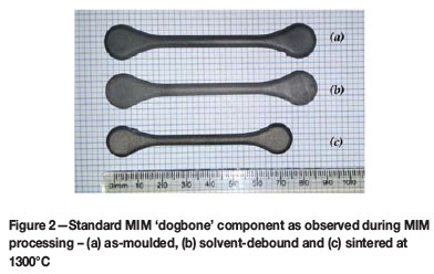
Figure 2 depicts the differences between the as-moulded green, solvent-debound and sintered components. The surface appearance of specimens (a-c) gives an indication of the binder lost from the green state to the sintered state and this equates to the level of shrinkage that occurred. Specimen (b) underwent solvent debinding and no significant shrinkage difference was observed relative to the as-moulded part. The linear shrinkage of the sintered sample (Figure 2 (c)) was calculated to be 12.5%.
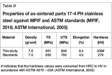
The as-sintered dogbone specimens were used for tensile tests without any preparation. The mechanical properties of unimodal 17-4 PH stainless steel feedstock specimens are reported elsewhere (Seerane, Ndlangamandla and Machaka, 2016). Table III summarizes the mechanical properties of metal-injection-moulded 17-4 PH stainless steel obtained in this study. The values are well above minimum standard stipulated values (MPIF, 2016; ASTM International, 2005).
The densities of the sintered specimens were determined according to ASTM B311 (Archimedes method). Specimen hardness was determined at room temperature using the Vickers hardness testing procedure.
MicroCT scanning of MIM parts
Unless purposely intended (Chen et al., 2016), sintered MIM parts are typically sintered to high density (95-99%); a small amount of residual porosity may arise from (a combination of) poorly formulated feedstock, the debinding process, gas entrapment during sintering and/or incomplete sintering of metal particles (German and Bose, 1977; German. 2013; Machaka, Seerane and Chikwanda, 2014).
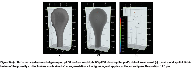
Figure 3 to Figure 5 illustrate the XCT 3D analysis of reconstructed green, solvent-debound and sintered MIM parts. The three steps conducted in each case involved (a) reconstructing the 3D surface from raw data, (b) histogram segmentation and identification of the open pores and interior pores and inclusions from the background and (c) separating the various individual components identified in Figure 2 for structural properties such as relative volume, spatial distribution, domain size and shape distributions, specific area, interconnectedness and spatial orientation.
The reconstructed surface in Figure 3a shows the holistic surface integrity of the green part and can also be used as a versatile inspection tool (for obvious moulding defects and resolvable surface porosity) and for dimensional measurements. In Figure 3b, the 3D distribution surface and interior pores in the green part volume are determined, while in Figure 3c the identified defects are analysed in isolation. The results aid the visualisation of the size and spatial distribution of injection moulding defects. A maximum defect volume of approximately 0.05 mm3 was identified; however, no MIM-specific standards have been developed to determine if such defect volumes are reparable in subsequent steps. It is has been shown that some defects do occur in green parts and these defects can be avoided or controlled by adopting good tooling design and optimizing injection moulding parameters (see Nor et al., 2009).
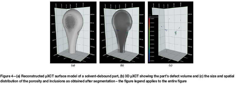
Figure 4a shows a reconstructed 3D surface image of the solvent-debound part that shows no evidence of surface porosity. From Figure 3a, it is also apparent that the shape form and dimensions of the green part are largely retained in the brown part. The visualization of the debinding defects and resulting surface porosity shows a two-fold increase in the relative pore density to approximately 0.10 mm3 in Figures 4b and 4c. This observation is expected since the extraction of the soluble binder during solvent debinding is known to be the source of porosity in the brown part (Ji et al., 2001; Tsai and Chen, 1995). Hwang, Shu and Lee (2005) have also demonstrated that pore channels develop and the average pore size increases as solvent debinding proceeds.
Figure 4b shows remarkable differences between the surface regions and the interior due to varying material density. This difference can be used to determine porosity distribution towards the sample surfaces arising from the development of pore channels and increasing average pore size during solvent debinding (Hwang, Shu and Lee, 2005).
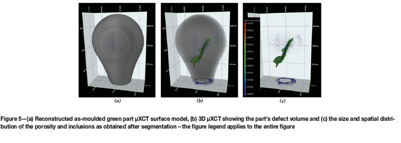
Perhaps the most compelling evidence for the use of tomographical probing techniques to non-destructively investigate the 3D internal structure of MIM-prepared 17-4 PH stainless steel is shown in the analysis of the sintered part illustrated in Figure 5. Figure 5a shows a reconstructed 3D surface image of a selected sintered part exhibiting only some occurrences of open pores. Figure 5b and Figure 5c however reveal the existence of an uncharacteristically large irregular subsurface feature with a maximum defect volume of approximately 1.00 mm3.
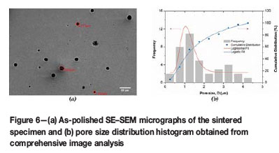
MIM-fabricated 17-4 PH stainless steel parts are intrinsically susceptible to porosity (Murray et al., 2011; James, 2015) which arises from innumerable sources during MIM processing. However, after sintering, the pores are typically near-spherical in morphology; see Figure 6a for example. The origin of the 'uncharacteristically large irregular pore' feature is attributed to either incomplete die cavity filling during the injection moulding stage or (most probably) a combination of pore formation due to gas entrapment (thermal debinding evolved products) during sintering (German and Bose, 1977) and the shrinkage porosity, since it is located in the thickest section of the part. Such features are uncommon and are therefore seldom reported. The observed open surface pores after sintering can be attributed to either the residual porosity from solvent debinding, voids remaining after thermal debinding, or the evaporation of alloy elements (chromium and manganese) due to their high vapour pressure during high-temperature sintering (Murray et al., 2011).
Microscopy of MIM parts
A typical secondary electron SEM micrograph of the as-polished 17-4 PH sintered specimen is presented in Figure 6a. The pores are evenly distributed and primarily spherical in morphology; indicating that at 1300°C, sintering progressed to its final possible stages.
The pore sizes and distribution were determined by evaluating the SEM micrographs using ImageJ software (Schindelin et al., 2015). The pore size distribution histogram obtained from comprehensive image analysis is presented in Figure 6b. The pore sizes observed exhibit a lognormal peak (distribution mode approx. 1.0 μm) with the largest pores typically less than 4.5 μm in diameter. The largest pore sizes obtained from the image analysis are much smaller than those detected by the lowest resolution of 10 μm that can be achieved by the μXCT machine even after having compromised on the size of the piece to be analysed.
DPR parts and properties
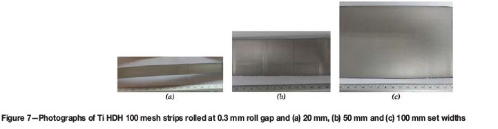
Ti-HDH 100 mesh (-150 μm) powders were supplied by Chengdu Huarui Industrial Co., Ltd in China. The powder particle sizes and morphology are reported elsewhere (Motsai, 2016). The powders were roll compacted. Figure 7 shows photographs of rolled strips that are 20, 50 and 100 mm wide. By observation, the rolled strips demonstrate good densification without exhibiting obvious signs of warping, cracking and alligatoring, which are typical rolling defects (Park et al., 2012; Joo et al., 2005).
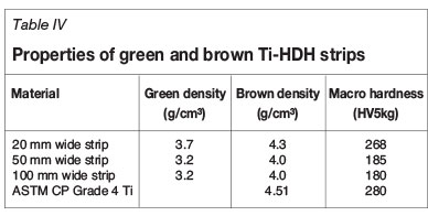
Table IV summarizes the properties of the green (rolled) and brown (sintered) Ti-HDH strips. The hardness values for the higher density 20 mm strips were closer to the commercially pure Ti grade 4. The hardness values were reduced for the lower density 50 mm and 100 mm strips. A reduction in hardness has been observed in powder metallurgy components and is due to the amount of pores in the components (Dutta and Bose, 2012). The density results show an increase after sintering. However, full density was not achieved by sintering for all the strips.
Microscopy ofDPR parts
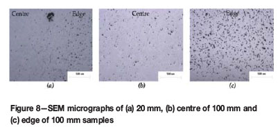
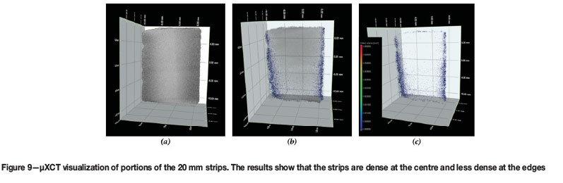
Sintering of the strips in Figure 7 was carried out. Results of the sintering studies showed that full density was not achieved at the selected sintering condition used. These measured densities do not provide any information regarding the position and distribution of the pores within the strips. Therefore, microscopy was carried out to determine the distribution of porosity within the strips. The 20 mm strip was cut in half along the rolling direction, mounted and polished. Figure 8a shows a micrograph taken to include the edge of the strip. It can be seen that the strip had a lower density at the edge (right side of the micrograph) which increased towards the centre (left side of micrograph) of the strip. For samples larger than 20 mm, several samples were cut from the edge, midway between edge and centre and centre of the strips. Figure 9b and 9c show the micrographs of the 100 mm wide strip from the centre and the edge of the strips respectively. It is clear from the micrographs that the porosity pattern is similar to that of the 20 mm strips was observed, with the density being higher at the centre and lower at the edge of the compact.
It was also observed that after sintering, warping of the strips occurred. The microscopy studies showed that the sintered strips had non-uniform density across the width, which implies non-uniform density in the green strips as well. Density variations within the green strip are known to create residual stresses and cause different densification rates during sintering, which ultimately cause the dimensional distortions (Khoei, 2995). It is therefore plausible that the observed dimensional distortions (warping) of the sintered strips in this study are a consequence of the non-uniform density within the strips.
MicroCT scanning of DPR parts
In order to understand the extent of density variations in the DPR strips, an alternative XCT scanning technique was used.
The XCT scanning technique was evaluated for use as a nondestructive test for detecting non-uniform densities, with the additional benefit of elimination of the tedious microscopy studies required to map DPR strips that are long and wide.
By way of illustration, Figure 9 shows the visualization of 3D XCT data on a section of the 20 mm wide sintered rolled strip. Similarly to the MIM XCT results shown in Figure 3, three analysis steps were conducted in each case involving (a) reconstructing the 3D surface, (b) the identification of the open pores, interior pores and inclusions and (c) isolating the open pores, interior pores and inclusions identified in (b) for structural properties and visualisation
The reconstructed surface in Figure 9a shows the surface defects such as chipping of the strip at the edges and the different grey levels characteristic of the varying densities. No other rolling defects are detected in the strip. Figure 9b shows the 3D distribution of pores in the sintered volume while Figure 9c shows the pores in isolation. The result confirms the presence of density variations in the sintered DPR strips as shown by the microscopy studies. Furthermore, XCT was able to show that the pores are concentrated at the edges of the strips, with some detected in the transverse direction to rolling as is typical of compacts produced by non-optimal rolling conditions. Using traditional techniques to detect these density changes, sections of the strips are cut up, mounted and polished to look for porosity differences in the compacts. This process is destructive and tedious. In this study the visualization of the density variation and edge porosity is made clear in Figure 9b and 9c.
Results from this study show that μXCT scanning is suitable for characterizing small-sized samples such as the 20 mm wide strip shown in Figure 9. However, when the examination of bigger samples such as the 50 and 100 mm wide strips was attempted, the overall instrument resolution was compromised, making it difficult to resolve the pore structures. Owing to the size effects, it was necessary to section wider or longer strips to small sections, requiring a large number of scans to map out a significant size of the compacts. This diminished the benefit of non-destructive testing and ability to map out the densities for wider and longer strips.
Conclusions
An important advantage of the μXCT method is that no specific sample preparation is needed. Detailed quantitative and qualitative information obtained in this study relating to the 3D internal structure of MIM-prepared 17-4 PH stainless steel and DPR-prepared parts shows that XCT is a powerful non-invasive and non-destructive measurement technique that can be very useful for research purposes. Structural parameters such as relative volume, spatial distribution, size and shape distributions, specific area, connectivity and orientation are resolved with the benefit of colour-coded visualization of individual pores and inclusions according to volume.
Analysis of MIM and DPR parts demonstrated:
i. μXCT scanning conducted in this study demonstrated the capabilities by detecting the amount, position, and distribution of the pores in MIM and DPR parts, as well as detecting sub-surface features such as shrinkage pores as seen on the sintered MIM parts
ii. Comparative μXCT and SE-SEM shows that the spatial resolution of the μXCT will limit the smallest detectable variations in the as-produced porous samples. Features smaller than the resolution will not be measured correctly. Based on the findings, it is therefore, concluded that a higher resolution scan such as X-ray nano-tomography has to be used to study porosity evolution in these parts
iii. The examination of different pore structures in wider or longer rolled strip samples (such as the 50 and 100 mm) with μXCT was not successfully achieved with the required resolution, without the need to section the wider or longer strips into small sections, thus requiring a large number of scans.
Acknowledgements
The contributions of Ntate Sam Papo, Mandy Seerane, Hilda Chikwanda and Pierre Rossouw are duly recognized. This work is funded by the DST and the CSIR. NSM acknowledges the NRF for financial support through the DST-NRF Internship Programme. The authors are also indebted to Atmix Corp. (JP) for the supply of powder materials used in the preparation of MIM components.
References
Aldica, G., Tiseanu, I., Badica, P., Craciunescu, T. and Rindfleisch, M. 2010. X-ray micro-tomography as a new and powerful tool for characterization of MgB2. Superconductor. Juiz, A.M. (ed.). Sciyo. [ Links ]
ASTM International. 2005. ASTM B883-05, Standard Specification for Metal Injection Molding (MIM) Ferrous Materials. West Conshohocken, PA. [ Links ]
ASTM International. 2003. ASTM A370-03a, Standard Test Methods and Definitions for Mechanical Testing of Steel Products. West Conshohocken, PA. [ Links ]
Barriere, Τ., Liu, B. and Gelin, J.C. 2003. Determination of the optimal process parameters in metal injection molding from experiments and numerical modeling. Journal of Materials Processing Technology, vol. 143-144. pp. 636-644. [ Links ]
Bateni, A. Parvin, N. and Ahmadi, M. 2011. Density evaluation of powder metallurgy compacts using in situ X-ray radiography. Powder Metallurgy, vol. 54, no. 4. pp. 533-536. [ Links ]
Cantin, M.A. and Gibson, G.M.D. 2015. Titanium sheet fabrication from powder titanium. Powder Metallurgy. Qian, M. and Froes, F.H. (eds.). Elsevier. pp. 383-403. [ Links ]
Cantin, G.M.D., Kean, P.L., Stone, N.A., Wilson, R., Gibson, M.A., Yousuff, M., Ritchie, D. and Rajakumar, R. 2011. Innovative consolidation of titanium and titanium alloy powders by direct rolling. Powder Metallurgy, vol. 54. pp. 188-192. [ Links ]
Cantin, D., Kean, P., Stone, N.A., Wilson, R,. Gibson, M.A., Ritchie, D. and Rajakumar, R. 2010. Direct powder rolling of titanium. Proceedings of Titanium 2010, Orlando, Florida, 3-6 October 2010. International Titanium Association, Northglenn, CO. [ Links ]
Chen, J., Chen, L., Chang, C.-C., Zhang, Z., Li, W., Swain, M.V. and Li, Q. 2016. Micro CT based modelling for characterising injection moulded porous titanium implants. International Journal for Numerical Methods in Biomedical Engineering. [DOI: 10.1002/cnm.2779]. [ Links ]
Chikosha, S., Shabalala, T.C. and Chikwanda, H.K. 2014. Effect of particle morphology and size on roll compaction of Ti-based powders. Powder Technolology, vol. 264. pp. 310-319. [ Links ]
De Chiffre, L., Carmignato, S., Kruth, J.P., Schmitt, R. and Weckenmann, A. (2014). Industrial applications of computed tomography. CIRP Annals - Manufacturing Technology, vol. 63, no. 2. pp. 655-667. [ Links ]
Du Plessis, A., le Roux, S.G., Booysen, G. and Els, J. 2016. Directionality of cavities and porosity formation in powder-bed laser additive manufacturing of metal components investigated using X-ray tomography. 3D Printing and Additive Manufacturing, vol. 3, no. 1. pp. 48-55. [ Links ]
Dutta, G. and Bose, D. 2012. Effect of sintering temperature on density, porosity and hardness of a powder metallurgy component. International Journal of Emerging Technology and Advanced Engineering, vol. 2, no. 8. pp. 121-123. [ Links ]
Fang, W., He, X., Zhang, R., Yang, S. and Qu, X. 2014. The effects of filling patterns on the powder-binder separation in powder injection molding. Powder Technolology, vol. 256. pp. 367-376. [ Links ]
Froes, F.H., Mashl, S.J., Hebeisen, J.C., Moxson, V.S. and Duz, V.A. 2004. The technologies of titanium powder metallurgy. JOM, vol. 56. pp. 46-48. [ Links ]
German, R. 2013. Progress in titanium metal powder injection molding. Materials, vol. 6. pp. 3641-3662. [ Links ]
German, R.M. 1990. Powder injection molding. Metal Powder Industries Federation, Princeton, NJ. [ Links ]
German, R.M. and Bose, A. 1977. Injection Molding of Metals and Ceramics. Metal Powder Industries Federation Princeton, NJ. [ Links ]
Heldele, R., Rath, S., Merz, L., Butzbach, R., Hagelstein, M. and Hausselt, J. 2006. X-ray tomography of powder injection moulded micro parts using synchrotron radiation. Nuclear Instruments and Methods in Physics Research Section B: Beam Interactions with Materials and Atoms, vol. 246, no. 1. pp. 211-216. [ Links ]
Hoffman, J.W. and Beer, F.C.D.E. 2012. Characteristics of the micro-focus X-ray tomography system at the MIXRAD facility at NECSA in South Africa. Proceedings of the 18th World Conference on Nondestructive Testing, Durban, South Africa, 16-20 April 2012. South African Institute for Non-Destructive Testing. http://www.ndt.net/article/wcndt2012/papers/37_wcndtfinal00037.pdf [ Links ]
Hwang, P.S.K..S., Shu, G.J. and Lee, H.J. 2005. Solvent debinding behavior of powder injection molded components prepared from powders with different particle sizes. Metallurgical and Materials Transactions',vol. 36 no. 1. pp. 161-167. [ Links ]
James, W.B. 2015. ASM Handbook, vol. 7. 922 p. [ Links ]
Joo, S.H., Chang, H.J., Bang, W.H., Han, H.N. anD Oh, K.H. 2005. Analysis of alligatoring behavior during roll pressing of DRI powder with flat roller and indentation-type roller. Materials Science Forum, vol. 475-479. pp. 3223-3226. [ Links ]
Kara , Ł. and Matula, G. 2015. Review of innovation in using X-ray tomography for non-destructing analysing of the green parts. Journal of Achievements in Materials and Manufacturing Engineering, vol. 73, no. 2. 139 p. [ Links ]
Khoei, A. 2005. Computational Plasticity in Powder Forming Processes. Elsevier, Tehran. [ Links ]
Kohn, H.W. 1972. Non-destructive testing. Journal of General Education, vol. 24. pp. 176-178. [ Links ]
Lí, Y., Li, L. and Khalil, K.A. 2007. Effect of powder loading on metal injection molding stainless steels. Journal of Materials Processing Technology, vol. 183. 432 p. [ Links ]
Jí, C.H., Loh, N.H. Khor, K.A. and Tor, S.B. 2001. Sintering study of 316L stainless steel metal injection molding parts using Taguchi method: final density. Materials. Science and Engineering A, vol. 311. pp. 74-82. [ Links ]
Lunel, M. 2013. Structure Characterisation of catalysts using X-ray micro-computed tomography, PhD thesis, university of Birmingham, united Kingdom. [ Links ]
Ma, J., Lí, A. and Tang, H. 2016. Study on sintering mechanism of stainless steel fiber felts by X-ray computed tomography. Metals, vol. 6, no. 1. 18 p. [ Links ]
Machaka, R. and Chikwanda, H.K. 2015. Kinetics of titanium metal injection moulding feedstock thermal debinding. Proceedings of the Seventh International Light Metals Technology Conference, (LMT 2015), Port Elizabeth, South Africa, 27-29 July 2015. Chikwanda, H.K..and Chikosha, S. (eds.). pp. 1-6. [ Links ]
Machaka, R., Seerane, M. and Chikwanda, H.K. 2014. Binder development for metal injection moulding: a CSIR perspective. Advances in Powder Metallurgy and Particulate Materials - 2014. Proceedings of the 2014 World Congress on Powder Metallurgy and Particulate Materials, PM 2014, orlando, Florida, 18-22 May. Metal Powder Industries Federation. pp. 43-58. [ Links ]
Maire, E., Buffière, J.Y., Salvo, L., Blandin, J.J., Ludwig, W. and Létang, J.M. (2001). X-ray micro-tomography an attractive characterisation technique in materials science. Advanced Engineering Materials, vol. 3, no. 8. pp. 539-546. [ Links ]
Martin, P., Haskins, J., Thomas, G. and Dolan, K. 2003. Advanced NDE techniques for powder metal components. Proceedings of the International Conference on Powder Metallurgy and Particulate Materials (PM2TEC 2003), Las Vegas, Nevada, 8-12 June 2003. Metal Powder Industries Federation, Princeton, NJ. [ Links ]
Motsai, T.M., Chikosha, S., Bhero, S. and Chikwanda, H.K. 2016. Investigation of pressing and sintering of Ti-HDH powder. Proceedings of Ferrous 2016, Ferrous and Base Metals Development Network (FMDN), (In Press). [ Links ]
MPIF. 2016. MPIF Standard 35, Materials Standards for Metal Injection Moldec Parts. 2016 edn. Metal Powder Industries Federation (MPIF), Princeton, NJ. [ Links ]
Murray, K., Coleman, A.J., Tingskog, T.A. and Whychell D.T. Sr. 2011. Effect of particle size distribution on processing and properties of MIM 17-4PH. International Journal of Powder Metallurgy, vol. 47, no. 4. pp. 21-28. [ Links ]
Mutina, A. and Koroteev, D. 2012. Using X-ray microtomography for the three dimensional mapping of minerals. Microscopy and Analysis, vol. 26, no. 2. pp. 7-12. [ Links ]
Nor, N.H.M., Muhamad, N., Ismail, M.H., Jamaludin, K.R., Ahmad, S. and Ibrahim, M.H.I. 2009. Flow behaviour to determine the defects of green part in metal injection molding. International Journal of Mechanical and Materials Engineering, vol. 4. pp. 70-75. [ Links ]
O'Brien, R.C. and James, W.B. 1988. A review of nondestructive testing methods and their applicability to powder metallurgy processing. MPIF Seminar on Prevention and Detection of Cracks in Ferrous P/M Pads, International Powder Metallurgy Conference and Exhibition. pp. 1-17. [ Links ]
Park, N.K., Lee, C.H., Kim, J.H. and Hong, J.K. 2012. Characteristics of powder rolled and sintered sheets made from HDH Ti powders. Key Engineering Materials, vol. 520. pp. 281-288. [ Links ]
Peterson, S. 2010. Investigation of the Hot deformation of Sintered Titanium Compacts Produced from Direct reduction Powder. Masters thesis, University of Cape Town, South Africa. [ Links ]
Qian, Mn. 2010. Cold compaction and sintering of titanium and its alloys for near-net- shape or preform fabrication. International Journal of Powder Metallurgy, vol. 46, no. 5. pp. 29-44. [ Links ]
Ro, D.H., Toaz, M.W. and Moxson, V.S. 1983. The direct powder-rolling process for producing thin metal strip. JOM, vol. 35, no. 1. pp. 34-39. [ Links ]
Schindelin, J., Rueden, C.T., Hiner, M.C. and Eliceiri, K.W. 2015. The ImageJ ecosystem: An open platform for biomedical image analysis. Molecular Reproduction and Development, vol. 82, nos. 7-8. pp. 518-529. [ Links ]
Seerane, M., Chikwanda, H. and Machaka, R. 2015. Determination of optimum process for thermal debinding and sintering using Taguchi method. Materials Science Forum, vol. 828-829. 138 pp. [ Links ]
Seerane, M., Ndlangamandla, P. and Machaka, R. 2016. The influence of particle size distribution on the properties of metal-injection-moulded 17-4 PH stainless steel. Proceedings of Ferrous 2016, Ferrous and Base Metals Development Network (FMDN), (In Press). [ Links ]
Sotomayor, M.E., Várez, A. and Levenfeld, B. 2010. Influence of powder size distribution on rheological properties of 316L powder injection moulding feedstocks. Powder Technology, vol. 200, nos. 1-2. pp. 30-36. [ Links ]
Tammas-Williams, S., Zhao, H., Leonard, F., Derguti, F., Todd, I. and Prangnell, P.B. 2015. XCT analysis of the influence of melt strategies on defect population in Ti-6Al-4V components manufactured by selective electron beam melting. Materials Characterization, vol. 102. pp. 47-61. [ Links ]
Tsai, D.S. and Chen, W.W. 1995. Solvent debinding kinetics of alumina green bodies by powder injection molding. Ceramics International, vol. 21, no. 4 pp. 257-264. [ Links ]
Weber, O., Rack, A., Redenbach, C., Schulz, M. and Wirjadi, O. 2011. Micropowder injection molding: investigation of powder-binder separation using synchrotron-based microtomography and 3D image analysis. Journal of Materials Science,vol. 46, no. 10. pp. 3568-3573. [ Links ]
Yang, S.-D., Zhang, R.-J. and. Qu, X.-H. (2015a). X-ray tomography analysis of aluminum alloy powder compaction. Rare Metals. pp. 1-7. [ Links ]
Yang, S., Zhang, R. and Qu, X. 2015b. Optimization and evaluation of metal injection molding by using X-ray tomography. Matererials Characterization, vol. 104. pp. 107-114. [ Links ]
This paper was first presented at the AMI Ferrous and Base Metals Development Network Conference 2016 19-21 October 2016, Southern Sun Elangeni Maharani, KwaZulu-Natal, South Africa.

