


Servicios Personalizados
Articulo
 Inglés (pdf)
 Articulo en XML
 Referencias del artículo
Indicadores

Links relacionados
-
 Citado por Google
 -
 Similares en Google
Compartir

 Permalink
Journal of the Southern African Institute of Mining and Metallurgy
versión On-line ISSN 2411-9717
versión impresa ISSN 2225-6253
J. S. Afr. Inst. Min. Metall. vol.114 no.10 Johannesburg oct. 2014
6TH SOUTHERN AFRICAN ROCK ENGINEERING SYMPOSIUM
Testing tendon support units under a combination loading scenario
N.L. Ayres; L.J. Gardner
Impala Platinum Limited
SYNOPSIS
Tendon support systems have been successfully used to stabilize excavations. Tendon support systems are routinely designed using the axial load-bearing capacity of tendons, namely the tensile strength. To attain tensile strength the tendon must be loaded along its length, which often does not occur in practice. Tendons should optimally be installed at 90° to the surface of the excavation to achieve maximum penetration depth, yet this is often not physically or practically possible, and installations at angles less than 90° occur.
Furthermore, the intersection of geological features within the rock mass frequently results in complex loading situations on tendons. The position and angle at which loading occurs results in different combinations of tensile and shear forces acting on the tendon, which can impact on the support performance of each unit and ultimately the whole system. All factors that influence the support system should be understood and taken into account to ensure a sound support design.
Combination loading situations are further investigated and tested to obtain a better understanding of the mechanisms involved and the effects on tendon load-bearing capacity. Tendon support units were tested at different installation angles to establish the tendon performance, mechanical behaviour, and load capacity during these loading situations. The results and outcomes are aimed at providing rock engineers with additional data and improved understanding of how tendons could perform under certain conditions.
Keywords: tendon support, combination loading, shear strength, tensile strength.
Introduction
Tendon support units are primarily tested for tensile and shear strength and performance. Hangingwall support designs are frequently based on the axial load-bearing capacity of the tendons (i.e. the pure tensile strength of the tendon), rather than the tendon's load-bearing capability in shear (which is usually significantly lower than the tensile strength). The load-bearing capacity and support performance of tendons under different combination loading situations and installation angles should be investigated and quantified to ensure this information can be incorporated into the fundamentals of the support design. This becomes even more significant when geological structures are known to be present.
In an ideal world, tendons would be installed at 90° to the surface of the excavation, yet this is sometimes not physically or practically achievable. Across the industry, accepted installation angles typically vary between 70° and 90° to the hangingwall, with even lower angles being specified (and/or measured) on occasion. Justification and support performance information for these different installation angles should be available for the support design. At all installation angles (including 90°) the varied nature of geological features (including joints) can result in various combination loading situations and different loading angles on a tendon. This does not create pure tensile or shear loading, but results in various combinations of concurrent tensile and shear loading on the tendon, influencing the performance characteristics used for the design.
Limited information and test results are available for tendon performance under combination loading. A testing programme of combination loading on tendons was therefore conducted. By sharing the outcomes and difficulties encountered in performing combination load testing on friction tendon support units, the authors hope to assist in advancing the combination load testing method towards a standardized international test method for all types of support tendons.
Such a standardized combination test method will deliver more appropriate support capacity data to better address varied geological influences, allow for better support designs, and assist with back-analysis after failures. This would also provide manufactures with a standard to test their products against, and rock engineers with a constant base for comparison between support units, as well as more reliable criteria for selection of the appropriate support unit type for a specific rock mass environment.
Process for determining testing method for combination loading
Owing to the limited literature dealing with combination loading, together with the lack of a formal testing method, the testing jigs and test method for combination load testing were developed by trial and error. Several factors were investigated to determine the basis of the testing method, including:
► Typical installation angles and how these influence tendon loading
► Geological and mining-induced structures/discontinuities within the rock mass and how these influence tendon loading, particularly when combined with a range of installation angles
► The type of tendon being tested
► Characteristics of the testing machine
► Simulating how the behaviour of an installed tendon is affected by the in situ rock mass environment, particularly with regard to the loading forces and directions.
Installation angle
In Figure 1, a number of installation angles are illustrated, ranging from -90° to +90° from the horizontal. All installation angles between these extremes are possible. It can be seen that, due to the layout of an excavation, a number of different installation angles are required. In certain situations, some installation angles are not achievable in practice due to limitations of excavation size and/or orientation. In particular, it should be noted that in a 35° inclined excavation the typical tendon installation of 90° to the hangingwall results in an installation angle of less than 90° to the horizontal (as illustrated in Figure 1, this results in a 55° installation angle).

Geological structures and rock blocks
Most rock masses are divided into blocks of various sizes, shapes, and orientations by joints and other geological structures. All blocks are subjected to the influence of gravity, which always acts vertically. The position and orientation at which the excavation intersects the blocks, together with the orientation of the structures, results in various loading directions as illustrated in Figure 2.

Tendon A in Figure 2 is installed vertically and at 90° to the hangingwall, and should be subjected to a pure tensile load under the influence of gravity. However, due to the orientation of the geological structures, the resultant loading force is not vertical and a combination of tensile and shear loading now acts on the tendon. This, together with the range of tendon installation angles, leads to an infinite number of possible loading situations.
Testing of all installation angles and joint intersections is neither practical nor possible, and therefore only selected angle intervals were tested. Results can be interpolated between testing intervals. It should be noted that in many instances during mining, induced stresses can influence excavations from any direction and thereby further complex loading situations are created in a three-dimensional environment. Combination load testing is a simplification as only a two-dimensional loading situation is simulated. Different failure modes such as shear, dilation, cantilever, and toppling are possible, although only the shear and dilatory failures are discussed in this paper.
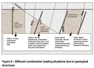
Movement along geological structures will occur as either shearing (where lateral movement occurs along the joint planes) or dilation (where the joint planes move away from each other and open up). Pure tensile and pure shear loading occur at 0° and 90° respectively, as illustrated in Figures 3 and 4. Combination loading occurs between 0° and 90° - this loading is either predominantly tensile (tendon is extended) or predominantly compressional loading (tendon is shortened). The combination of the tensile and shear load components varies as the loading angle changes in relation to the tendon's long axis.


Where the force acts parallel to the failure plane, shearing occurs (as illustrated in Figure 3). Loading will then be by either tensile or compressional shear. In Figure 3, the tensile shear zone (where the tendon extends) is to the right of 0°, and the compressional shear zone, where the tendon will be compressed along the failure plane, to the left of 0°. At 45°, the shear, tension, and compression components are equal. This should be the inflection point at which the mechanical performance of the tendon can change.
Where the forces do not act in parallel, but rather at an angle across the failure plane, dilation occurs. Figure 4 illustrates the combination loading situations where the force acts perpendicular to a horizontal failure plane. To the left and the right of 0°, the effect on the tendon will be the same. As the load angle on the tendon changes from 0° to 90° the tensile component will decrease from maximum to zero while the shear component increases from zero to maximum.
Figure 5 further illustrates all these loading conditions occurring in situ within the rock mass. The loose block will load the tendon and any movement on the joint plane will cause the load to be concentrated at the point where the tendon intersects the structure. This will be true for friction tendons and full column grouted tendons, as they behave in the same manner. Mechanically end-anchored tendons will take up load along a greater portion or the entire length of the tendon, depending on the loading direction.
Tendon type
The type of tendon used for the testing programme was the hydraulically pre-stressed friction bolt manufactured by New Concept Mining (Pty) Ltd. For a friction tendon there is direct contact between the entire length of the tendon and the rock mass and therefore loading will be concentrated at the intersection of a structure, as previously explained. Li and Stillborg (1999) propose the concepts of 'neutral point', 'pickup length', and 'anchor length' which describe the mechanical coupling at the interface between the rock and a friction tendon. The paper discussed the shear stress and decoupling along the tendon during loading and how this affects the axial load. This provides a better understanding of the loading in a jointed rock mass and how several axial stress peaks can exist along the tendon.
The HydraboltTM and XpandaboltTM are manufactured in the same way; the difference lies in the pressure remaining in the tubular tendon after pre-stressing. The tendons are prestressed with water and the XpandaboltTM releases the water after pre-stressing, while the HydraboltTM retains the water in the tube, resulting in a stiffer support unit and a shorter critical bond length. Both tendons have a roll or 'valley' along the length of the tendon which creates a sectional profile resembling a horseshoe shape. For the tests, the 'valley' was always placed in the same direction to ensure the tested profile was constant, to counteract any possible effect of the tendon profile on the load performance.
Testing machine
As the tendons must be tested at different angles, a jig is required to hold the tendons in the required positions. A two-part steel jig (as seen in Figure 6) houses the tendon and creates the required failure plane for testing. Examination of the testing machine revealed that limited space was available for the tendon and the test jig; therefore the test jigs could not be very bulky. The stroke (i.e. the distance over which the machine can create a loading force) was limited. The clevis attachment points on the machine were aligned vertically. The jig attachment flanges and holes, as well as the failure plane, had to intersect this vertical line so that forces were transmitted to the tendon and not to the test jig. Any influence from the test jig would skew the results of the tendon performance. The jig attachment flanges and holes had to be correctly aligned so that the jig portions, failure plane, tendon, and the loading direction all lined up.

Attachment flanges tended to be large, to enable lining up the holes and failure plane, yet they needed to be kept as small as possible to utilize the stroke of the testing machine. As the angle of installation tended toward 90°, the holes in the attachment flanges grew further apart; this was much more pronounced in the vertical failure plane testing. Many of the tendons in the 70° and 80° range fitted into the machine but too short a stroke was available to test the tendons successfully; so the test set was incomplete.
Testing of the tendons at different installation angles, and therefore under different combination loading situations or different combinations of tensile and shear load, was made possible by creating failure planes (one vertical and one horizontal) that intersected the tendon axis at different angles, as shown in Figure 6 (installation angles of 45° (left) and 70° (right) are shown). This allowed the force or load to act at different angles across the tendon axis and thereby produced different combinations of tensile and shear force components. A tendon installed in the test machine at 60° installation angle with a horizontal failure plane is shown in Figure 7.

The test machine generates either a compressional or tensile force in a vertical direction. To achieve shear or lateral movement the force must act parallel to the failure plane and the failure plane must therefore be vertical, as seen in Figure 6. All tests where the failure plane was vertical are referred to as vertical tests. The vertical failure plane intersected the tendon axis at different angles and this in turn related to different installation angles. All possible configurations could be achieved with this set-up. The tensile force component increased as the intersection angle between the failure plane and the tendon axis decreased from 90° towards 0°. Jig configurations allowed for the testing of tensile shear only - no compressional shear was tested in the investigation.
To achieve dilation or opening up of joints, where forces act perpendicular to the failure plane, the failure plane had to be horizontal, as seen in Figure 6; therefore these tests are referred to as horizontal tests. The force acted in the gravitational direction and this configuration resulted in predominantly tensile forces. The failure plane intersected the tendon axis at different angles and this in turn related to different installation angles. The limited extent of the stroke on the machine did not allow for the testing of high (i.e. near-vertical) installation angles as the tendons were too long. The shear force component increased as the intersection angle of the failure plane to the tendon axis decreased from 90° towards 0°.
Bending moment and rotation have a large influence during the combination loading. In the investigation, only forces that acted parallel or perpendicular to the failure plane were investigated. Numerous other configurations can exist where the force acts at angles less than 90° to the failure plane. This can occur where the joint or failure plane is not horizontal and loading occurs under the force of gravity or the applied force direction is not vertical i.e. when a rotation or cantilever occurs. The results of tests where the applied forces act either parallel to, or perpendicularly across the joint / failure plane could possibly be interpolated to represent such situations.
The test jigs were prepared in such a manner that the applied force acted either parallel or perpendicular to the failure plane. Observations during the tests revealed that the vertical test configuration created more than just a combination of tensile and shear forces. Compression across the axis of the tendon was generated in the area of the failure plane, which increased the circumferential or radial forces due to the decrease in the circumference. During horizontal tests, a number of couples and moments occurred, which resulted in rotation.
To limit rotation of the test specimen during testing, two tendons were used to attach the jig to each clevis. Tendons were installed upside-down in the machine. The machine was zeroed at the lowest position to allow for the maximum stroke length. The upper section of the machine was raised vertically to represent a purely gravitational load. The jig was then pulled until the tendon failed, and the strength of the tendon material determined. In the case of the 90° test, the loading force acted axially along the tendon, creating a purely tensile force on the tendon.
Simulating in situ conditions
Simulation of the in situ conditions of the installed tendon and the surrounding rock mass was investigated to reproduce the loading conditions to which tendons are subjected. As the tendons being tested were friction bolts, testing was carried out at the same diameter and profile that the tendons would be when loaded underground. A jig was required to pressurize the tendons to the correct diameter. As the tendons could not be properly secured in the testing machine at different installation angles, several jigs were required.
Simulation of all in situ conditions was not possible for all components for a number of reasons, including:
► All jigs were constructed from steel tubing. The friction contact plane was thus steel (tendon) on steel (jig). The frictional load from steel on steel is much lower than that of steel on rock. Where possible, the tendon was locked into the jig to prevent slipping to test the load performance of the tendon, rather than the pullout strength
► Testing was carried out with all forces acting in the vertical plane as per gravity
► The test jigs were set up so that the centre of gravity for each test was in the centre of the failure plane. Testing did not take into account other loading situations, such as cantilevering or where the centre of gravity could be offset from the tendon axis
► The steel jigs created sharp edges along the failure planes, which would form prominent shearing/cutting edges in the vertical tests.
► The rigidity of the jigs did not allow for any breakout in the areas where the main force concentrations occur (breakout could occur here in the in situ conditions), although some deformation did occur at these points.
The test jigs were constructed to form a stiff testing system, which aimed to represent reality. During the initial tests, the rotation and deformation of the jigs revealed that the testing system was not stiff enough. A second set of jigs was constructed, using thicker steel tubing and with gussets welded along the length of the jig. Two holes (instead of one) were cut into the attachment flanges and clevises to prevent rotation.
Despite these improvements, rotation of the test tendons still occurred, indicating that the system was possibly still too soft. The progressive rotation during testing of a tendon and 30° test jig is shown in Figure 8. Deformation and failure of a second generation 65° vertical test jig with gussets is shown in Figure 9. The two attachment tendons at the attachment flange onto each clevis (as shown) failed to prevent rotation on the jig about the end of the gusset position, resulting in the test jig tearing along the attachment flange.


The results for the combination loading tests and pure tensile test are illustrated in Figure 10. This shows all the test results with the maximum loads achieved during every combination load and tensile test. The data includes the maximum loads achieved during slipping of tendons and jig failures, which introduces a large degree of variability into the data for the combination loading and tensile tests. Some of the loads therefore appear to be low and trend lines cannot be established as the data is skewed by the affected data. The data-set is not complete, and further testing is required to adequately describe the performance, yet the general trend of performance is shown.

From the failure curves for the vertical and horizontal tests respectively at the different tendon installation angles, it was noted that the curve profiles for both the HydraboltTM and X-PandaboltTM for each test type (i.e. the vertical and the horizontal tests) are similar. This indicates that the test results are comparable and that both tendon types behave similarly, but with different degrees of stiffness and load capacities.
Conclusions
Testing process
► Combination load testing is a challenging process that requires testing jigs to be prepared for different intersection angles. This can be time-consuming and costly
► Thought must be given to fitting the test jig and tendon into the testing machine and achieving the correct loading direction, so as to test the tendon performance without interference from the test jig itself
► Simulation of in situ installed tendon and rock mass conditions is difficult, but must be taken into consideration
► Robust test jigs are required, as the torque component loads affect both the test jig and testing machine adversely. A test jig machined from a solid block of metal would be more appropriate, although the resilience of such a jig for conducting multiple tests would have to be confirmed
► In a testing programme, the testing machine and a limited number of jigs should be made and tested in a first phase. Unexpected defects in the jig design and test outcomes may require modification and re-manufacture of the test jigs
► Anchoring the tendon into the jig securely and preventing slippage is problematic - this requires further experimentation for each type of tendon to be tested
► Testing at higher installation angles requires larger testing machines with longer strokes (over 1 m) to accommodate vertical alignment of the attachment points
► Photographs and videos taken during the testing process represent very valuable evidence, as they record actions that cannot be seen with the naked eye and can be revisited numerous times after testing
► If possible, physical investigation (and re-investigation) of the failed units can offer clues to the mechanism of failure and are valuable records.
Test results
► Combination loading of tendons commonly occurs in any rock mass, due to the variety of jointing orientations and tendon installation angles
► The intersection angle of the tendon and the geological structure/discontinuity, together with the position and orientation of the load, will determine the ratio of tensile component versus shear component
► Generally, the tendon failure mode tends towards tensile failure, where the tensile component is higher than the shear component
► Where the shear component is higher than the tensile component, the failure loads are much higher than for pure shear
► A component of rotation is involved in cases where the tendons tend towards tensile failure, and this can aid in wedging blocks of rock in place and preventing failures.
Finally, this testing programme represents a mere starting point for understanding the combination loading on tendons. Further testing of all types of tendons is required to reach a better understanding of the effects of combination loading on tendon support units and systems.
Acknowledgements
The authors wish to express their gratitude to the management of Impala Platinum Limited for assistance in performing the research and permission to publish the work. The authors acknowledge the contribution of New Concept Mining (Pty) Ltd for the supply of tendons, testing facilities, and assistance during testing.
Bibliography
Amin, M., Siang, K.K., and Chon, C.H. 2004. Reinforcement mechanisms of rock bolt - a laboratory investigation. Jurnal Kejuruteraan Awam, vol. 16, no. 1. pp. 1-12. [ Links ]
Brady, B.H.G., and Brown, E.T. 2004. Rock Mechanics for Underground Mining. 3rd edn. Kluwer Academic Press, Dordrecht. [ Links ]
Blanco, M.L., Hadj-hassen, F., Tijani, M., and Noiret, A. 2011. A new experimental and analytical study of grouted roofbolts. 45th US Rock Mechanics/Geomechanics Symposium, San Francisco, CA, 26-29 June 2011. [ Links ]
Crompton, B. 2003. Shear, bending and combined load testing on Hydrabolts, X-panda bolts and other support systems. New Concept Mining, Internal Report, 26 November 2003. Reference HB/0002, [ Links ]
Daehnke, A., Van Zyl, M., and Roberts, M.K.C. 2001. Review and application of stope support design criterion. Journal of the South African Institute of Mining and Metallurgy, May/June. pp. 135-150. [ Links ]
DSI DYWIDAG-Systems International P/L. Evaluation development in roofbolting. Technology in Australian Coal Mining. DSI DYWIDAG-Systems International P/L. 1-13. [ Links ]
Fernandes, N. 2007. Changing from X-Panda bolts to Hydrabolts in the ASG's, Re/Pre development. Internal report, Impala Platinum Limited. pp. 1-4. [ Links ]
Gardner, L.J. 2004. Feedback on rock engineering issues assessed during recent visit to Ngezi Mine. Internal report, Impala Platinum Limited. [ Links ]
Gaudreau, D., Aubertin, M., and Simon, R. 2004. Performance assessment of tendon support systems submitted to dynamic loading. Proceedings of the Fifth International Symposium on Ground Support, Perth, Australia, 28-30 September 2004. Villaescusa, E. and Potvin, Y. (eds.). Taylor & Francis, London. [ Links ]
Hutchinson, J.D. and Diederichs, M.S. 1996. Cablebolting in Underground Mines. BioTech Publishers, Richmond, BC, Canada. pp. 28-33, 120-125. [ Links ]
Impala Platinum. Review of Impala Platinum Mine's tendon support strategy with specific reference to protruding tendons. Internal report. [ Links ]
Joughin, W.C., Nezomba, E., Rwodzi, L., and Jager, A. 2011. Rockfall elimination Track B, a risk based approach to enhancing support design in Bushveld underground mines, Volume 1. MHSC, Safety in Mines Research Advisory Committee SIM 060201 Track B, Research agency SRK Consulting. July 2011. pp. 76-110. [ Links ]
Li, C. and Hakansson, U. 1999. Performance of the Swellex bolt in hard and soft rocks. Rock Support and Reinforcement Practice in Mining. Villaescusa, E., Windsor, C.R., and Thompson, A.G. (eds.). Balkema, Rotterdam. pp. 103-108. [ Links ]
Luo, J.L. 1999. A new rock bolt design criterion and knowledge-based expert system for stratified roof. Phd dissertation, Faculty of the Virginia Polytechnic Institute and State University. pp. 4-20. [ Links ]
Mahony, L., Hagan, P., Hebblewhite, B., and Hartman, W. 2005. Development of a laboratory facility for testing shear performance of installed rock reinforcement tendons. Proceedings of the 24th International Conference on Ground control in Mining. University of West Virginia, Morgantown, August 2005. [ Links ]
McHugh, E. and Signer, S. Roof bolt response to shear stress: laboratory analysis. National Institute for Occupational Health and Safety Spokane Research Laboratory Spokane, WA. [ Links ]
Reference
Li, C. and Stillborg, B. 1999. Analytical models for rock bolts. International Journal of Rock Mechanics and Mining Sciences, vol. 36. pp. 1013-1029. [ Links ]
This paper was first presented at the, 6th Southern African Rock Engineering Symposium SARES 2014, 12–14 May 2014, Misty Hills Country Hotel and Conference Centre, Cradle of Humankind, Muldersdrift.

