


Servicios Personalizados
Articulo
 Inglés (pdf)
 Articulo en XML
 Referencias del artículo
Indicadores

Links relacionados
-
 Citado por Google
 -
 Similares en Google
Compartir

 Permalink
Journal of the Southern African Institute of Mining and Metallurgy
versión On-line ISSN 2411-9717
versión impresa ISSN 2225-6253
J. S. Afr. Inst. Min. Metall. vol.114 no.10 Johannesburg oct. 2014
6TH SOUTHERN AFRICAN ROCK ENGINEERING SYMPOSIUM
In situ monitoring of primary roofbolts at underground coal mines in the USA
A.J.S. SpearingI; A. HyettII
ISouthern Illinois University Carbondale, Illinois, USA
IIYield Point Inc., Ontario, Canada
SYNOPSIS
Primary roof support represents the first line of defence against rock-related falls of ground in underground mines, and improper utilization or misunderstanding of the applicability and behaviour of primary support can be costly from a safety standpoint. This is a major concern for underground mines, as roof support is the single most costly expense from a mining operational perspective. This is further backed by the evidence that, in the USA, hundreds of injuries and fatalities still occur each year because of rib, roof, and massive roof falls. Additionally, the fully-grouted passive rebar, fully-grouted tension rebar, and resin-assisted mechanical anchor bolts, which constitute a large portion (89%) of the 68 million bolts installed each year in underground mines in the USA can vary in cost quite dramatically. To mitigate this concern a study was conducted in 2010 by the National Institute of Occupational Safety and Health, in conjunction with Southern Illinois University of Carbondale, to assess the performance of primary roofbolts in underground coal mines for improved safety and cost. This was accomplished using underground roofbolt monitoring solutions, field data, and numerical modelling to better understand the quasi-static behaviour of underground coal mine roofs and the response behaviour of the bolts. In particular, over 170 instrumented extensometers, closure meters, shear meters, fully-grouted passive rebar, fully-grouted tension rebar, and resin-assisted mechanical roofbolts were installed at three coal mines across the USA. Of these three mines, two used the room and pillar extraction method and the other used the longwall extraction method. There was no evidence to indicate a difference in performance of the active primary roofbolts compared with the passive primary roofbolts. Additionally, in the initial loading phase, the active bolts showed no difference in loading, indicating that tension bleed-off is of more of a concern than originally thought. Lastly, for the initial computer modelling studies, challenges still remain in obtaining a good match to the in situ bolt measurements and replicating the discontinuous roof rock and in situ bolt behaviour over time.
Keywords: primary support, roofbolts, in situ monitoring.
Introduction
Support in US coal mines is divided into three main categories:
► Primary support that is installed oncycle, typically resin-grouted rebar, possibly with straps and/or screen
► Secondary support that is installed as additional support after the primary support, mainly in intersections, due to the wider effective span, and consisting typically of cable bolts
► Supplementary support that is installed as additional support after the secondary support due to poor localized conditions, and typically consisting of truss bolts, cribs, and standing support.
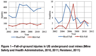
Primary roof support represents the first line of defence against rock-related falls of ground in underground mines, and improper utilization and/or understanding of primary supports applicability and behaviour can be costly and adversely affect rock-related safety. This is a major concern for underground mines, as roof support is the single most costly expense from a mining operations perspective and is the production bottleneck. This is further backed by the evidence that, in the USA, fatalities and hundreds of injuries still occur each year because of rib, roof, and massive roof falls, as shown in Figure 1 (Mark, Pappas, and Barczak, 2009).
Additionally, the fully-grouted passive rebar (FGPR), fully-grouted tension rebar (FGTR), and resin-assisted mechanical anchor bolts (RMABs), which constitute a large portion (89%) of the 68 million bolts installed each year in underground mines, can vary in cost quite dramatically. As a rough estimate, the FGPR is the least costly support, whereas the FGTR is roughly 10%, and the RMAB is around 29% greater than the FGPR. (Tadolini and Mazzoni, 2006; Spearing and Gadde, 2011).
To mitigate this concern a study was conducted in 2010, funded by the National Institute of Occupational Safety and Health and undertaken by Southern Illinois University of Carbondale and Peabody Energy, to assess the performance of primary roofbolts in underground coal mines in the USA for improved safety and cost. This was accomplished using underground roofbolt monitoring solutions, field data, and numerical modelling to better understand the quasi-static behaviour of underground coal mine roofs and the response behaviour of the bolts.
Furthermore, over 170 instrumented extensometers, closure meters, shear meters, fully-grouted passive rebar (FGPR), fully-grouted tension rebar (FGTR), and resin-assisted mechanical roofbolts (RMAB) were installed at three coal mines across the USA. Of these three mines, two used the room and pillar extraction method and the other used the longwall extraction method.
Mine sites
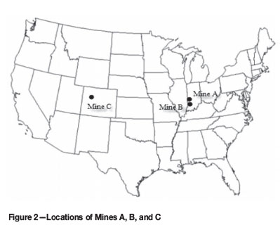
Three underground coal mines were selected for the project. The sites needed to have similar immediate rock lithology, and mine management needed to provide the equipment and labour to carefully install the expensive instrumented bolts on-cycle, which adversely affected mine productivity. The actual mine names are not disclosed, but they are referred to as mines A, B, and C hereafter. Mines A and B were both room and pillar coal operations located in southwestern Indiana, and Mine C was a longwall operation in northwestern Colorado (Figure 2).
In the following sections, the layout of the instrumentation sites at each mine site, the local geology of the instrumentation sites, and the instrumentation itself will be discussed.
Rockbolts and instrumentation
Rockbolts
The rockbolts were installed on-cycle with the production operations as primary support at both room-and-pillar mines. At the longwall mine, the rocksbolts were supplemental support because primary support had already been installed during panel development. Reiterating, the three bolt systems compared in this project were fully-grouted passive rebar (FGPR), fully-grouted tension rebar (FGTR), and resin-assisted mechanical roofbolts (RMAB). The FGPR is considered a passive support because it is not tensioned on installation, whereas the FGTR and RMAB are considered active because they are tensioned on installation. As the names suggest, FGPR and FGTR support are installed with full resin encapsulation, while the RMAB utilize an anchor at the back of the hole with a 1.22 m (4 ft) resin encapsulation.
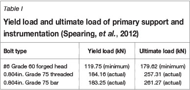
All three mines used no. 6 (19 mm or 0.75 inch nominal diameter) Grade 60 fully grouted passive rebar as their primary support; however, after slotting of the rebar, which is required for instrumenting the rockbolts, the residual yield capacity of the bolts was well below the requirements set out by the mines' ground control plans. Therefore a bolt with higher yield and ultimate capacity, (20 mm or 0.804 inch Grade 75 rebar) was chosen for the instrumented bolts. A comparison of the yield and ultimate load capacity of the no. 6 Grade 60 and 20 mm (0.804 inch) Grade 75 bolts is shown in Table I. All of the rockbolts, bolt plates, and resin were donated from the same manufacturer. This was to eliminate vendor-related variability of the materials.
Instrumentation
All past studies related to roofbolt monitoring have been conducted mainly through the National Institute of Occupational Safety and Health (NIOSH), by Signer from 1984-1997 (Serbousek and Signer, 1984; Signer, 1988; Signer, Franklin, Mark, and Hendon, 1993; Signer, Cox, and Johnston, 1997). For those studies the instrumented rockbolts were equipped with a short baselength (<25 mm) resistive foil strain gauges. The shortcoming of this technology was that only 10% coverage of the bolt was achieved due to the shortness of gauges. Additionally, the loadings that were obtained were highly localized and the entire axial loading profile of the bolts was not well represented.
In contrast to these past studies, a new technology was utilized in an attempt to better capture the axial loading profile of the rockbolts. For this, rockbolts were fitted with long baselength (200-500 mm) displacement sensors developed by YieldPoint Inc. This technology utilizes an array of sub-micrometre resolution displacement sensors that measure the displacement of the bolt. Collectively, the array of gauges provides an axial loading profile of the bolt over time. A more in-depth discussion of this technology is presented by Spearing et al. (2012), but overall, a greater coverage of the bolt is obtained (75%) as well as an averaged and more representative axial loading profile of the rockbolt.
Once the bolt type, capacity, and technology had been determined, the bolts were machined by slotting along their length for placement of the sensors (Figure 3). YieldPoint Inc. was chosen as the manufacturer because of their competitive costs, their willingness to be present during instrumentation installation at the mine sites, and because they were able to develop all of the rockbolt instrumentation, as well as closure meters, extensometer, tilt meters, and data loggers.
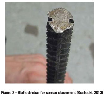
The bolts were slotted to a depth of 3.2 mm (0.126 inch) for placement of six 45.7 cm (18 inch) displacement sensors (three on each side). Six sensors per bolt were chosen to mitigate the total cost per bolt while still obtaining a comprehensive coverage of the bolt. The sensors were placed in an end-to-end arrangement within the machined slots and were held in place by epoxy.
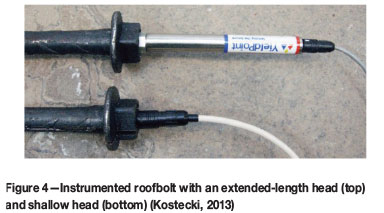
The electronics of the sensors were housed in an extended steel head at the end of the rockbolt. When data logging began, Mine A and Mine C utilized the extended bolt head shown in Figure 4. This bolt head protruded some length below the hangingwall; eventually, due to moving machinery at the face, mainly the continuous miner holing through the crosscuts, several instruments were knocked out and destroyed. Therefore a more adaptive shallow head (shown at the bottom of Figure 4) was used later at Mine B to eliminate this problem.
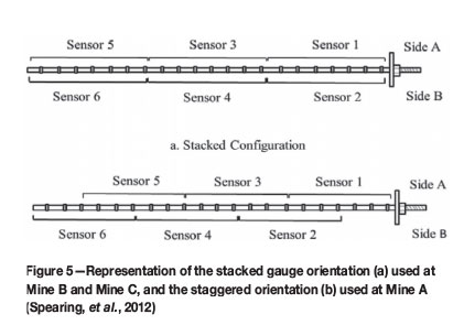
The sensors on the bolts were arranged in two configurations. Mines B and C utilized a stacked configuration shown in Figure 5a and Mine A utilized a staggered configuration shown in Figure 5b. For the stacked configuration the sensors are placed in a diametrically opposed pattern in the machined slots, and for the staggered configuration the sensors are offset by half the baselength of the sensor. It was felt that the stacked configuration could miss some of the localized shearing loads that could occur between the sensors, and a staggered arrangement was therefore considered for comparison purposes.
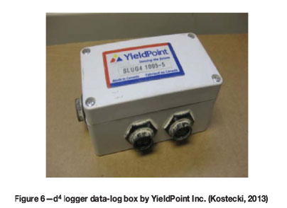
The data was collected using data loggers, shown in Figure 6. Each data box could store over 30 000 readings and was equipped with four channels (one per rockbolt) that were wired to the instruments. The data loggers were manually set to take readings every hour, which could then be retrieved via a USB connection and custom software also developed by YieldPoint. Routine visits to the instrumentation site were scheduled to download the data. The data, which was recorded in microstrain, was then manipulated to obtain axial load, axial strain, and axial stretch. A conversion factor of 153 µ-strain per ton was used, based upon the cross-sectional area of the machined rebar and the elastic modulus of the bolt steel.
Instrumentation sites and local geology
The selection of the instrumentation sites was vital to the overall scope of this project. There were nine instrumentation sites in total - one for each of the three roofbolt systems (i.e. FGPR, FGTR, RMAB) for each of the mines. The local geology was investigated by a consulting geologist (Padgett, 2010).
Mine A
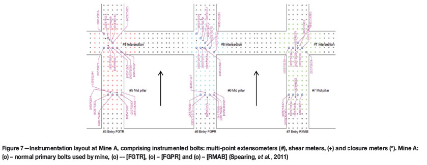
Instruments at Mine A were installed as primary support oncycle. Figure 7 shows the instrumentation sites. From left to right in Figure 7 the entries were numbered 5, 6, and 7. These entries were chosen for several reasons. First, instruments were placed in three adjacent entries so that the geology was as similar as possible. Next, the adjacent entry to no. 5 was a belt entry and the adjacent entry to no. 7 was a return-air entry blocked off by a stopping. Finally, because monitoring of the instruments was to last several months, these entries were located in an area such that production would not be hindered over the entire monitoring period.
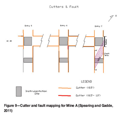
Instrumented roofbolts were installed in the intersections and mid-pillar regions of each entry. The arrows in Figure 7 show the direction in which the face was advancing during instrument installation, and therefore the mid-pillar was mined first and the mid-pillar instruments were installed a few days prior to the intersection instruments. The patterns at each site were identical. The diagonal pattern shown across the intersections was of particular importance as this represents the longest span, and therefore would offer the greatest chance of capturing the highest displacements and loadings over time. The FGTR instrumented bolts were installed in entry 5, FGPR in entry 6, and RMAB in entry 7. The non-instrumented support surrounding each test site, shown in Figure 7, was of the same type as the instrumented support in each area. Most importantly, each instrumented bolt was zeroed prior to instrumentation using a d-READER instrument reader provided by YieldPoint Inc. The entries were 6.1 m (20 ft) wide with 24.3 x 24.3 m (80 x 80 ft) centre-to-centre pillars (Spearing, et al., 2011).
Two extensometers were installed at each intersection and one in the mid-pillar. The extensometers were anchored 3.66 m (12 ft) into the roof to measure differential movements. Two tilt-meters (shear meters) were installed in each entry, one in the mid-pillar and one in the intersection. Finally, closure meters were placed at each mid-pillar and intersection (Kostecki, 2013).
Each instrument was given an individual identification number to describe the instrument type (i.e. extensometer, closure, tilt, rockbolt) and the mine location. For example, the centre instrumented bolt in the intersection of the no. 5 entry is 100575023. In this case the first 5 denotes the mine site (in this case Mine A). The 7 denotes the instrument type (in this case an instrumented rockbolt) and finally, the 5023 denotes the unique instrument identification number. A similar nomenclature is followed for remaining instruments, except the 7 is replaced by a 9 for extensometers, 13 for tiltmeters, and a 2 for closure meters.
Mine A local geology
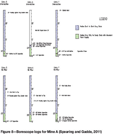
Mine A is located in southwestern Indiana and exploits the Danville No. 7 seam of the Dugger Formation. Borescopes to 4.27 m (14 ft) above the coal seam were taken at each instrument site and the roof lithology is shown in Figure 8. In the immediate roof, the first 0.7 m (2.3 ft) on average was a medium-grey silty shale. This was overlain by a medium dark gray shale to the top of the 4.26 m (14 ft) borescope. Hairline separations were present in the bottom 0.3 m (1 ft) of the immediate roof in entries no. 5 and no. 7, with the most discernible separation in the no. 7 mid-pillar, where a 6.35 mm (0.25 inch) -45° hairline separation existed. Within the no. 6 entry, hairline separations existed from the 0.61-0.91 m (2-3 ft) level. The immediate floor was a soft medium-grey claystone common to Illinois Basin Mines. The coal seam thickness was 1.34 m (4.4 ft), on average, and was relatively flat-lying. The average mine height was 2.29 m (7.5 ft) with an overburden of 97.5 m (320 ft).
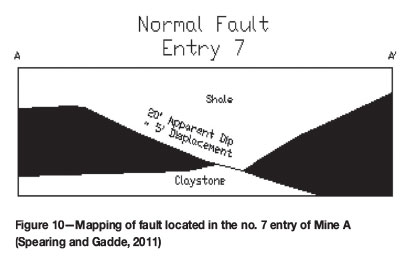
Cutters existed throughout the mine site, shown in Figure 9, along most of the entries and crosscuts. The most significant was a 15.2-30.5 cm (0.5-1.0 ft) cutter at the eastern corner of the no. 6 intersection. A normal fault also existed in the no. 7 entry. This was not discovered until after the instruments had been installed and was not intended as part of the project design. The normal fault had a strike in the N10°W direction with a dip of 20° and a throw of 5 ft, which completely displaced the coal seam. A diagram of the normal fault is shown in Figure 10.
Mine B
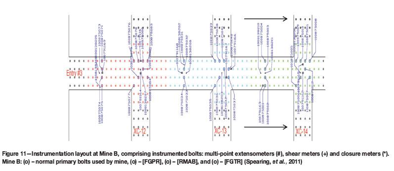
Instruments at Mine B were installed as primary support oncycle. The instruments were all installed in the same entry (i.e. entry 3 - Figure 11). This was mainly because of ventilation issues at the mine, and limited access to the adjacent entries at the time of installation. Parallel entries similar to Mine A were initially designed for.
Instrumented roofbolts were again installed in the intersections and mid-pillars regions. The arrows in Figure 11 show the direction in which the face was advancing during instrument installation. The FGPR instrumented bolts are denoted by the red circles up to crosscut 12 in Figure 11, RMAB are blue up to crosscut 13, and the FGTR are green up to crosscut 14. The non-instrumented support surrounding each test site was of the same type as the instrumented support, and each instrument was zeroed prior to instrumentation.
Two extensometers were installed at each intersection and one in the mid-pillar, as well as tiltmeters and closure meters. The instrument identification numbers follow the same scheme as previously discussed for Mine A. The entries were 5.5 m (18 ft) wide with 22.9 x 22.9 m (75 x 75 ft) centre-to-centre pillars (Spearing, et al., 2011).
Mine B local geology
Mine B is also located in southwestern Indiana, and exploits the Springfield No. 5 coal seam of the Petersburg Formation. The depth to the instrument site was 106.7 m (350 ft) on average. Borescopes were taken at Mine B as at Mine A, although only four borescopes were obtained in total. The lithology for Mine B is shown in Figure 12.
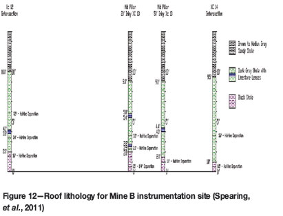
The immediate roof comprised a black shale in the first 0.6 1m (2 ft) overlain by a dark grey shale with limestone lenses up to 3.05 m (10 ft) in the most extreme case. This was overlain with a brown to medium grey sandy shale up to the top of the 4.27 m (14 ft) borescope. Hairline separations were found from 0.15 m (0.5 ft) up to almost 1.83 m (6 ft). The area was again underlain by weak underclay.
Mine C
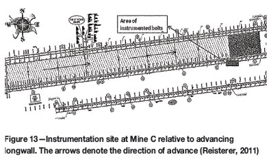
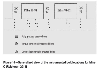
Instruments at Mine C were installed as supplemental support. Figures 13-17 show the instrumentation sites. The gate roads were already developed and had been supported with primary and secondary support. The instrumented supports were installed in the mid-pillar and intersections and were all located in the same entry. The FGPR bolts were installed in the no. 86 crosscut and mid-pillar, the FGTR bolts were installed in the no. 84 crosscut and mid-pillar, and RMAB bolts were installed in the no. 82 mid-pillar and crosscut. The direction of advance of the longwall is shown in Figure 13.
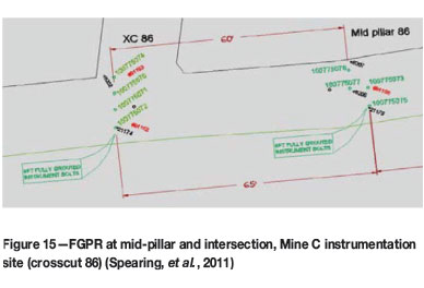
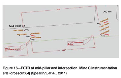
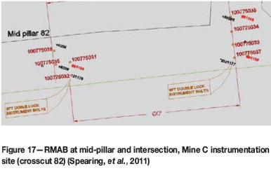
Two extensometers were installed at each intersection and one in the mid-pillar, as well as tiltmeters and closure meters. The instrument identification numbers followed the same scheme as previously discussed. The gate road was 5.8 m (19 ft) wide with 41.1 x 61.0 m (135 x 200 ft) abutment pillars at a depth of 366 m (1200 ft) (Spearing, et al., 2011).
The primary support at the mine consisted of FGPR bolts spaced at 1.52 m x 1.52 m (5 x 5 ft) spacing along and across the entry, with wire mesh. The secondary support used a similar bolting pattern but added steel straps between the previously installed primary supports. The tailgate support also included 22 inch (56 cm) metal cans or cribbing at 3.05 m (10 ft) intervals (Reisterer, 2011). All in all, the tailgate was very well supported prior to and after installation of the instrumentation.
Mine C local geology
Mine C is a longwall coal mine located in Colorado and exploits the Wadge coal seam. Borescopes were conducted at Mine C as at mines A and B. The lithology for Mine C is shown in Figure 18.
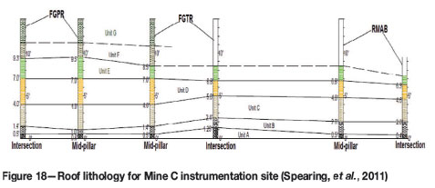
The immediate roof consisted of broken shale (Unit A) in the first 0.19 m (0.625 ft) on average. This was overlain by shale (Unit B) up to 0.52 m (1.7 ft) on average. Interbedded sandstone and shale (Unit C) overlaid the shale up to 1.52 m (5.0 ft) in the most extreme case. Sandstone with minor shale interbeds (Unit D) constituted the region 2.59-2.89 m (8.5-9.5 ft). Above this region were interbedded shale and sandstone (Unit E), sandstone and shale (Unit F), and shale (Unit G). Water ingress was also noticed within Unit F and Unit E during scoping (Figure 18).
Results and discussion
As described earlier, the data loggers were set to extract readings from the instruments at hourly intervals. These readings were then downloaded to the computer during regular visits to the mine every two to four weeks. Since there were a total of 170 instruments, the data obtained was extensive. For instance, for Mine A alone over 200 000 individual readings were taken from the instrumented bolts. Detailed analysis all of this data is out of the scope of this paper. Several papers have already been published containing a detailed discussion of results from each mine (Spearing and Gadde, 2011; Spearing, et al., 2011; Reisterer, 2011; Ray, Gadde, and Spearing; 2012; Kostecki, 2013). This paper reports and comments on only the broadest findings.
Initial bolt loads
As mentioned previously, the data was obtained using the YieldPoint d4 data-loggers. Unfortunately, these data-loggers were not intrinsically safe (i.e. not rated for use in potentially explosive atmospheres) and therefore were not permitted by MSHA law to operate until fresh air had been established in the entries. This caused a significant delay (6-10 days) in the initial bolt readings for mines A and B and a short delay (1-2 days) for Mine C (Spearing, et al., 2011).
The earliest bolt readings are shown in Figure 19, which represents an average of all the initial bolt readings from each bolt type (FGPR, FGTR, and RMAB) from each mine (A, B, and C).
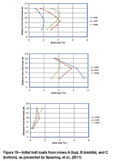
The initial assumption was that the active bolts would show a few tons more load on installation than the passive bolts, as they are tensioned on installation (4-5 t versus 1-21), especially since the roofbolter was set to 325 footpounds (441 Nm) torque (Kostecki, 2013). However, the results showed that the initial loads on the bolts were not significantly different. Although the results may be a poor representation of the initial loads at mines A and B, because of the delay in readings, the readings at Mine C were obtained soon after installation, and yet there was no significant difference in loadings.
Table II displays a more intuitive representation of the average bolt loads per system and per mine. From this table it can be shown that the time delay for the first readings at mines A and B had a significant effect on the loadings overall, as some mining-induced loadings had occurred. More importantly though, Table II captures little difference in loadings between the bolt systems, as the FGPR averaged 2.68 t, FGTR 2.71 t, and the RMAB 2.62 t. Several mechanisms have been proposed to account for the lack of difference in loadings:
► The first mechanism, which was proposed by Spearing et al. (2011), is that when upthrust from the bolter is applied to the bolt during installation a significant reduction in tension on the active bolts can be lost, as opposed to active bolts installed with zero thrust. This can be further justified by observing the bolts at Mine C. Although only the averages of all the bolts at Mine C are shown in Figure 19, some individual bolt readings showed negative axial tension. This was not observed at mines A and B, probably because of the delay in obtaining the initial readings, and enough time had passed for mining-induced loadings to the bolts. This behaviour has also been observed by several other researchers (Karabin and Debevec, 1976; Mahyera Kempen, Conway, and Jones, 1981; Mazzoni, Karabin, and Cybulski, 1981)
► Another likely reason could be resin creep occurring soon after installation. This would be particularly evident in the active bolts, as very small displacements could result in the load loss of the bolts.
Overall, no significant difference was found in the initial loading phase at all three mines. Additionally, more detailed statistical analysis found that there was no significant difference in loadings over time either (Kostecki, 2013). In particular, Kostecki (2013) observed that, for the instrumented bolts in this study, if 70% of the bolt yield was assumed to be applied during bolt tensioning, then only 0.156 inches of bolt displacement would be needed to either retain or lose tension. Seventy per cent of the bolt yield was chosen because the torque-to-tension ratio was not known for the bolts and this was the recommended value given by a leading bolt manufacturer. Considering this, it was determined that when bolts are installed where the immediate roof is prone to weathering, such as the case at Mine A, this small amount of displacement could 'release' the tension in the active bolts over time - that is, if the load was not already lost soon after installation. A similar observation was made by Unrug, Padgett, and Campoli (2004).
Modelling
Fast Lagrangian Analysis of Continua FLAC3D (Itasca, 2010) was utilized in an attempt to calibrate a numerical model to the bolt loadings obtained from all three mines. The results from all three mines and bolts systems were generally the same, therefore only results from the passive (FGPR) bolts at Mine A will be discussed.
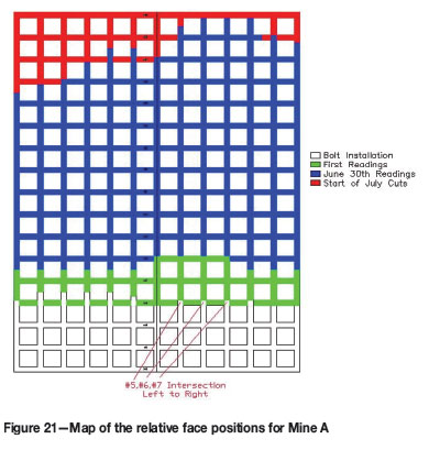
The roof lithology (Figure 8) and the floor lithology for Mine A were generated into a global grid, shown in Figure 20. This represented a portion of an entire panel at Mine A. The objective was to simulate the mining-induced loadings generated in the bolts as the panel progressed to two points in time - when the first readings were acquired and the readings at the beginning of the next month. These two points and times correspond to the relative face positions shown in Figure 21. Also shown in Figure 21 are the locations of the no. 5, 6, and 7 entries where the FGTR, FGPR, and RMAB were installed.
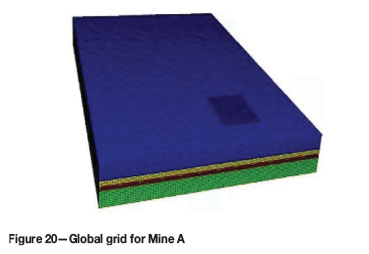
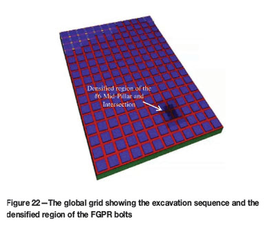
The panel was a large region, therefore to limit the model run-time, the zones were kept relatively large throughout (10 x 10 ft; 3.05 x 3.05 m), except in the area of interest. In this case the no. 6 mid-pillar and intersection were of interest because this was the location of the passive instrumented bolts. Therefore the zone sizes were 'densified' via a FISH subroutine, which broke the zones down into smaller 0.3 m x 0.3 m (1 x 1 ft) zones. An excavation sequence, which made a 12.2 m (40 ft) cut of coal and then placed a pattern of bolts, was then modelled. The excavation sequence progressed until the face positions were matched to those shown in Figure 21. At this point the loads on the instrumented bolts were extracted from the model and processed in a similar manner as the actual instrumented bolt data. Figure 22 shows the same global grid as in Figure 20 with the lithology above the coal pillars removed to show the excavations generated. In the case of Figure 22, the face positions match the exact face position of the 'Start of July Cuts' shown in Figure 21. Also shown is the densified no. 6 mid-pillar and intersection where the FGPR bolts were located. The model was assumed to undergo elastic-perfectly plastic behaviour and followed the Mohr-Coulomb failure criteria.
Bolts 100575073 and 100575074 were arbitrarily chosen for discussion because they best represent the challenges still remaining in the modelling portion of this study. The actual results from the instrumented bolts at two points in time (i.e. First Scan Actual and June 30 Actual) and the results of an elastic-perfectly plastic Mohr Coulomb model at two points during the excavation (i.e. First Scan Plastic and June 30 Plastic) are shown in Figure 23. The actual bolt loadings of the FGPR bolts tend to show peak loadings nearest to the excavation hangingwall, shown by point A in Figure 23. This was to be expected, as over time FGPR bolts are loaded by the downward movement of rock, which should transfer down the length of the rebar to the head of bolt. For the modelled bolts, the peak loadings tend to be somewhat near the head of the bolt but not nearly as distinctly as the actual loadings. Additionally, the modelled loads tend to be generally lower and less pronounced with no real peaks in loading, as is the case for bolt 100575074 (point B of Figure 23). In the actual bolts, the peaks are generated because of some discontinuity driving the loading at that point (e.g. dilation or shearing of the strata). For example, from point A in Figure 23, it is unclear what phenomena are driving this peak load, but these peak loadings were not re-created within the model.
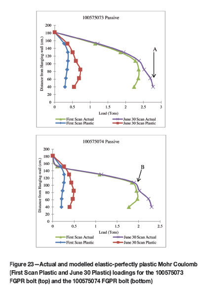
It was therefore concluded that although the modelling shows potential to recreate the in situ loadings, challenges still remain. A particular challenge is replication of the bearing plate at the head of the bolt, which could be the reason behind the lack of peak modelled loads nearest to the hangingwall. Challenges also remain in modelling the geological structure on a local scale. For instance, dilation and shearing of the immediate roof over time could account for the absence of peak loadings shown by point B in Figure 23.
Conclusions
After comparison of the in situ data of the three most popular primary roofbolt systems, there was no evidence to indicate a difference in performance of the active primary roofbolts versus the passive primary roofbolts on any of the three mines. Additionally, in the initial loading phase, the active bolts showed no difference in loading, indicating that tension bleed-off is more of a concern than originally thought. For the initial computer modelling studies, of replicating in situ primary roofbolt loading mechanisms, challenges still remain in obtaining a good match and replicating the discontinuous roof rock and in situ bolt behaviour over time. In particular, simulation of the bolt bearing plate and the recreation of the geological structure seem to be the greatest challenges at this time. This reinforces the idea that in situ measurements are still needed for design and to improve current support practices. The in situ monitoring technology from YieldPoint worked well over the entire monitoring period. The increased coverage of the long baselength displacement sensor technology improves measurement of the overall load profile of the rockbolts. Due to the length of the long baselength sensors, and the end-to-end arrangement of sensors, a more averaged loading profile is obtained at the expense of localized loads captured by short baselength strain gauges used by previous in situ bolt studies.
Acknowledgements
The funding and support provided by NIOSH (under BAA number 2008-N-10989) is greatly acknowledged, as well as the considerable support given by Peabody Energy. Special thanks to Jennmar Corporation, Minova USA, and Dr A.J. Hyett from YieldPoint Inc. for providing the instrumentation for the project and for their assistance during the instrumentation installation.
References
Itasca Consulting Group, Inc. 2010. Fast Lagrangian Analysis of Continua in 3 Dimensions, version 4.0. Minneapolis, MN. [ Links ]
Kostecki, T. 2013. The instrumentation of primary roof bolts in a room-and-pillar mine and the modeling of their performance. Master's thesis, Southern Illinois University Carbondale, Carbondale, IL. [ Links ]
Karabin, G J. and Debevec, W.J. 1976. Comparative evaluation of conventional and resin bolting systems. Informational Report 1003. Mine Enforcement and Safety Administration, Arlington, VA. [ Links ]
Mahyera, A., Kempen, C.J.H.B., Conway, H.P., and Jones, A.H. 1981. Controlled thrust and torque placement of mechanical anchor bolts and their relationship to improved roof control. Proceedings of the 1st International Conference on Ground Control in Mining, Morgantown, WV. pp. 98-105. [ Links ]
Mazzoni, R.A., Karabin, G.J., and NS Cybulski, J.A. 1981. A trouble-shooting guide for roof support systems. Informational Report 1237. Mine Safety and Health Administration, Arlington, VA. [ Links ].
Mark, C., Pappas, D.M., and Barczak T.M. 2009. Current trends in reducing groundfall accidents in U.S. coal mines. Proceedings of the SME Annual Meeting and Exhibit. Society for Mining, Metallurgy, and Exploration, Inc., Littleton, CO. pp. 1-5. [ Links ]
Mine Safety and Health Administration. 2012. Injury experience in coal mining, 2010. (IR 1354). Department of Labor, Assistant Secretary for Mine Safety and Health. http://www.msha.gov/Stats/Part50/Yearly%20IR%27s/2010/ Coal%20Mining%202010.pdf [ Links ]
Mine Safety and Health Administration. 2012. Injury experience in coal mining, 2011. Informational Report 1359. Department of Labor, Assistant Secretary for Mine Safety and Health. http://www.msha.gov/Stats/Part50/Yearly IR's/2011/Coal Injury Experience-2011.pdf [ Links ]
Padgett, J. 2010. Personal communication (private consulting geologist). [ Links ]
Ray, A., Gadde, M., and Spearing, A.J.S. 2012. Comparison of the performance of active and passive roof bolts in an Illinois Basin coal mine. Proceedings of the 31st International Conference on Ground Control in Mining. West Virginia University, Morgantown, West Virginia. [ Links ]
Reisterer, J.R. 2011. The interaction of active or passive roof bolts, stress conditions, and the immediate roof strata in a longwall mine in the United States. Master's thesis, Southern Illinois University Carbondale, Carbondale, IL. [ Links ]
Serbousek, M.O. and Signer, S.P. 1984. Load transfer mechanics in fully-grouted roof bolts. Proceedings of the 4th International Conference on Ground Control in Mining. West Virginia University, Morgantown, WV. pp 32-40. [ Links ]
Signer, S. 1988. Comparative studies in the mechanics of grouted roof bolts. Proceedings of the 7th International Conference on Ground Control in Mining. West Virginia University, Morgantown, WV. pp 282-288. [ Links ]
Signer, S.P., Cox, D.J., and Johnston J.L. 1997. A method for the selection of rock support based on bolt loading measurements. Proceedings of the 16th International Conference on Ground Control in Mining. West Virginia University, Morgantown, WV. pp. 183-190. [ Links ]
Signer, S.P., Franklin, G., Mark, C., and Hendon, G. 1993. Comparison of active versus passive bolts in a bedded mine roof. Proceedings of the 12th Conference on Ground Control in Mining. Lakeview Resort and Conference Center, Morgantown, WV. pp. 16-23. [ Links ]
Spearing, A.J.S. and Gadde, M.M. 2011. Final report on NISOH funded project Improving underground safety by understanding the interaction between primary rock bolts and the immediate roof strata. NIOSH Project, BAA no. 2008-N-10989. National Institute for Occupational Safety and Health, Atlanta, GA. [ Links ]
Spearing, A.J.S., Gadde, M., Ray, A., and Lee, S. 2011. The initial performance of commonly used primary support on US coal mines. Proceedings of the 30th International Conference on Ground Control in Mining. Lakeview Scanticon Resort & Conference Center, Morgantown, WV, 26-28 July. [ Links ]
Spearing, A.J.S., Hyett, A.J., Kostecki, T., and Gadde, M. 2012. New technology for measuring the in- situ performance of rock bolts. International Journal of Rock Mechanics and Mining Sciences, vol. 57. pp. 153-166. doi: 10.1016/j.ijrmms.2012.07.027 [ Links ]
Tadolini, S.C. and Mazzoni, R.A. 2006. Twenty-four conferences: more than one-hundred seventy papers; understanding roof bolt selection and design still remains priceless. Proceedings of the 25th International Conference on Ground Control in Mining. Lakeview Scanticon Resort & Conference Center, Morgantown, WV. pp. 382-389. [ Links ]
Unrug, K., Padgeet, P., and Campoli, A. 2004. Coal mine primary support selection: tension versus non-tensioned roof bolt systems. Proceedings of the 23rd International Conference on Ground Control in Mining. Lakeview Scanticon Resort & Conference Center, Morgantown, WV. pp. 258-263. [ Links ]
This paper was first presented at the, 6th Southern African Rock Engineering Symposium SARES 2014, 12–14 May 2014, Misty Hills Country Hotel and Conference Centre, Cradle of Humankind, Muldersdrift.

