


Services on Demand
Article
 English (pdf)
 Article in xml format
 Article references
Indicators

Related links
-
 Cited by Google
 -
 Similars in Google
Share

 Permalink
Journal of the Southern African Institute of Mining and Metallurgy
On-line version ISSN 2411-9717
Print version ISSN 2225-6253
J. S. Afr. Inst. Min. Metall. vol.114 n.1 Johannesburg Jan. 2014
SAMPLING AND ANALYSIS PAPERS
An overview of sampling best practice in African mining
I.C. SpangenbergI; R.C.A. MinnittII
IContinental Africa Region, AngloGold Ashanti Ltd, Johannesburg, South Africa
IISchool of Mining Engineering, University of the Witwatersrand Johannesburg, South Africa
SYNOPSIS
The status of sampling practices in the gold mining industry in Africa was determined as an initial step in a process to standardize sampling practices in the mining industry. Twenty-one gold mines, twenty metallurgical plants, and thirteen laboratories were rated for the potential influence of the relevant sampling errors on each component of the particular sampling system. The findings of the study on the status of equipment, standards, procedures, and management principles were presented in a dissertation (Spangenberg, 20121) and are now used by AngloGold Ashanti's mines in the quest for correct sampling practices. The information is also used to compile a guideline on leading practice procedures for sampling methods in gold mining. This article is an overview of sampling best practice found in African mining
Keywords: theory of sampling, best practise, sampling errors, sampling standards.
Introduction
In a keynote address at the Sampling 2008 conference in Perth, Frangois-Bongarçon (2008) stated that the modern sampling theory (the Theory of Sampling - TOS) is enjoying its golden age, sixty years after its inception and after alternate periods of acceptance and rejection by the industry. Pollard et al. (2009) explained that, from their experience in industry, education, training, and professional development, the minerals industry regards sampling as an important part of its operations, but often does not recognize the differences between good and bad sampling practices. Poor understanding of sampling theory and how it should be applied, a corporate cost-saving culture, especially concerning technical issues that are not well understood by executive management, and a failure in the education of industry profes- sionals to develop an understanding of the fundamentals and economic importance of good sampling practice, were listed as reasons for this.
A growing understanding and appreciation of sampling theory and methods has led to a new era in which mining companies are in fact implementing new sampling procedures and protocols. A comprehensive international sampling standard for the mining industry does not exist, but Minnitt (2007) suggested that standardization through the identification of structural problems and continuous improvement of sampling processes should be instituted at a national level in the interests of optimal development of the national patrimony.
Where necessary the principles of TOS are referred to in the body of the paper. The total sampling error (TSE) is the sum of all sampling variances contributed by the errors and bias-generating components in a sampling protocol. Contrary to the popular belief that the errors will 'average out', sampling errors are additive and not self-compensating. Gy (1979) subdivided the errors involved in sampling into seven different classes without distinguishing between accuracy, precision of measurement, or the natural variability of the material being sampled. Although eleven sources of sampling error have been identified not all the errors were named by Gy (1979); however, he did identify them in his writings. The sampling errors that contribute to the non-representativeness of samples were described by Holmes, (2009) and Pitard (2005, 2006), and are presented in Table I. The sampling errors are grouped according to the factors having the largest effect on them.
The aim of this paper is to document the current sampling practice at a number of gold mines throughout Africa and develop a system and standards for sampling practice at such operations. To this end twenty-one gold mines, twenty metallurgical plants, and thirteen laboratories were visited to rate the potential influence of the relevant sampling errors on each component of the particular sampling system. The general commitment of each of the mining operations mentioned in the thesis by Spangenberg (2012), to best sampling practice at each stage of mineral development, is described in this paper. The stages include exploration, mining, broken ore sampling of materials on their way to the plant, metallurgical plant sampling, and sampling in the analytical laboratories. The response of management to issues related to sampling problems is also considered. This article concentrates on sampling practices only and conclusions are drawn to establish best practice.
Exploration sampling
The concept of 'correct' sampling has to be linked to the concept of the 'lot', used here to refer to a mass of material from which a representative sample is to be extracted. A sample can be referred to as 'correct' only if each and every fragment in the lot has the same statistical chance as every other fragment of being in the sample. The term 'sampling dimensions of the lot' therefore refers to the way in which the material is presented to the sampling equipment, and implied in that is the notion that the resultant sample will be correct or not. A three-dimensional lot, such as a large stockpile or waste dump, is the worst possible lot shape from which to extract a sample simply because the bulk of the lot is not accessible to the sampling equipment, and can therefore never yield a correct and therefore representative sample. An example of a two-dimensional lot is typically that of a large area of a slimes dam which has to be sampled, the only reasonable way being to use an auger or reverse-circulation (RC) rig to recover the material from the drill-hole. Although the sample can never be truly representative of the lot, because it can never be correct, this is the best we can do without totally reclaiming the slimes dam and re-stacking it. The best presentation of a lot is in a one-dimensional form, where the material is presented to the sampling equipment, in this case a cross-stream or cross-belt cutter, as a single stream flowing off the end of a conveyor belt. Although constraints on the sampling dimensions of the lot mean that diamond drilling cannot obey the basic rule for correct sampling, because the lot is defined in two dimensions and the samples are extracted across the third dimension, drilling is the only available means of obtaining estimates of the grade at a given locality. This is true at the exploration stage, in open-pit and underground mining operations, and in the case where the grade of waste dumps, tailings dams, or other three-dimensional lots is required (Holmes, 2009).
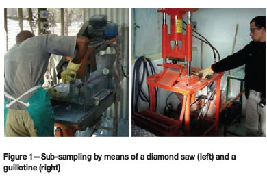
Diamond drilling is the primary sampling method employed at the mines that have exploration programmes, with shallow depth drilling programmes being undertaken with RC drilling. Secondary sub-sampling of borehole core is by splitting the core using either manually operated diamond saws, more advanced semi-automatic units, or by guillotine-type splitters as shown in Figure 1. Guillotine-type splitters have been used in the past but in the interests of better representation have generally been replaced by diamond saws. The chisel-type core splitter produces an imperfect split and causes sample loss.
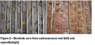
Cores from some reef types, for example Carbon Leader reef or saprolite materials, have been known to disintegrate during splitting of sub-samples, as shown in Figure 2. Splitting borehole core by means of a diamond saw is relatively easy but sub-sampling of broken core is open to subjective selection by the geologist. In some cases it is better to pulverize a complete increment of core before splitting.
The so-called in situ nugget effect (INE) is believed by some to have significant influence on the results of sampling of borehole core recovered from exploration drilling. The INE is considered by Pitard (2009) to be characteristic of the reef, and that the only way to improve the results from sampling is to attempt to reduce the effect by drilling larger diameter boreholes.
Elaborate exploration diamond drilling techniques, including multi-tube wireline core retrieval systems, were developed by Boart Longyear™ (2011) in 1958. These consist of an inner tube group, which collects the core sample during the drilling process and is independent of the outer tube group, to extract core in difficult conditions. Such core retrieval methods aid in reducing the influence of the IDE and IEE. The FSE would take effect only once the core is broken or pulverized, and it would have to be managed by ensuring that the core is reduced to the correct fragment size and mass before a sample is extracted. The potential influence of the IPE is moderate when handling solid borehole cores and high if the core is fragmented when it is recovered from the drill. Francois-Bongarçon (2011) is firmly of the opinion that none of the errors mentioned above are relevant at the stage of sampling borehole core or collecting face chip samples from an underground stope. Instead, he and Lyman (2011) believe that retrieving channel samples and borehole core samples could be referred to as 'simply taking a measurement' rather than taking a sample per se. In their opinion it is only once the core is broken that sampling errors and bias will be incurred.
Allocations of capital expenditure based on the analytical results from exploration samples are usually large, making it imperative that suitable equipment be employed to recover the largest diameter intersections of the reef that are practically possible. Diamond saws or the automatic core saw such as that developed by Almonte Diamond Pty Ltd (2011) should be used to split the core, while broken or brittle core should be pulverized before splitting.
Sampling in mining operations
Open-pit grade control sampling
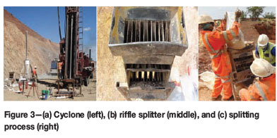
RC drilling is the preferred primary sampling method in open-pit mining operations. Once the broken RC drill cuttings are recovered, several methods of secondary sampling are used. RC rigs are usually accompanied by a cyclone (Figure 3a) which is used to collect the borehole cuttings, usually at 1 m intervals. Although the three-tier riffle splitter which is used to reduce the sample volume can be found at many mining operations, these items of equipment (Figure 3b) are usually flawed. Usually the splitters have been welded together such that the riffles lie immediately over one another, which results in the sub-samples being biased. Multi-stage splitters are also biased by design as the sub-sample from the same side is always selected for splitting in the next step (Figure 3c). Furthermore, failure to feed the cuttings evenly into the riffle splitter also introduces a bias.
A variety of mass reduction sub-sampling equipment is to be found at different mining sites, but these are generally characterized by inherent imperfections and should be avoided where possible. Such equipment includes:
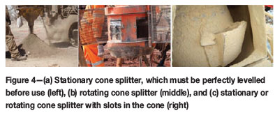
►Stationary cone splitters such as that shown in Figure 4a (left) with stationary collectors, where the cone has to be level to prevent the possibility of preferential sampling. Rotating collectors as shown in Figures 4c (right) work well in taking representative samples when the levelling is imperfect
►Rotating cone splitters (Figure 4b), should be avoided because the rotating cone imparts momentum, in addition to gravitational forces, to the sampled material, resulting in complex and uncontrollable flow mechanics that produces a biased sample
►Stationary or rotating cone splitters with slots in the cone as shown in Figure 4c (right) produce biased subsamples and should be avoided for the reasons given above.
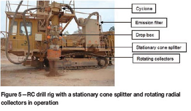
Decisions arising from the analysis of grade control samples usually involve immediate- to short-term mining decisions that direct the broken rock to the metallurgical plant, to a marginal ore rock dump, or the waste dump. RC drilling, rather than blasthole percussion drilling, should be used for primary grade control sampling. While the dangers associated with stationary cone splitters have been emphasized, splitters with rotating radial collectors should indeed be used for secondary or sub-sampling. The drill rig should be equipped with with a cyclone, a drop box, and an emission filter as shown in Figure 5. Sandvik Mining and Construction (2008) have developed and patented such a unit, the RotaPort™ cone splitter, which is functional in wet and dry conditions. Material that hinders sub-sampling should be collected per increment via the cyclone and sun-dried before splitting by means of a riffle splitter.
Underground grade control sampling
Pitard (2009) is of the firm belief that the INE, IDE, IEE, and IPE will influence chip sampling, which is used for underground grade control and selective mining. Harsh underground environmental conditions that include working in a confined space, as well as extreme heat and humidity, make it difficult for the sampler to firstly define and secondly extract a correct sample. Heat and humidity contribute to the exhaustion of the sampler. The samples are collected from advancing stope faces, which are farthest away from the shaft. On arrival at the area to be sampled, the sampler has to ensure that the work area is safe from possible falling rocks and methane. Samples are measured off along the stope at specified intervals and marked on the face. Extracting the marked sample by chipping an exact rectangle from the solid rock face and ensuring at the same time that all the rock fragments are collected, is a laborious process. Recent studies (Prinsloo, 2012) have shown that the samples collected are either incomplete or over-chipped. The INE is aggravated as the measured gold grade will be biased if the extracted sample is incomplete or over-chipped.
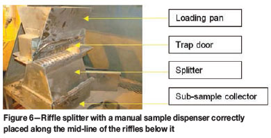
In cases where large numbers of sizeable primary underground chip samples have to be split using a riffle splitter the potential for IPE is high. Where there are insufficient riffle splitters to complete the tasks in the allocated time the samplers become careless and simply pass the sample through the splitter directly from the bag, leading to spillage and the discard of rock chips that do not pass through the riffles. The design of the splitter shown in Figure 6 is correct in that the trapdoor of the loading pan opens from the centre line and the sub-samples in this case are unbiased if the correct procedures are followed.
Growing awareness of the TOS has meant that many projects have been initiated at both surface and underground mining operations to find ways of eliminating the sources of bias that contribute to the IDE, IEE, IPE, and IWE. In particular the discrepancies in grade that occur between the shaft and the plant and lead to unacceptable mine call factors have been targeted for investigation.
The AngloGold Ashanti standard for underground chip sampling compiled by Kelly (2006), and revised by Flitton (2009), contains the basic principles for cutting acceptable channel samples. The standard lists the requirements for good sampling practice as follows:
►Sample area to be thoroughly clean. All pieces of loose rock to be removed from the sampling area. Fines and mud should be washed away with clean water
►Identification of individual reef components and demarcation of sample areas. The reef must be separated into different units based on its apparent quality and geological differences. Sample widths should not be less than 5 cm on thin carbon reefs and 7 cm on conglomerates, but less than 20 cm. A waterproof crayon should be used and sharpened frequently so that all lines are thin and clear. Each pair of lines delimiting the width and length of a sample must be parallel and drawn using a clino-rule. The lines demarcating the width of the sample are drawn parallel to the reef-waste contact while those demarcating the length of the sample are drawn at right angles to the reef-waste contact and should be marked out 10 cm apart. The sample width should include 2 cm of waste rock on either side of the reef band to ensure that the full width of the reef is chipped and any enrichment on the reef-waste contacts is included in the sample
►Measurement of sample widths. This entails the diligent measurement of sample widths to ensure an accurate gold value calculation in cm.g/t. The width of a reef is the shortest distance between the waste rock on each side, i.e. at a right angle to the reef band
►Chipping of samples refers to the prescribed method for actual sample collection. The demarcated area must be chipped to a uniform depth of 2 cm. The moil should be sharp to ensure cutting of the rock and to prevent 'powdering' by means of a blunt edge. The sample dish should be held immediately below the sample being chipped. The cutting edge of the moil should be covered while chipping is in progress to ensure that the rock chips are directed into the dish. All equipment should be cleaned after each sample taken to prevent cross-contamination
►Delivery of samples. Once chipping of the sample is completed it should be meticulously transferred to the sample bag to eliminate loss and contamination. Sample bags must be securely packed for transport from the working place and eventually to surface
►The operators should be motivated, trained, and encouraged to maintain a high standard in sampling practice
►Certified reference material (CRM) and blanks should be inserted in batches of samples.
This standard for underground chip sampling also discusses poor sampling practices such as contamination, sample loss, and fraud, and is based on principles described by Sichel (1947), Storrar (1987), and Cawood (2003).
Broken ore sampling
Broken ore sampling is the action of removing an appropriately sized fraction at an appropriate nominal fragment size from a lot of broken ore in such a way that the sample is representative of the lot for the physical properties of interest. Broken ore from mining operations is sampled en route to the metallurgical plant using a number of different methods, including grab sampling from a stockpile or a conveyor; a method that can never produce a representative sample and is not described in this text. The more popular and more representative sampling methods include stop-belt sampling using a frame, and go-belt sampling by means of a cross-stream cutter or hammer sampler.
Primary sampling
Stop-belt sampling consists of stopping the run-of-mine (ROM) conveyor and collecting all the material within a former, of correct dimensions, that is placed on the belt. Samples collected in this way are usually taken from between two increments collected by the cross-belt cutter and are used to determine if there is a bias in automatic samplers (Gy, 1982). A stop-belt sampler is an inexpensive alternative to installing a costly go-belt sampler and allows one to:
►Test the variability of the feed material to the plant
►Ensure correct sampling during an ore campaign
►Provide information on the optimal sampling frequency that should be used when go-belt samplers are installed.
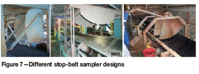
A range of different stop-belt sampler designs are shown in Figure 7. The width of the frame should be not less than three times the top size of the crusher product fed to the plant, and the blades of the frame should follow the curvature of the conveyor belt over the entire width of the belt.
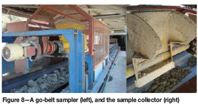
An example of a go-belt sampler can be seen in Figure 8.
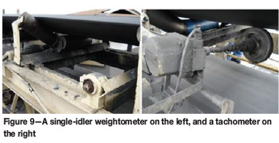
Sampling ROM ore with a cross-stream or go-belt sampler at regular mass intervals overcomes the costly and impractical stopping of the belt and interrupting the shaft or plant operation. The go-belt sampler, also called a hammer sampler, is a robust instrument which is widely used in the industry despite the many problems associated with it (Pitard, 2005). Samples should be collected only on a mass basis (and not a time interval) to provide for fluctuating mass loads on the conveyor. Collection of a ROM sample increment by the go-belt sampler should be initiated once a predetermined mass of ore has passed over the weightometer. A weightometer is a mass meter or weighing instrument that is installed beneath a conveyor belt for the purpose of continuous mass determination. It measures the amount of ore on the conveyor passing a certain idler or number of idlers included in a weigh frame. In general, the more idlers on a weigh frame the less the effect of belt tension and alignment and the longer the instrument will remain in calibration. Figure 9 shows a single-idler weightometer, i.e. one row comprising three idlers on a weigh frame. The tachometer, which measures the speed of the conveyor, is shown in the picture on the right. Together these instruments provide the data for the mass per unit time calculation, i.e. mass flow measurement. The semivariogram procedure (Gy, 1982) should be used to quantify segregation and determine the optimum go-belt sampling frequency
At some mines the samplers operate on a time rather than a mass basis. The variance of the IWE is a function of the variation in the flow rate of the stream from which the increments are collected. Samples should therefore be collected on a mass basis rather than a time basis, as the amount of ore on the conveyors varies. Furthermore, the IWE is zero when the mass of the increment is constant. Some mines have installed profile detector laser beams that prevent the sampler from initiating the extraction of an increment if a large rock is detected or while the profile of the ore on the conveyor is either below or above certain predetermined limits. Oversize material should be removed from the conveyor to prevent damage to the sample collector and conveyor belt.
Secondary sampling
Sub-sampling of broken ore composites involves sample mass and particle size reduction. However, the splitting at different nominal top sizes, crushing, and comminution of the ore should be done according to a specific protocol. The variance of the FSE, σFE2, identified by Gy (1982), is the absolute minimum sampling error for a given fragment size and sample mass. It can be reduced by decreasing the nominal fragment size or by increasing the mass of the sample. The FSE variance can be calculated prior to the sample being taken and is a means of determining the correct sample mass. Minnitt et al. (2007) describe the 32-piece sampling tree experiment and how to determine a sampling protocol that will ensure that the FSE does not exceed a predetermined precision at any stage of the sampling procedure.
Rock dump sampling was not investigated as it is usually part of an ad hoc sampling campaign and not included in the metal accounting programme. Several stockpile sampling methods are available, e.g. drilling, auger, excavation grab, and belt sampling. Grab sampling provides information on the sample itself and is unsuitable for any accounting purposes, but it is usually an easy and inexpensive alternative to other methods.
Plant feed sampling
The flow meter and densitometer are the principal instruments for mass measurement in the metallurgical plant and in the metal accounting system. Six of the mines investigated do not use weightometers, but rely on flow meters and densitometers to measure the amount of ore delivered to the plants as these instruments have a smaller margin of error than a weightometer. One mine uses a single-idler weightometer, 24% of the operations have two-idler-, 33% have four-idler-, and 10% have six-idler weightometers for recording these measurements. Only six-idler weightometers are considered sufficiently accurate for metal accounting purposes. Weightometers should be calibrated weekly using a zero test, i.e. an unloaded running conveyor, and a static weight test, i.e. running conveyor loaded with measured mass pieces or a calibrated chain as shown in Figure 10 a and b.
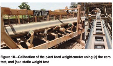
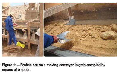
Figure 11 shows broken ore being grab-sampled off a moving conveyor belt by means of a spade. Such grab 'samples' can only be termed specimens, as they do not conform to the principles of correct sampling in that particles of broken ore at the bottom of the load on the belt have no chance of being selected in the sample. Larger particles similar to the rock on the right hand side of the picture will also never be collected from the moving conveyor.
Stop- and go-belt samplers have inherent structural problems that contribute to the TSE even when correctly designed.
Mechanical deficiencies of go-belt samplers are such that they contribute to the IDE, IEE, and IWE, meaning that a correct increment is hardly ever collected from a conveyor for a variety of reasons:
►In correct operation of the go-belt sampler, the collector should move through the stream at a constant high speed, collecting a complete cross-section of the stream, and stop away from the stream. The collector should be self-cleaning such that a complete increment is discharged and no material should remain in the collector
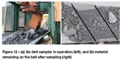
►Motors should be adequately powered in order to drive the collector at a constant speed through the material on the conveyor. An example of an incorrectly designed go-belt sampler is shown in Figure 12a: the collector is stuck in the load on the belt.
►Motors should be adequately powered in order to drive the collector at a constant speed through the material on the conveyor. In Figure 12a the collector is stuck in the load on the belt
►If the capacity of the collector is insufficient to hold the increment, most of the material will be pushed off the belt rather than being collected in a scooping action
►If material escapes from the sides of the collector and an incomplete increment is collected, a large portion of the increment remains on the belt after sampling as shown between the lines indicating the trajectory of the collector in Figure 12b. This particular IEE can be partially mitigated by installing a rubber lip at the rear end of the collector and by supporting the belt where the cutter crosses it.
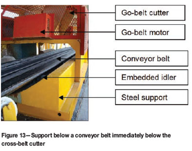
The sampler should be enclosed as shown in Figure 13 to prevent injury from flying rock chips. Inspection doors should be available for access to all parts of the sampler. The collector opening of a cross-stream sampler should be at least three times the nominal top size of the particles and not less than 10 mm for fine dry solids and a minimum of 50 mm for wet solids. A rubber lip must be installed on the cutter edge of a hammer sampler to ensure a clean sweep of the belt. Support, in the form of a plate and idlers or just idlers, below the conveyor (Figure 13) can assist the cutter in collecting the fines from the belt.
The collector opening should be parallel or radial for linear or Vezin-type collectors respectively and intersect the stream at a right angle to the mean trajectory of the stream. It is usual that fines remain on the belt whether the sample is collected by the hammer sampler or the operator performing stop-belt sampling. Stop-belt sampling is an interruption of the production process and operators try to collect the sample as quickly as possible to minimize the interruption.
Many operations have not planned for the increasing demand on sample assays, and so equipment for preparing broken ore samples, crushers, mills, rotary splitters, and ovens are generally inadequate and timeworn. However, some mines have requested up-to-date sampling protocols and new equipment. François-Bongarçon (1995) proposed an experimental procedure to determine the sampling parameters for different ores at a specific average grade. These parameters can then be used to construct the nomogram which provides the protocol so that the FSE does not exceed a predetermined precision at any stage of the sampling procedure. Some mine managers are aware that the fundamental error variance and a nomogram for their particular ore type can be calculated, and that the nomogram forms the basis for a well-founded sampling protocol once the grade interval for the values reported has been determined.
Metallurgical plant sampling
This section includes head, residue, and bullion sampling. Once broken ore has been milled it is slurried by the addition of reagents and water and the slurry is sampled after thickening en route to the leaching area. A variety of methods are employed to sample the slurry, including grab sampling, cross-stream launder samplers, in-line cross- stream samplers, injector samplers (also called poppet samplers), and in-line pipe diversions and probes. Mass flow measurement using flow meters and densitometers in the headlines takes place at 67% of the plants, while the remainder of plants have poorly maintained slurry mass flow equipment.
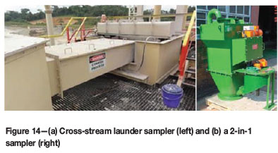
Primary sampling to obtain head and residue grades is done using cross-stream samplers, which deliver unbiased samples if the equipment has been correctly designed, installed, operated, and maintained (Wortley, 2009). Cross-stream launder samplers and 2-in-1 type samplers have a collector that moves across the slurry stream at regular intervals and samples the complete stream part of the time. The 2-in-1 sampler consists of the primary cross-stream sampler that is mounted in a vertical open-ended downward flow line and a secondary Vezin-type sampler that is attached to the unit. Examples of a cross-stream launder sampler and 2-in-1 sampler as manufactured by Multotec are shown in Figure 14.
Grab sampling tools
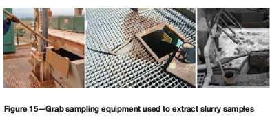
Three metallurgical plants perform grab sampling and two use poppet samplers. All the other operations use 2-in-1 or launder samplers to collect cross-stream samples. The three grab sampling tools shown in Figure 15 are used to collect hourly specimens from the flow to the first leach tank at the three different gold plants. The increments are composited into a daily head sample.
Cross-stream cutters
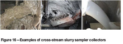
Collectors of different cross-stream samplers are shown in Figure 16 moving through the falling pulp stream. The cutter on the left is engulfed by the slurry which flows over, under, and out of the collector. The collector in the middle cannot accept all the particles in the stream as the opening is covered by a screen. The purpose of the screen is to prevent rock chips from entering the collector and subsequently choking the outflow line. These samplers are structurally incorrect as not all the particles in the pulp have the same chance of being selected in the sample. The cutter on the right is adequately sized to accept the entire cross cut of the non-turbulent stream.
Vezin and 2-in-1 samplers
Secondary sub-sampling of slurries is generally performed by Vezin-type rotary splitters. Vezin-type sub-samplers are in operation at 71% of the plants, and samplers that merely imitate Vezin- and linear-type samplers, such as the flexible discharge tube periodically moved by a piston and the rotating tube divider, are usually biased and should not be used. As with rotating sample dividers, these samplers are biased because momentum is imparted to the flow of material other than that due to acceleration of gravity, resulting in complex and uncontrollable fluid mechanics conducive to sample incorrectness.
For correct use of the cross-stream launder sampler, the flow rate of the stream should be between 2 m/s and 10 m/s. The stream in the launder should be non-turbulent at the point of sampling to minimize splashing when the collector moves through the stream. The collector size and drain system should be adequate to accept the full flow during sampling. The blades of the collector should be of stainless steel and fixed parallel 10 mm or more apart. The collector should start outside the stream and reach constant speed before entering stream. The speed of the collector should not exceed 0.6 m/s. The motor should be sized to maintain a constant speed inside the stream. The collector should move through the entire stream and stop outside the stream away from any splashing. The collector should be adequately sized to accept the entire crosscut of the stream. The collector blades should move at a right angle to the stream.
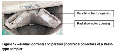
A Vezin sampler is a uniformly rotating cutter that cuts a vertical stream of material in free fall. Figure 17 shows the collectors of a Vezin-type sampler, one of which has radial cutter blades, the other being parallel. Since radial collector blades conform to the requirements for a correct sampler, the parallel blades on the right-hand cutter will collect biased samples.
The inline 2-in-1 sampler and Vezin-type sampler must be installed in a vertical gravity flow line. The cutter edges of the collector should be radial with respect to the centre of rotation and a minimum of 1 cm apart. The distance between the stream discharge and the cutter edges should be more than 2 cm. The angular speed of the tip of the collector should be less than 45 cm/s for units with a diameter larger than 60 cm and less than 30 cm/s for smaller diameter samplers. The distance between the farthest point from the axis where the stream is cut and the outer end of the collector should be a minimum of 5 cm. The same requirement applies to the distance between the inner end of the collector and the point where the stream is intercepted. The blades should be symmetrical and blunt with a flat area of approximately 0.75 mm. The outer slope of the blades should be at an angle of approximately 70°. The capacity of the collector and the discharge should be sufficient to cater for the entire cross-cut of the stream. The operator should inspect the samplers every 2 hours. A checklist similar to Appendix 8 in Spangenberg (2007) should be completed at the start and end of each shift. An accounting sample is so important that every endeavour should be made to repair a sampler breakdown within the same shift in which it occurred. The sampling frequency should be not less than once every five minutes (Bartlett and Hawkins, 1987) to cater for variance in the pulp stream e.g. fine carbon breakthrough.
Cleaning of Vezin samplers
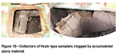
The collectors of the Vezin-type sub-samplers samplers shown in Figure 18 were correctly designed, but a missing cleaning cycle to keep the radial collectors free of accumulated material means the sampler will collect an incomplete increment and hence a biased sample.
An adequately sized inspection door should allow for unobstructed viewing of the collectors. A set of spray nozzles should be installed on each side of the stream in such a way that the spray water covers the complete length of the blades. Potable water should be used in the cleaning cycle. The cleaning cycle should commence after each cut and only after sufficient time has been allowed for the sample to pass the secondary sampler. The secondary cleaning cycle should be initiated manually once per shift when the sample container is removed and the hatch of the holding bay is closed. A pressure switch in the holding bay should interlock the cycle to prevent accidental discharge of water into the sample container.
Dry slurry sampling
Cascade rotary splitters and riffle splitters may be used to split the dried slurry pulp. However, using a rotary splitter is time-consuming considering the relatively small amount of material that has to be split out. Sometimes moist filter cake is divided by combining opposite slices of the cake that is collected as a sub-sample before drying. About 30 per cent of the plants reduce the mass of the primary head sample by dividing the filter cake, and selecting a portion from a coning-and-quartering sub-sample. Coning-and-quartering is usually performed incorrectly as the dried pulp is only rolled from the one side of the paper to the other. This action aggravates the grouping and segregation of dense gold particles rather than promoting proper mixing.
The influence of sampling errors on samples collected in the plant is a concern as head grade sampling is the core of the metal accounting system. Some companies have a code for the reconciliation of produced grade and tonnage. These codes demand due diligence in terms of mass flow measurement and sampling for metal accounting purposes. Three metallurgical plants perform grab sampling and two use poppet samplers to collect head grade samples. Three operations sample the pulp leaving the plant by means of grab sampling and four plants use poppet samplers. These plants collect biased samples and the potential effect of all the sampling errors was rated at maximum. A few years ago, AngloGold Ashanti and Multotec embarked on a programme to develop a cross-stream sampler that conforms to the theoretical requirements of a correct sampler (Spangenberg, 2007). The design was endorsed by Frangois-Bongargon and has since been installed at 12 of the gold plants visited. Incorrect sampling is inexcusable considering the impact of decisions made based on incorrect sample values and the fact that the technology and specialist advice are available.
Bullion sampling
The bullion is dip-sampled by inserting the tip of a vacuum-sealed glass tube into the melted bullion. The glass melts and the vacuum sucks fluid metal into the tube, which is then immersed in water to cool and solidify the sample. Drilling of bullion bars is a laborious but more correct method. The bar should be drilled right through in a randomly chosen position and not where a 'soft spot' is found that can be easily drilled. The bullion bar in Figure 19 was drilled 18 times. The drill penetrated only a few millimetres as an amalgam of several metals formed an extremely hard product that could not be easily drilled with a hand-held unit. A mounted heavy-duty drill is suitable for the task. Two metallurgical plants sample bullion by means of dip sampling and 90% of the plants use drilling. The bullion in the smelter and in the final bar contains impurities in the form of metals and would therefore be segregated.
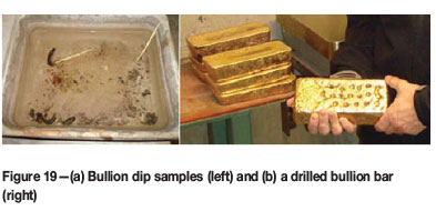
The bullion produced by the metallurgical plants is delivered to refineries for purifying and marketing of the final product. All the refineries sample the molten bullion by means of dip sampling and the mines are compensated according to these sample values. The dip sampling method is an accepted industry standard, and even though it cannot extract a correct sample it is considered better than partial drilling of the bullion bar. Drill sampling is correct when the bar is drilled right through in random selected positions.
Sampling in the laboratory
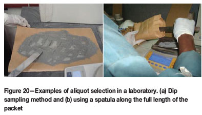
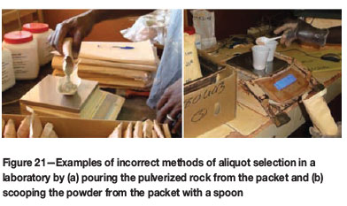
Aliquot selection is amongst the most important responsibilities of the analytical laboratory. The dip sampling method, also known the Japanese slab cake method, for collecting an unbiased sample of pulverized rock powder in the analytical laboratory has been described by Pitard (1998) and François-Bongarçon (2002). The method consists of spreading the powered material on a flat surface and taking as many shallow scoops from as many localities as possible until the mass of the aliquot is made up. The method shown in Figure 20 is considered by most laboratories as best practice since it ensures that the entire sample has an equal opportunity of being selected as the portion for assay. Some laboratories find the method too time-consuming and use a simpler method described in the Anglogold Ashanti Laboratory Guideline (Maree, 2007, p. 2). This specifies that: 'Multiple portions of the sample are removed with a thinbladed spatula while holding the packet at an angle, running the spatula down the entire side of the packet and lifting upwards. This procedure is repeated until the desired aliquot mass is obtained.' The sample in the bag should not be stirred in an attempt to mix it as this will promote segregation of the high-density gold grains.
Both the dip and spatula sampling methods are time-consuming and it is likely that the operator will follow a simple route by pouring material from the packet (Figure 21a) or by using a spoon (Figure 21b).
Sub-sampling in the laboratory is a point for discussion in many audit reports. Laboratory personnel believe that the crushed and pulverized sample is sufficiently well-mixed and that an aliquot from the mill bowl or sample bag can be taken using a spoon or spatula. A cascade rotary splitter is ideal when there are few samples to be assayed, but far too time-consuming to use in a production environment. The IPEs have high potential influences on laboratory sampling practice. The tilted packet method may be used by laboratories that analyse large numbers of samples, e.g. grade control samples.
Views of management relating to sampling
Codes of practice (COPs), standard operating procedures (SOPs), and planned task observations (PTOs) are important technical documents that should exist at a corporate level to provide managers with an uncluttered way of thinking about sampling practices. The COP defines the requirements for sampling specific materials such as broken ore sampling, slurry sampling for metal accounting, and grade control sampling. The COP should specify design, installation, operation, and maintenance requirements according to the TOS. Where management pays attention to the COP the guidelines can affect and influence sampling practice. COPs exists in 76% of the mines visited. The SOP is usually a complementary document to the COP and should be made available to each sampler. It serves as an instruction manual for the sampling operator and technician. Such documents were found in all the mines that were guided by a COP. PTOs are carried out by comparing the activities of the sampling operator or technician against a checklist which is based on the SOP. Any deviations from the SOP should be pointed out by the observer. Corrective action may take the form of immediate on-the-job training or formal training. The PTO has a high potential effect on sampling practice and 71% of the mines perform PTOs.
The costs of sampling installations and new equipment are usually hard for management to accept because the adverse effects of poor sampling practice never appear on the balance sheet. The mining industry is replete with stories about the adverse effects of trying to save money on sampling equipment and installations. Management who are aware of the importance of sampling variability and the secret costs incurred due to poor sampling practice will ensure that sampling equipment is installed, operated, and maintained at an appropriate level. Financial constraints may have a moderate to severe influence on sampling practice, and it was found that 52% of the mines do not have capital to spend on new sampling equipment. Mines in this position resort to grab sampling and inexpensive alternatives such as poppet samplers. In general managers are ill-informed with regards to good sampling practice and are satisfied with advice about sampling equipment purchases that resulted in savings irrespective of the demands of TOS. Ten mines of the 21 mines visited had budgets to maintain existing samplers and related practices, such as the purchase of standard reference materials. Only 10% of the mines were in a position to design and install new samplers to replace outdated equipment.
Formal internal audits to ensure adherence to the COP are carried out regularly at only 43% of the mines. Deviations from the COP should be addressed at managerial level as the economic impact of poor sampling can be enormous. External audits should, as a minimum requirement, be carried out annually by sampling specialists from outside the mining operation. All the mines arrange irregular external audits.
While all the mines have on-the-job sample operator training, it is imperative for the operations manager to attend a formal sampling course. An appreciation of the TOS by management will encourage a positive approach to elements of management that influences good sampling practices, e.g. the availability of capital for sampling equipment and training of operators.
Usually a person who has attended one of the sampling courses provided by international consultants and who has developed a sound knowledge of the TOS can be groomed to champion the cause of good sampling practice within the mine. Such champions can teach operators in the workplace how to operate and maintain a sampler, but only 43% of the mines have such a person. Mines or companies that have no individual competent in the principles of sampling should seek advice from consultants, as is the case with 29% of the mines visited. Equipment suppliers are often called on to provide advice for companies installing new equipment, and require a good level of understanding of TOS when advising the client about equipment purchases and installation. Only 24% of the mines seek advice from salesmen.
In conclusion, management should be the driving force behind good sampling practice. The lack of formal training in sampling among managers translates into insufficient budget for the design, installation, maintenance, and operation of correct samplers. However, on most mines an awareness of the importance of good sampling practice has led to the best available sampling equipment being purchased and installed. Unfortunately, this does not mean that the samplers are always operated correctly. Designated persons on the mine and in the company should ensure that the basic documentation that drives good sampling practice should be in order, i.e. COP, SOP, and PTO. The necessary training and inspiration for operators must come from the champions who will also perform regular audits and PTOs.
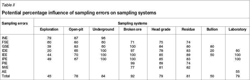
The data in Table II presents the general picture of the potential influence that the sampling errors might have on the sampling systems in specific areas (Spangenberg, 2012).
The total potential influence of all the sampling errors on all the sampling systems was an average 73.7%. The potential influence of the relevant sampling errors is high in all areas of sampling in this study except for exploration and bullion sampling, where it was found to be moderate. Although the potential influence of management and related principles was rated as moderate, some elements have a high potential influence on sampling practice e.g. COP, SOP, and PTO.
Conclusions
The financial consequences of incorrect, poor, and insufficient or no sampling can be devastating. A bad blasthole sampling protocol that was erroneously implemented cost a mine US$134 million over a 10-year period (Carrasco et al., 2004). They also reported that incorrect sampling of flotation tailings amounted to US$2 billion over a 20-year period for a specific mine. The recent increases in the gold price would inflate these losses even more in current monetary values. Only through the correct application of the principles of TOS from exploration through mining and metallurgical recovery to sampling of the final product can we be certain that estimates of grade are acceptable. A small financial saving in terms of the purchase of sampling equipment now may end up costing the company a fortune later. It could mean the difference between pursuing the exploration results and building a mine or deciding that the orebody is below the cut-off grade and the project is not feasible. In both cases millions of dollars are at stake, as explained in Minnitt (2007), in terms of capital expenditure, employment opportunities, and foreign income.
It is recommended that the summary of rules, principles, and leading practice found in the theory and current operating procedures as summarized in Table III be adopted as a basis for an international standard for sampling practice in the gold mining industry. The table provides a summary of the rules, principles, practice, and available technology.
References
Almonte Diamond Pty Ltd. 2011. http://www.almontecoresaw.com.au/[accessed 30 Nov. 2011]. [ Links ]
Bamber, C. 2012. Material Sampling Solutions, Germiston. Personal communication. [ Links ]
Bartlett, H.E. and Hawkins, D.M. 1987. Process evaluation. The Extractive Metallurgy of Gold in South Africa. vol. 2. Stanley, G.G. (ed.). Monograph Series M7. Southern African Institute of Mining and Metallurgy, Johannesburg. pp. 745-792. [ Links ]
Boart Longyear. 2011. Genuine Q™ coring system product overview. Brochure. Salt Lake City, UT. 4 pp. [ Links ]
Carrasco, P., Carrasco, P., and Jara, E. 2004. The economic impact of correct sampling and analysis practices in the copper industry. Chemometrics and Intelligent Laboratory Systems, vol. 74. pp. 209-213. [ Links ]
CAWOOD, F.C. 2003. Underground face sampling on narrow gold reefs: sampling practice and its impact on the Mine Call Factor on Witwatersrand gold mines: lessons learnt. Journal of the Institute of Mine Surveyors of South Africa, vol. XXXI, no. 7. pp. 202-224. [ Links ]
Flitton, T. 2009. Standard underground chip sampling. Anglogold Ashanti Ltd, Johannesburg, South Africa. 18 pp. [ Links ]
FRANÇOIS-BONGARÇON, D.M. 1995. Sampling in the mining industry theory and practice.Volume 1: Course notes and transparencies. School of Mining Engineering, University of the Witwatersrand, Johannesburg. [ Links ]
FRANÇOIS-BONGARÇON, D.M. 2002. Sampling in the mining industry, theory and practice.Course notes. School of Mining Engineering, University of the Witwatersrand, Johannesburg. [ Links ]
FRANÇOIS-BONGARÇON, D.M. 2008. A brief history of Pierre Gy's sampling theory and current trends in its acceptance in the mining world. Proceedings of Sampling 2008, Perth, Australia, 27-29 May 2008. Australasian Institute of Mining and Metallurgy, Melbourne. pp. 13-14. [ Links ]
FRANÇOIS-BONGARÇON, D.M. and Gy, P.M. 2002. The most common error in applying 'Gy's Formula' in the theory of mineral sampling and the history of the liberation factor. Journal of the Southern African Institute of Mining and Metallurgy, vol. 102. pp. 475-479. [ Links ]
Gy, P.M. 1979. Sampling of particulate materials, theory and practice. Elsevier, Amsterdam. [ Links ]
Gy, P.M. 1982. Sampling of particulate materials, theory and practice. 2nd edn. Elsevier, Amsterdam. [ Links ]
HOLMES, R.J. 2009. Sampling mineral commodities - the good, the bad and the ugly. Proceedings of the Fourth World Conference on Sampling and Blending, Cape Town, South Africa, 21--23 October 2009. Southern African Institute of Mining and Metallurgy, Johannesburg. pp. 203-210. [ Links ]
Kelly, S. 2006. Standard underground chip sampling. AngloGold Ashanti Ltd, Johannesburg, South Africa. 15 pp. [ Links ]
Lyman, G.J. 2011. In situ and particulate material heterogeneity. Proceedings of 5th World Conference on Sampling and Blending (WCSB5), Santiago, Chile, 25-28 October 2011. Alfaro, M., Magri, E., and Pitard, F. (eds.), Gecamin Ltda, Santiago, Chile; Melbourne. pp. 3-21. [ Links ]
Maree, D.C.S. 2007. AngloGold Ashanti Africa chemical laboratory guideline. AngloGold Ashanti Ltd, Johannesburg, South Africa. 115 pp. [ Links ]
Minnitt, R.C.A. 2007. Sampling: the impact on costs and decision making. Journal of the Southern African Institute of Mining and Metallurgy, vol. 107. pp. 451-462. [ Links ]
Minnitt, R.C.A. 2010.The state of sampling practice in the South African Minerals Industry. Proceedings of Sampling 2010, Perth, Australia, 11-12 May 2010. Australasian Institute of Mining and Metallurgy, Melbourne. pp. 31-50. [ Links ]
MINNITT, R.C.A., RICE, P.M., and SPANGENBERG, I.C. 2007. Part 2: Experimental calibration of sampling parameters K and alpha for Gy's formula by the sampling tree method. Journal of the Southern African Institute of Mining and Metallurgy, vol. 107. pp. 513-518. [ Links ]
MULTOTEC. 2012. http://www.multotec.com/content/multotec-market-share-all-time-high [Accessed 16 Jun. 2012]. [ Links ]
Pitard, F.F. 2005. Sampling correctness - a comprehensive guideline. Proceedings of the Second World Conference on Sampling and Blending, Queensland, Australia, 9-12 May 2005. Australasian Institute of Mining and Metallurgy. Melbourne. pp. 55-66. [ Links ]
PITARD, F.F. 2006 .Sampling theory and methods.Course notes. School of Mining Engineering, University of the Witwatersrand. Johannesburg. [ Links ]
Pitard, F.F. 2009. Blasthole sampling for grade control - the many problems and solutions. Proceedings of Sampling 2008, Perth, Australia, 27-29 May 2008. Australasian Institute of Mining and Metallurgy. Melbourne. pp. 15-21. [ Links ]
POLLARD, D, PITARD, F.F., and MINNITT, R.C.A. 2009. Misconceptions, rumour, and hearsay about sampling.Proceedings of the Fourth World Conference on Sampling and Blending, Cape Town, South Africa, 21--23 October 2009. Southern African Institute of Mining and Metallurgy. Johannesburg. pp. 177-182. [ Links ]
PRINSLOO, J. 2012. QAQC and grade control sampling. AngloGold Ashanti Ltd, Johannesburg. South Africa. 23 pp. [ Links ]
ROBINSON, G.K. 2008. Checking precision and bias before and after construction of sampling systems. Proceedings of Sampling 2008, Perth, Australia, 27-29 May 2008. Australasian Institute of Mining and Metallurgy. Melbourne. pp. 115-119. [ Links ]
SAMREC. 2009. South African Code for the Reporting of Exploration Results, Mineral Resources and Mineral Reserves (The SAMREC Code). Prepared by the South African Mineral Resource Committee (SAMREC) Working Group under the Joint Auspices of the South African Institute of Mining and Metallurgy and the Geological Society of South Africa. Johannesburg. South Africa. [ Links ]
Sandvik.2008. Operation, maintenance and parts manual of the Sandvik vrX70i series sampling systems. Sandvik Mining and Construction, Welshpool, Perth, WA [ Links ]
Sichel, H.S. 1947. An experimental and theoretical investigation of bias error in mine sampling with special reference to narrow gold reefs. Transactions of the Institute of Mining and Metallurgy, Bulletin no. 485. [ Links ]
SPANGENBERG, I.C. 2007. A standard for broken ore-, plant head- and residue sampling in a typical gold mine. Proceedings of the Third World Conference on Sampling and Blending, Porto Alegre, Brazil, 23-25 October 2007. Fundação Luiz Englert. pp. 282-328.
Spangenberg, I.C. 2008. Standard for quality assurance and quality control. AngloGold Ashanti Ltd.Johannesburg. [ Links ]
Spangenberg, I.C.. 2012. The status of sampling practice in the gold mining Industry in Africa: working towards an international standard for gold mining sampling practices. MSc dissertation, School of Mining Engineering, University of the Witwatersrand, Johannesburg. [ Links ]
Storrar, C.D. 1987. South African mine valuation. Chamber of Mines of South Africa, Johannesburg. [ Links ]
Wortley, C.M.G. 2009. Mass measurement for metal accounting - principles, practice, and pitfalls. Proceedings of the Fourth World Conference on Sampling and Blending, Cape Town, South Africa, 21-23 October 2009. Southern African Institute of Mining and Metallurgy, Johannesburg. pp. 121-128. [ Links ]
1 Spangenberg, I.C. 2012. The status of sampling practice in the gold mining industry in Africa: working towards an international standard for gold mining sampling practices. MSc dissertation, School of Mining Engineering, University of the Witwatersrand, Johannesburg.

