


Serviços Personalizados
Artigo
 Inglês (pdf)
 Artigo em XML
 Referências do artigo
Indicadores

Links relacionados
-
 Citado por Google
 -
 Similares em Google
Compartilhar

 Permalink
Journal of the Southern African Institute of Mining and Metallurgy
versão On-line ISSN 2411-9717
versão impressa ISSN 2225-6253
J. S. Afr. Inst. Min. Metall. vol.113 no.4 Johannesburg Abr. 2013
PAPERS
Utilization of ISO 6892:2009 testing standard for determining tensile properties of TM380 mild steel
L. ShokeI, II; T.J. SonoI; P.A. OlubambiIII
IDefence Peace Safety and Security, CSIR, Pretoria
IITshwane University of Technology, Tshwane (Pretoria)
IIIDepartment of Chemical Engineering and Metallurgical Engineering, Tshwane University of Technology, Tshwane (Pretoria)
SYNOPSIS
The aim of this study was to develop an in-house tensile testing procedure that would yield accurate and reproducible parameters as input material properties into computational models for numerical simulations of the mechanical behaviour of TM380 mild steel. To achieve this objective, we reviewed the ISO 6892:2009 tensile testing standard along with reported good practice guidelines. Tensile tests were conducted on a dog-bone shaped TM380 mild steel specimen with strain gauges attached on either side, to monitor alignment and measure strain, using three different types of tensile testing machines. Parameters quantified included yield stress, ultimate tensile strength, and modulus of elasticity. The values of these parameters were found to be in agreement with the values supplied by the manufacturer's specification and showed minimal variations between laboratories. Thus it can be concluded that the tensile test procedure used resulted in accurate and reproducible results. The strain values calculated as per standard were in disagreement with those determined from extensometer and strain gauges and resulted in lower elastic modulus values. This confirms that the current testing procedures require the use of long-range strain gauges or extensometer to determine the strain. A chemical analysis was conducted to verify the specification by the manufacturer. The specimen was found to be fairly homogeneous with minor sulphide inclusions. The micrographs reveal a pearlite and ferrite structure typical of mild steel, and the fractographs show a dimpled surface typical of ductile fracture, which is an attribute of mild steel.
Keywords: TM380 mild steel, tensile properties, ISO 6892:2009, reproducibility.
Introduction
Ascertaining the reliability of materials in service is an important engineering practice for safe and efficient industrial operations. Depending on the manufacturer's specifications, engineers must ascertain a material's suitability for a given application through acceptable tests procedures whenever materials are procured and before use. It is therefore very important to understand the relevant material properties requirement for a specific application and how the properties are obtained. In order to obtain reproducible and accurate results the use of appropriate testing methods that are carried out using approved standard conditions is required.
Tensile testing is a simple and inexpensive procedure that is routinely used in industry to quantify the mechanical properties of materials (ASTM 1997). It is the most common materials testing method that reveals several important mechanical properties, such as yield strength, modulus of elasticity, ductility, ultimate tensile strength, and toughness. Tensile testing is often used for quality control and to ensure consistency in manufacturing products according to the suppliers' specifications, and to find the safety range of materials to aid design processes (Meyers 1994). Uniaxial tensile properties of materials are used directly as one measure of material performance and as part of the material property input required for analysis of complex structures (Kohlman et al., 2012).
Various test methods are available to assess the tensile behaviour of materials. Commonly used tensile testing techniques include the split Hopkinson pressure bar (SHP B) and the drop weight impact tester. The tensile split Hopkinson pressure bar (TSHPB) measures properties such as flow stress, yield stress, strain hardening, and shear stress (Nicholas 1981). It can test at high strain rates of from 102/s to 104/s and correlate the tensile test and torsion test data (Johnson and Cook, 1983). However, it is not useful at low strain rates (Li and Liu, 2012) and the data cannot be accurately evaluated after necking begins (Johnson and Cook, 1983). The drop weight impact tester can be used to characterize material at strain rates of up to 100/s, using both tensile and compression testing (Li and Liu, 2012). The quasi-static tensile testing procedures are relatively simple and reproducible methods, which are readily available and more cost-effective than the SHPB and drop weight impact tester.
During tensile testing, a tensile load is applied to a test specimen and the displacement and applied force and elongation of the specimen are measured. Although tensile testing is relatively simple, there are many issues that can affect the reliability of the measured value (Kohlman et al., 2012). Important tensile test parameters include the loading method, speed of testing, gripping methods, test piece dimensions, and the test machine factors (Loveday et al., 2004). Depending the on testing parameters, different materials yield at different strength levels, and the ability to predict the loads that will cause a part to fail depends upon both material properties and the geometry of the specimen.
Although tensile testing is a relatively cheap and simple method, it requires a thorough understanding of the inputs to obtain the desired output. Through this, the uncertainties inherent in the tensile testing procedure can be limited and accurate and reproducible test results produced. Moreover, materials tested in compliance with the testing standards should yield similar information regardless of the laboratory at which they were tested. Calibration, accuracy, and precision are important factors in any standards employed for mechanical testing, and estimation of uncertainty provides a methodology to propagate this importance through to the test results (Tarafder and Gupta, 2004). This study employs ISO 6892:2009, which is a compilation of the ASTM E8 and EN 10002 and an improved version of the tensile standard for determining the tensile properties of TM380 mild steel. The aim is to use the tensile parameters for developing an in-house procedure to characterize the mechanical properties of the steel in its elastic and inelastic regions on a routine basis, in order to study new materials that could be used in the field of explosive blast research (EBR).
Experimental procedure
Review of testing procedure
The tensile testing procedure presented in ISO 6892:2009 was reviewed in conjunction with the modifications recommended by Lord and Morrell (2010). From the review, a revised tensile testing procedure was drafted.
Materials and sample preparation
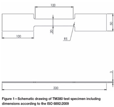
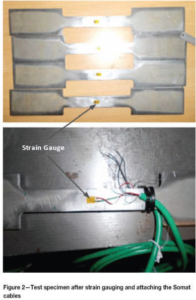
The samples used for this study were sheets of mild steel (TM380) procured from ArcelorMittal Steel. The samples were sectioned to produce the desired 'dog-bone' shaped specimens, according to Annex D of the ISO 6892:2009, using a water jet cutter at the CSIR LS mechanical workshop. The dimensions of the specimen were 330 mm in overall length, 100 mm in grip length, 120 mm in reduced section, and 3 mm in thickness as shown in Figure 1. The surface of the specimen was cleaned using sandpaper, cleaning cloths, and RMS1. The strain gauges were aligned parallel and along the edge of the specimen and attached onto the cleaned surface using a Z70 adhesive and left to dry. Strain gauges (1-LY41-6/350) were glued onto either side of the test specimen on the centre of the gauge length as shown in Figure 2. Somat cable with a length of 2 m was connected to the strain gauge by soldering and the strain gauges were calibrated.
Tensile testing procedure
Three different tensile testing machines - a 100 kN Schenck (Hydropuls PSA), 250kN Schenck (Model: PO20857), and 400 kN Instron (Model: 1344) - were used for the tensile test experiments. The tensile testing machines were calibrated for both load and displacement. Tests using the 250 kN Schenck and the 400 kN Instron were carried out in the same laboratory and conducted in an air-conditioned environment with the temperature set at 200°C, while testing using the 100 kN Schenck was carried out in different laboratory at a temperature of 28°C.
The 250 kN Schenck and the 400 kN Instron machines were equipped with pneumatically powered grips, which had a serrated surface and an indented centre line. The specimen was inserted into the bottom grip, aligned, and gripped at a pressure of 75 bar. The top grip was then lowered to grip the top grip section of the specimen at a pressure of 75 bar. The extensometer was used from start until just after yield and removed beyond the elastic region to avoid potential failure when the sample fractured. The strain gauges peeled off from the sample just after the yield point, the load and displacement were recorded until fracture. The 100 kN Schenck tensile testing machine had serrated wedge grip but required manual tightening and torqueing. The testing machine was set in displacement control loading mode. The sample was loaded at a speed rate ranging from 0.02 mm/s to about 0.6 mm/s.
Microstructural analysis
The as-received steel sample was sectioned using an abrasive water-cutting machine and hot mounted using a Bakelite resin. The mounted specimen was then subjected to grinding and polishing, and finally etched in 2% Nital for 5 seconds. The microstructures of the samples were observed using both optical and scanning electron microscopy (SEM), while the quantitative chemical compositions were determined by energy-dispersive X-ray microanalysis (EDS). Fractured surfaces were also observed using SEM/EDS techniques.
Results and discussion
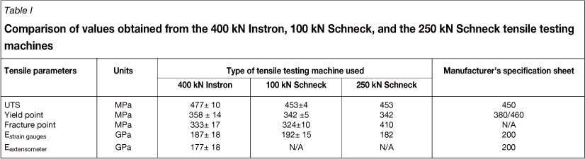
Table I shows the summary of the parameters (shown in Figures 3 to 5) obtained from the tensile tests using the three different types of tensile testing machines. For determination of the Young's modulus, only strain measured from the strain gauges and/or extensometer was used. The yield stress was determined as the maximum engineering stress value at the end of the elastic region. The ultimate tensile strength (UTS) was determined as the maximum engineering stress value in the plastic region.
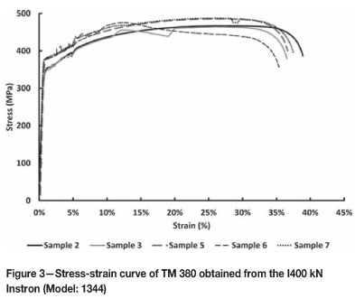
The stress-strain profiles of the samples tested using the Instron tensile testing machine (400 kN Instron, Model: 1344) are presented in Figure 3. From the graph, it is observed that the test samples exhibited very similar elastic behaviours as depicted by the elastic strain values, which were almost in the same range until yielding occurred. The yield strength of the samples varied slightly, ranging between 358±14 MPa (Table I), which is less than 4% variation in the yield strength results obtained by repeated testing with the same machine. There was slightly less variation in the UTS results, which were within the range 477±10 MPa, which is less than 2.1% variation from repeated testing. However, the UTS values measured from the 400 kN Instron machine were about 6% higher than the those (450 MPa) in the manufacturers 'specification. The elastic modulus evaluated with the use of strain gauge and extensometer recorded on average 9.6% and 10.2% variation respectively in repeated testing. However, the elastic modulus from the strain gauge and extensometer were 6.5% and 11.5% lower than the manufacturer's specification. The strain to fracture yielded 36.54±1.25%, which is less than 3.43% variation in the strain values. Thus all tensile properties evaluated with the use of the 400 kN Instron tensile testing machine show very good reproducibility of results.
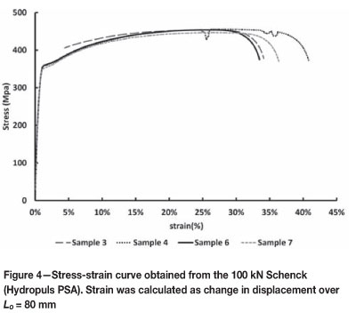
The stress-strain profiles of the mild steel samples tested using the Schneck tensile tester (100 kN Schenck, Hydropuls PSA ) are presented in Figure 4. As in Figure 2, it is observed that the elastic behaviour, particularly the elastic strain, was uniform for all the tested samples. The yield strength of the samples (Table I) is observed to be within the range of 342±5 MPa, which is less than 1.5% variation in the results. The UTS values ranged between 453±4 MPa, indicating less than 0.7% variation in the results. The UTS obtained from the 100 kN Schenck tensile machine is 0.7% above that specified by the manufacturer, which indicates a high degree of accuracy. The elastic modulus derived with the use of the strain gauges is observed to be within the range 192±15 GPa, which represents about 7.8% variation in the values obtained with the use of the 100 kN Schenck tensile test machine and is approximately 4% less than the value of 200 MPa specified by the manufacturer. The strain to fracture, however, ranged between 36.65±3.8, which indicates a variation of over 10.36% in percentage elongation. The wide variation in the strain to fracture is due to the difficulty in accurately measuring the gauge length of the samples.
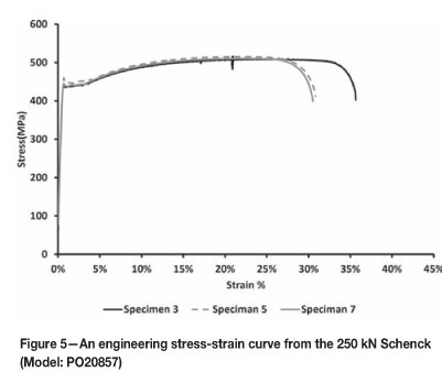
Figure 5 shows the stress-strain profile of the test samples subjected to tensile testing using the 250 kN Schenck (Model: PO20857) at different strain rates specified in the standard. It is observed that the yield strength, elastic modulus, and UTS displayed less than 1% variation for repeated testing. However the capacity to sustain plastic deformation without fracture as measured by the strain to fracture is observed to be within a range of 30-35%.
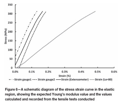
Figure 6 shows a close-up of the engineering stress-strain graph in the elastic region. Here the difference in the calculated strain, and the strain measured from the strain gauges and the extensometer is observed. The strain data (determined from displacement measurements) and Lo as specified in ISO 6892: 2009, Annex D, resulted in lower values for the elastic modulus. The ISO standard specifies the gauge length of the sample according to the width of the test specimen. The width of the test specimen was measured to be 20 mm, thus the original gauge length was 80 mm. The calculated values were in disagreement with those determined from the extensometer and strain gauges. However, using the strain values from the extensometer one can estimate the appropriate Lo for each experiment, which can give the same strain as for each extensometer. The estimated gauge length values were found to range from 191-244 mm for the experiments conducted using the strain gauges and the extensometer methods. These values are larger than the parallel length of 120 mm, which implies that the strain values and strain-related parameters calculated, such as proof stress and inelastic region, will be affected. Therefore measured displacement values cannot be used to determine strain, because either the Lo is not necessarily a known value or the displacement measurement is not a measure of the change in length of the sample within the gauge length. This may lead to a variation from test to test and from one laboratory to another.
From Figure 7, a linear relationship between yield stress and increasing crosshead velocity and equivalent strain rate is observed. Similarly, there is a linear relationship between increasing UTS and the crosshead speed. Increasing the speed, however, did not affect the fracture point of the material. The observed increase in the strain rate while loading the material can result in higher yield stress and UTS values, but depends primarily on the strain rate sensitivity of the material (Subhash et al., 2006). However, fracture strength does not show dependency on the strain rate.
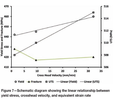
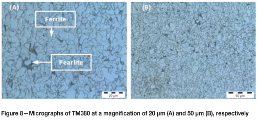
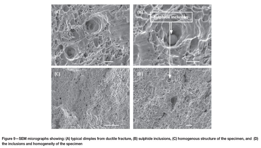
Figure 8 shows typical optical micrographs of the as-received samples, revealing a pearlite and ferrite grain structure typical of mild steel. The pearlite was homogenously distributed in the ferrite matrix. SEM analysis of the fractured surface was conducted to observe the fracture mechanism of the TM380 specimen. Typical SEM micrographs of fractured surfaces shown in Figure 9 revealed ductile fracture typical of mild steel under tensile loading. Minor sulphur inclusions were observed in the samples.
Conclusions and recommendations
► The tensile properties, namely yield strength, UTS, and elastic modulus, derived using the strain gauges and the extensometer methods, yielded accurate results, with good reproducibility, for the samples tested. The results were in good agreement with the manufacturer's specifications
► The strain to fracture values calculated for the tested materials showed less variation with the use of strain gauges and the extensometer in comparison with the displacement method
► The use of strain data determined from displacement measurements and Lo as specified in the ISO 6892: 2009 standard resulted in lower values for the elastic modulus
► The strain rate had negligible effects on the flow stress, yield strength, UTS, and elastic modulus, but the strain to fracture decreased with an increase in the strain rate
► It recommended that the current testing procedures should use strain gauges or extensometers to determine the strain.
Acknowledgements
The authors are grateful for the support from Landward Sciences and the Department of Material Sciences and Manufacturing, CSIR. Thanks to Mr. K. Becker for assistance and permission to use the tensile testing facilities at the Sasol Laboratory at the University of Pretoria. This project was funded by a NRF-NNEP 74407 grant.
References
Astm E8 1997, Standard test methods for tensile testing of metallic materials. Annual book of ASTM standards, vol. 3. West Conshohocken, PA. [ Links ]
Iso. 2009. 6892-1: 2009: Metallic materials -Tensile testing - Part 1: Method of test at room temperature. European Committee for Standardization, Brussels. [ Links ]
Johnson, G.R. and Cook, W.H. 1983. A constitutive model and data for metals subjected to large strains, high strain rates and high temperatures. Proceedings of the 7th International Symposium on Ballistics, The Hague, Netherlands. International Ballistics Committee. pp. 541. [ Links ]
Kohlman, L.W., Bail, J.L,, Roberts, J.D., Salem, J.A., Martin, R.E., and Binienda, W.K. 2012. A notched coupon approach for tensile testing of braided composites. Composites: Part A. doi:10.1016/j.compositesa.2011.12.013 [ Links ]
LI, G. and LIU, D. 2012. Low strain rate testing based on drop weight impact tester. SEM 2009 Annual Conference & Exposition on Experimental & Applied Mechanics. [ Links ]
Lord, J. and Morrell, R. 2010, Elastic modulus measurement-obtaining reliable data from the tensile test. Metrologia, vol. 47, pp. S41. [ Links ]
Loveday, M., Gray, T., and Aegerter, J. 2004. Tensile testing of metallic materials: a review. Final report of the TENSTAND project of work package, vol. 1. National Physical Laboratory, Teddington, Middlesex, UK. [ Links ]
Meyers, M.A. 1994. Dynamic behavior of materials, Wiley-Interscience. [ Links ]
Nicholas, T. 1981, Tensile testing of materials at high rates of strain. Experimental Mechanics, vol. 21, no. 5. pp. 177-185. [ Links ]
Subhash, G., Liu, Q., and Gao, X.L. 2006. Quasistatic and high strain rate uniaxial compressive response of polymeric structural foams. International Journal of Impact Engineering, vol. 32, no. 7. pp. 1113-1126. [ Links ]
Tarafder, S. and Gupta, K.K. 2004. Estimation of uncertainty in mechanical testing. Study Material of Refresher Course on ISO/IEC 17025 Standards, NABL and CGCRI, Kolkata, 27-28 Aug. 2004. [ Links ]
Paper received Dec. 2012
Revised paper received Jan. 2013
© The Southern African Institute of Mining and Metallurgy, 2013. ISSN2225-6253
Paper written on project work carried out in partial fulfilment of BTech. Bachelor of Technology in Metallurgical Engineering

