


Services on Demand
Article
 English (pdf)
 Article in xml format
 Article references
Indicators

Related links
-
 Cited by Google
 -
 Similars in Google
Share

 Permalink
Journal of the Southern African Institute of Mining and Metallurgy
On-line version ISSN 2411-9717
Print version ISSN 2225-6253
J. S. Afr. Inst. Min. Metall. vol.113 n.2 Johannesburg Feb. 2013
Friction Hydro Pillar Process as an alternative repair technology for creep evaluation sites on thick-walled 10CrMo910 creep-resistant steel structures
D.L.H. Bulbring; D.G. Hattingh; A. Botes; D.H. Odendaal
Nelson Mandela Metropolitan University
SYNOPSIS
The removal of a cylindrical core from thick-wall sections for creep analysis by the relatively new Weldcore® process represents a very exciting methodology for obtaining more representative creep damage data from large engineering structures. The cylindrical core that is removed, representing about 60% of the wall thickness, leaves a substantial removal site that needs to be repaired. This paper presents data pertaining to taper Friction Hydro Pillar Processing as an alternative repair technique for filling the core removal site. Process parameters were evaluated with special attention being paid to the effect of downward force on process response variables, weld defects, and mechanical properties of 10CrMo910 steel. Process temperature and torque response as well as total process energy input were also considered. This paper also assesses the static and dynamic performance of this repair technique. The influence of a varying downward force and the occurrence and position of discontinuities were quantified. Downward force was shown to have the most notable effect on weld joint dynamic performance and was found to be related to the process temperatures achieved in close proximity to the weld interface.
Keywords: friction hydro pillar processing, coring, creep damage, welding, downward force.
Introduction
The life expectancy of high temperature and pressure components is predominantly governed by the steady-state creep rate of the parent material. The life monitoring of these components is of paramount importance, as failures can have severe and possibly catastrophic consequences. Remnant life prediction requires reliable knowledge of the in-service creep behaviour on a regular basis to determine the condition of critical components1.
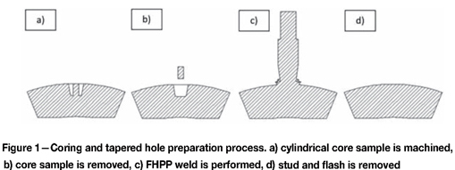
The most common method currently used for microstructure evaluation is surface replication. This technique has limited application in providing creep data that is representative of the through-thickness damage of the component material. Friction Hydro Pillar Processing (FHPP) is a relatively new process that has been earmarked for use together with the extraction of more representative creep samples from thick-walled steam pipes. The non-arc welding technique could facilitate more reliable life extension philosophies1. For example, the residual life of a steam pipe can now be determined more accurately by doing void counting on a more representative sample. Currently, methods of determining creep damage are limited to samples taken close to the outer surface, or are time-consuming and cumbersome.The easiest technique consists of making a replica of the outer surface of the pipe and using statistical methods to estimate through thickness damage2. Other more comprehensive techniques include scooping (gouging) a sample and welding up the resultant cavity, or removing and replacing a section of pipe, both of which require skilled welders and careful planning. Figure 1 shows the unique Weldcore® coring and plugging process that was developed by researchers at Nelson Mandela Metropolitan University (NMMU) as an alternative sampling and repair method (outlined by Wedderburn et al.3). Specialized tools machine a tapered hole leaving a cylindrical core (a) which is then removed from the outer wall of the pipe (b). The resultant hole is then plugged using FHPP (c), the protruding stud is cut-off and the excess material is dressed back (d). This approach allows for shorter turnaround times where downtime can cost millions in lost power generation. Also, the process is semi-automated, which reduces the probability of human error and increases repeatability. Process data feedback from the welding platform allows for analysis of weld parameters as a process control measure for quality assurance.
FHPP is a variant of friction welding that was developed by The Welding Institute (TWI) in the United Kingdom4,5. This process involves concentrically rotating a cylindrical stud under load inside a blind cylindrical hole of a slightly larger size. Frictional heat is generated by the difference in relative velocity between the stud and the parent material at the bottom of the hole, causing an increase in temperature at the faying surface. This in turn weakens the stud material, causing a layer of stud material to shear away from the body of the stud above this interface. Some of the stud material is deposited onto previously recrystallized material, while the rest is sufficiently heated so that it is carried away from the faying surface and is forced outwards and upwards. The stream of plasticized stud material comes into close contact with the inner hole surface, displacing the parent material so a secondary stream is created, and both streams are forced out of the hole opening. The excess plasticized stud material that accumulates above the hole is termed primary flash, whereas the excess plasticized parent material is termed secondary flash6,7. Under the correct conditions, a strong bond is attained between the stud material and the sides of the hole by means of atomic diffusion4.6-8.
Tapers were later introduced to the consumable stud and the hole, with the hole having a nominally larger taper, to force plasticized material to flow upwards by means of the diverging tapers9. This configuration allows for closer contact between the displaced stud material and the sides of the hole, which has benefits for materials that are difficult to forge at temperatures below the melting point. This variant has on occasion been termed Friction Taper Stud Welding (FTSW) 6,10-12. However, this terminology is currently used for welding tapered consumable studs into through holes with an identical taper. FHPP derives its name from the mechanism by which plasticized stud material is deposited onto previously plasticized and recrystallized material, forming the base for the next layer. This mechanism is shared by tapered geometries, so the term is still valid.
FHPP can be used on a variety of materials such as steels(including stainless steel) and, magnesium alloys13. and research is currently being conducted on blind hole applications in aluminium alloy 6082-T6. Acceptable FHPP welds have been produced underwater by both Ambroziak and Gul14 and Andrews and Mitchell^. Andrews et al. used overlapping welds to form a continuous bond. FHPP is therefore a versatile process with many applications. Each material poses its own challenges, even with variations in alloying elements of steel such as carbon, molybdenum, and chromium. The research presented in this paper will show that downward force has an effect on through thickness properties of 10CrMo910 (also known as 2.2Cr-1Mo).
Experimental procedure
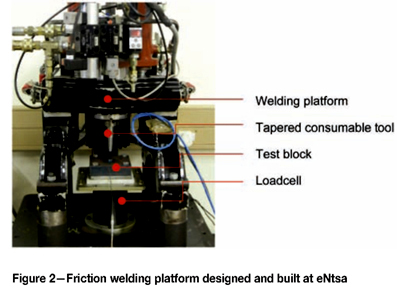
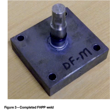
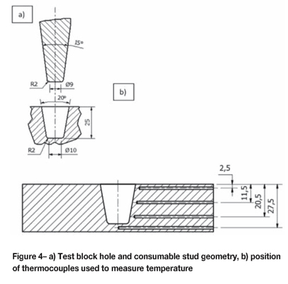
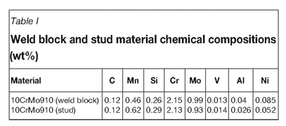
Figure 2 shows the platform used in the experiments and Figure 3 shows a typical completed FHPP weld. A dedicated loadcell verified the loads obtained during welding and measured the torque responses. The geometrical details of the tapered hole after removal of the core and of the stud are shown in Figure 4a. The hole and stud taper angles used for these experiments were 15° and 20° respectively, which have been shown to produce acceptable welds. Table I shows the chemical compositions of the stud and weld block, which are both made from the same alloy.
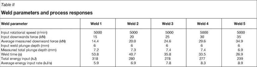
The most important parameters that influence the properties of FHPP joints are downward force, rotational speed, and plunge depth6,7. Based on research conducted on AISI 4140 (Hattingh et al.5), statistical analysis showed that downward force had the greatest effect on weld strength. A rotational speed of approx. 5000 r/min has been shown to be acceptable for a similar size stud 6, while preliminary tests conducted on 10CrMo910 showed that a plunge depth of 6 mm gavea satisfactory weld for this geometry. Table II details the welds that were subjected to macro examination. The welds are denoted as weld 1 to weld 5 for increasing downward forces, in 5 kN increments from 15 kN to 35 kN, along with the actual measured average downward forces. Each weld was preheated to a weld start temperature between 204°C and 250°C as per the welding specification for this grade of steel16. Also specified is a post weld heat treatment (PWHT) of 704°C-760°C. However, no PWHT was performed on the welds in this study to preserve any microstructural evidence that may be important to understanding of the process. At this stage, the tests conducted were for comparative purposes. Optimized welds will later be repeated with PWHT.
Figure 4b shows the positions of holes used to attach thermocouple probes during welding. The designations for each temperature measurement are given as the distance from the top of the weld block for depths of 2.5 mm, 11.5 mm, 20.5 mm, and 27.5 mm. The distance between the tip of each thermocouple probe and the original hole boundary was constant at 2.5 mm.
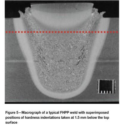
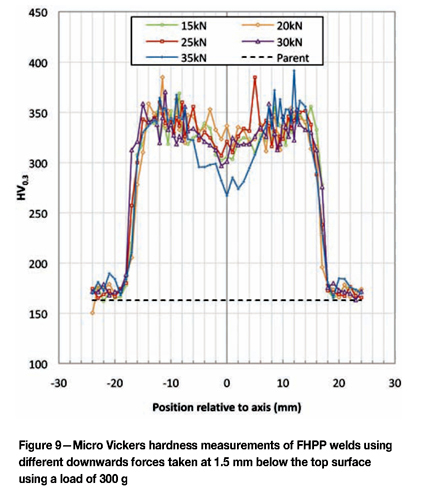
After welds 1-5 were completed, the samples were sectioned vertically through the axis and etched with 2% Nital for microstructural and microhardness analysis. Figure 5 shows a typical FHPP weld, and also depicts the positions of hardness measurements taken at 1.5 mm below the top surface in accordance with EN 104317, which specifies that the hardness of a fusion weld should be measured within 2 mm of the top surface.
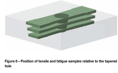
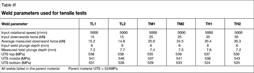
Tensile and fatigue samples were also removed from identical weld blocks by machining horizontal slices through the weld (Figure 6). These samples were taken from the same positions relative to the top surface as the temperature measurement positions, where the top, centre, and bottom samples correspond to the thermocouples at 2.5, 11.5, and 20.5 mm respectively. Tables III and IV show summaries of the tensile and fatigue test results respectively. The entire horizontal cross-section of the weld nugget is contained in each sample with ligaments on each side so that the final reduced section width is 1.25 times the original hole diameter before welding. The rationale behind the sample configurations was to test how an FHPP weld would perform as a part of structure surrounded by supporting material. Unfortunately, no equipment was available with the capacity to test the entire weld, whereas separate samples would allow for ligaments on either side of the weld nugget with a constant width ratio to the original hole diameter. Weld strength comparisons was then made at different depths so that weaker regions could be identified. It is generally considered that FHPP welds are axis-symmetrical12. However it has been found by the authors that this is not always the case, and this will be discussed in the following section. Therefore, testing of FHPP welds without including the entire weld nugget may distort results somewhat due to the localized appearance of defects. This is especially true of fatigue samples, where the occurrence of relatively small defects can have a significant impact on fatigue lifetimes.
Results and discussion
Weld macrostructure and hardness
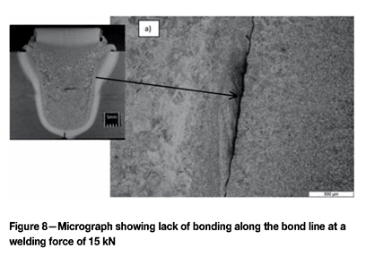
Figure 7 shows the flash formations of welds 1, 2, 3, and 5 (15, 20, 25 and 35kN downwards force respectively). It can be seen that the flash formations of these welds are not axis-symmetrical. Whether this is due to the high contents of alloying elements such as molybdenum, which increases the flow stress at elevated temperature, or geometry such as taper angles, is not clear. There was a lack of secondary flash features, as indicated by arrows in Figure 7a-c, which are linked to the occurrence of lack of bonding. These features, however, are somewhat mitigated by using higher downward forces. At 15 kN there are regions of almost no secondary flash (Figure 7a). The amount of secondary flash increased with increase in downward force at 20 kN and 25 kN respectively (Figures 7b and c). At 35 kN, the secondary flash is significantly more axis-symmetrical (Figure 7d). The formation of secondary flash is linked to the degree of contact between the plasticized stud material and the tapered hole wall, which in turn affects bonding12. The localized lack of secondary flash at 15 kN appeared to correspond to sites of significant lack of bonding two-thirds up the side of the original hole, as shown in Figure 8. Therefore, in contrast to welds performed on AISI 4140 steel which exhibited good bonding at around 10kN for a similar geometry6, it appears that FHPP of 10CrMo910 requires higher downward forces.
Changes in downward force, however, do not appear to have had any significant effect on the hardness of FHPP welds in 10CrMo910 (Figure 9), which is in contrast to FHPP welds conducted on AISI 4140 steel. AISI 4140 is a highly hardenable type of steel with high amounts of carbon, whereas 10CrMo910 is a high-strength low-alloy steel which does not harden to the same degree. With FHPP welding of AISI 4140 it was observed that increasing the downward force produced higher hardness values6. The drop in hardness of the 35 kN weld (weld 5) at the centre is indicative only of a smaller HAZ due to a low energy input.
Torque and temperature data
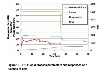
The process parameters and responses of a typical FHPP weld are shown in Figure 10. The downward force and rotational speed are controlled until the set plunge depth is reached, while the torque is a process response which is influenced by downward force, rotational speed, weld geometry, and welding materials. Once rotation stops, a forging force is applied to consolidate the plasticized material. Figure 11 shows the maximum process torque responses measured at 100 Hz during welding as a function of the average downward forces for a number of test welds. This excludes the touchdown torque (1st stage) and the ramp-down torque as rotation stops. Increasing the downward force progressively from 15 kN to 35 kN produced an increase in process torque, which is consistent with other research conducted on FHPP6; however, this seems to taper off at ~35 kN. Also, the general trend of the torque responses was similar to those reported6,12. Hattingh et al.6 reported that the torque responses of tapered FHPP welds consist of three main stages: a heating dominated phase, a heat-shear transition phase, and finally a shear dominated phase. In the heating dominated phase torque rises to a peak value, the torque then starts to decrease with periodic drops during the heat-shear transition phase until a more steady state is reached, called the shear dominated phase, where the torque gradually decreases until the weld is complete. An additional touchdown torque is observed at this high sampling rate, which is also reported with friction welding of round bars (termed 1st stage torque18). Here rubbing of the contact area progresses across the interface until the both surfaces are in complete contact with each other, causing a spike in the torque.
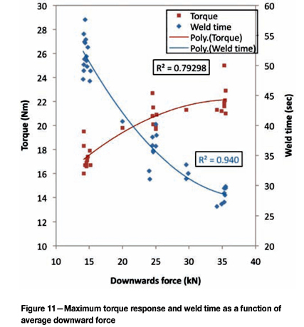
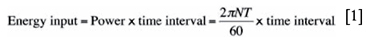
The torque responses and rotational speeds can also be used to approximate the energy input during FHPP welding, by using a generic power formula to calculate the energy input for a specific time interval and summing the total input (Equation [1]).The average energy input for the weld can be calculated using Equation [2]. The total energy input and average energy input of some of the tests are shown in Table II. Although the average energy input rate increases with downward force, the total energy decreases due to the shorter weld times. Figure 11 also shows the weld time as a function of the average downwards force. The higher the downward force, the shorter the weld time, which is consistent with welds performed by Meyer7.
where
Energy input (J)
Power (J/sec)
Time interval (sec)
N = rotational speed (r/min)
T = process torque (Nm)

where
Energy input rate (J/sec)
Energy input (J)
Weld time (s)
Individually, the average downward force had an effect on the total energy input as discussed above, but this does not give the full picture. The time taken for the weld to complete was also a variable which differed between otherwise identical welds and hence had an effect on the total energy input as shown in Equation [3]. This may have been due to differences in stud material and the consequent shear and flow dynamics of each individual weld. Therefore, by measuring the torque response and weld time, the total energy input could be more accurately determined than by just measuring the downward force.
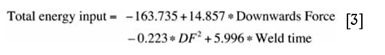
Where
Total energy input (kJ)
Downward force (kN)
Weld time (s)
Downward force has also been shown to influence temperatures around the weld interface as shown in Figure 12. The highest recorded temperatures were at the top and bottom positions (designated 2.5 mm and 27.5 mm respectively) which were very similar in magnitude and response. At 15 kN the temperatures were low, between around 898°C and 963°C. This significant variation between otherwise identical welds may have been due to the localized flash formation as shown in Figure 7. This is expected due to a relatively low energy input rate, as discussed and shown in Table II. The temperature increased to a maximum of approx. 1000°C at approx. 25kN and thereafter dropped to approx. 930°C at 35 kN. The lower temperature at the bottom position (27.5 mm) was likely due to the shear interface moving more rapidly away from the bottom of the hole, whereas at the top position (27.5 mm) the weld consolidated more rapidly, allowing less time for heat build-up and conduction. At 20.5 mm below the top surface, there appears to be a similar trend to the top and bottom positions, less pronounced.
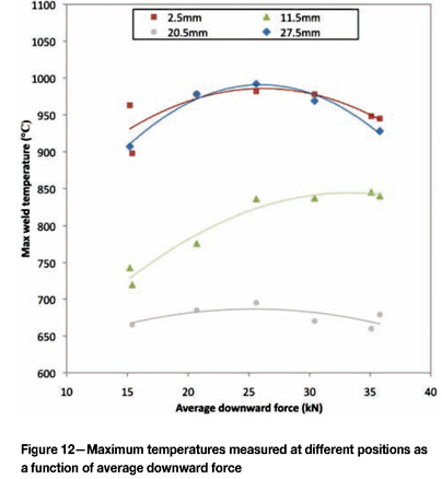
The largest variation in temperature response was at 11.5 mm below the top surface with the lowest temperatures at 15 kN. The temperature increased steeply with increase in downward force up to 25 kN and tapered off between 25 kN and 35 kN. At 11.5 mm and 15 kN, the low temperatures also correspond to defects discussed above (Figure 8). It appears that at approx. 15 kN and 20 kN(11.5 mm), there is insufficient heat build-up and consolidation between the plasticized stud material and the parent material around the hole, which caused a lack of bonding between the streams of material.
Tensile and fatigue data
Despite the significant lack of bonding shown on welds performed at 15 kN as shown in Figure 8, all samples failed in the parent material. This was surprising considering the extent to which the welded joint was compromised by such defects. This may, however, be explained by the large increase in tensile strength of the weld metal as shown by the high hardness values in Figure 9. Also, the weld was very rigid, as very little deformation occurred during tensile testing. The high stiffness of the weld nugget appears to protect it from deformation during loading, preventing cracks from propagating further along the bond line and causing failure. This, however, may not be the case with PWHT welds, where the stiffness maybe reduced so these low downward forces should be avoided.
These defects, however, did little to protect the welded joint during cyclical loading. Figure 13 shows the dynamic performances of the samples as a function of downward force. At the top position the lifetimes were relatively steady between 15 kN and 25 kN and increased slightly up to 35 kN. At the centre position, lifetimes increased steeply between 15 kN and 25 kN and were relatively constant up to 35 kN.
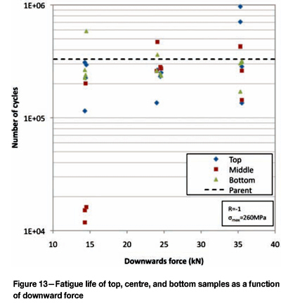
At 15kN the lifetimes of the centre samples were severely shortened. Lack of bonding defects situated along the bond line created multiple crack initiation sites, which then propagated along the length of the bond line until the joint was finally compromised, as shown in Figure 14a. This corresponded with the low temperatures measured at 15 kN at the 11.5 mm thermocouple position, which indicates a lack of consolidation between the plasticized stud material and the tapered hole wall, as shown in Figure 12. The bottom samples did not show any appreciable deviation with downward force between 15 kN and 35 kN and all failed in the parent material.
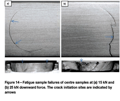
Of the 36 FHPP fatigue samples, 29 failed in the parent material region, on either side of the FHPP joint. Only one sample showed a crack initiation from the edge of the FHPP weld and the associated HAZ. Although all samples contained the weld nugget in the width of the sample, the HAZ was exposed at the outer edge. This would appear to demonstrate that the HAZ material was fairly resistant to crack propagation by fatigue. In two centre positioned samples at 25 kN and 35 kN (FM4 and FH2 respectively) cracks propagated through the weld nugget on the surface of the sample, as shown in Figure 14b. However, the lifetimes were not greatly affected and still fell within the range experienced for parent metal failures. Although in these centre samples cracks initiated from surface features, in reality these features were internal and therefore should not be so detrimental. Overall, the dynamic performances of all samples using a downward force below approx. 25 kN were inferior, so this range of is not recommended. Downward forces between 25 kN and 35 kN generally showed lifetimes similar to the parent metal samples, albeit with a greater scatter, which may be due to the stiffness of the weld nugget affecting the stress distribution across the sample. Therefore, downward forces in this range are recommended.
Conclusion
This paper investigated the effect of downward force on the static and dynamic performance of 10CrMo910 FHPP welds. The following conclusions can be drawn from the work.
- The formation of secondary flash was linked to the occurrence of localized defects along the bond line situated at some two-thirds from the bottom of the weld. This was found to occur at about 15 kN downward force
- Downward force had little effect on the hardness of the weld nugget and HAZ of 10CrMo910 steel, as opposed to AISI 4140 steel which exhibits higher hardness values at higher downward forces6
- The maximum process torque response increases with increase in downward force. Torque followed similar trends to that of AISI 4140 steel6
- Using higher downward forces increased the energy input rate but decreased the total energy input due to shorter weld times. The total energy input could be accurately determined by measuring the downward force and weld time
- Downward force had an effect on process temperatures achieved around the weld. At 2.5, 20.5, and 27.5 mm below the surface, the temperature was the highest at approx. 25 kN. At 11.5 mm below the sample surface, temperature increased with force up to approx. 25 kN, after which increasing the force has less of an effect
- Despite the occurrence of lack of bonding defects along the join line at 15 kN, downward force had no discernible effect on the structural strength of FHPP joints. All tensile samples failed in the parent material. This is likely due to strengthening and an increase in stiffness of the weld material
- Downward force had the greatest effect on the centre samples with significantly lower lifetimes at around 15 kN, compared to those between 25 kN and 35 kN which gave similar lifetimes to that of the parent plate at all positions.
Acknowledgements
The authors would like to thank the following contributors for their generous financial and technical support: National Research Fund (NRF) IRDP, Technology and Human Resources for Industry Programme (THRIP), Nelson Mandela Metropolitan University (NMMU), Eskom Holdings, Eriger (Pty) Ltd.
References
1. Nonaka, I. Residual life evaluation and repair procedures for high temperature boiler piping. Operations Maintenance Materials Issue 2003, vol. 2, no. 1. pp. 1-14. http://www.ommi.co.uk. [ Links ]
2. Seliger, P. and Gampe, U. Life assessment of creep exposed components, new challenges for condition monitoring of 9Cr steels. OMMI, vol. 1-2, August 2002. pp. 2-14. [ Links ]
3. Wedderburn, I., Doubell, P., Hattingh, D.G., and Newby, M. Condition monitoring of high temperature, high stress components by means of core sampling and friction weld repair. 18th World Conference on Nondestructive Testing, Durban, South Africa, 16-20 April 2012. [ Links ]
4. Thomas, W. and Nicholas, D. Leading edge -friction hydro pillar processing. TWI Connect, June 1992. [ Links ]
5. Thomas, W. and Nicholas, D. On trial - a new thick plate joining technique. TWI Connect, April 1993. [ Links ]
6. Hattingh, D.G., Bulbring, D.L.H., Els-Botes, A., and James, M.N. Process parameter influence on performance of friction taper stud welds in AISI 4140. Materials and Design, vol. 32, February 2011. pp. 3421-3430. [ Links ]
7. Meyer, A. Friction hydro-pillar processing - bonding mechanism and properties. Masters dissertation. FakultâtfürMaschinenbau und Eletrotechnik der TechnischenUniversitatCarolo-Wilhelmina zu Braunschweig, 2003. [ Links ]
8. Perrett, J.C. and Sketchley, P.D. Hole repair in steel plate using friction taper plug welding - initial trials in air and underwater. TWI2007 Feb:15015-3.01/2006/1264.3. [ Links ]
9. Thomas, W. and Nicholas, D. The need for gas shielding - positive advantages for two friction processes. TWI Bulletin, September/October, 1997. pp. 84-8. [ Links ]
10. Van Zyl, C.A.A. Analysis and modelling of the temperature distribution during the friction taper stud welding of 10CrMo910. Masters Dissertation, Nelson Mandela Metropolitan University, 2008. [ Links ]
11. Hattingh, D.G., Newby, M., Steuwer, A., Wedderburn, I.N., Doubell, P., and James, M.N. Friction taper stud welding of creep resistant 10CrMo910 steel. TMSFriction Stir Weld Process-V, 2009. pp. 75-84. [ Links ]
12. Bulbring, D.L.H., Hattingh, D.G., and Els-Botes, A. Feasibility of coring and plugging dissimilar steel welds by using friction taper stud welding. International Friction Processing Seminar 2011. [ Links ]
13. Pinheiro, G.A. Local reinforcement of magnesium components by friction processing: determination of bonding mechanisms and assessment of joint properties. GKSS Report 2008/12, Geesthacht; 2008. ISSN 0344-9629. [ Links ]
14. Ambroziak, A. and Gul, B. Investigations of underwater FHPP for welding steel overlap joints. Archives of Civil and Mechanical Engineering, vol. 7, no. 2, 2007. pp. 67-76. [ Links ]
15. Andrews, R.E. and Mitchell, J.S. Underwater repair by friction stitch welding. Metals and Materials - Marine Technology, December 1990. pp. 796-7. [ Links ]
16. Electric Power Research Institute. The Grade 22 Handbook. 2-1/4Cr-1Mo, 10CrMo9 10, 622, STPA24; 2005 [ Links ]
17. British Standards Institution. BS EN1043-1:1996. Destructive tests on welds in metallic materials. Hardness testing - Part 1: Hardness test on arc welded joints. London, BSI, 1996. [ Links ]
18. Hasui, A. and Fukashima, S. On the torque in friction welding. Journal of the Japan Welding Society, vol. 44, no. 12, 1975. pp. 1005-1010. (in Japanese) [ Links ]
© The Southern African Institute of Mining and Metallurgy, 2013. ISSN2225-6253.
This paper was first presented at the, Ferrous and Base Metals Development Network Conference 2012, 15-17 October 2012, Mount Grace Country House and Spa, Magaliesburg, South Africa..

