


Servicios Personalizados
Articulo
 Inglés (pdf)
 Articulo en XML
 Referencias del artículo
Indicadores

Links relacionados
-
 Citado por Google
 -
 Similares en Google
Compartir

 Permalink
Journal of the Southern African Institute of Mining and Metallurgy
versión On-line ISSN 2411-9717
versión impresa ISSN 2225-6253
J. S. Afr. Inst. Min. Metall. vol.113 no.2 Johannesburg feb. 2013
The role of alloying elements in bainitic rail steels
A. KapitoI; W. StumpfII; M.J. PapoI
IAdvanced Materials Division, Mintek
IIDepartment of Materials Science and Metallurgical Engineering, University of Pretoria
SYNOPSIS
The formation of bainite in steel is dependent on the size of the casting, the heat treatment, and the alloying elements. It is difficult to obtain a fully bainitic microstructure in steels during heat treatment because of its close proximity to the martensite (α') reaction. The ferrite (α) and pearlite reactions in steels are also rapid and shield the bainite reaction. Alloying elements therefore need to be added to separate the bainite reaction. Boron (B) and molybdenum (Mo) are key elements added to bainitic steels because of their ability to retard the α reaction. Other elements used in the production of bainitic steels are silicon (Si), chromium (Cr), manganese (Mn), and titanium (Ti). In this paper we investigate the effect of alloying elements on the bainite reaction through the use of dilatometry. Dilatometry is a technique that determines phase transformations in the steel and through which continuous cooling transformation (CCT) curves can then be developed. Some initial results are presented of an ongoing study on the development of bainitic steels for railway wheel applications.
Keywords: pearlite, bainite, ferrite, martensite, rail, continuous cooling transformation (CCT), dilatometry.
Introduction
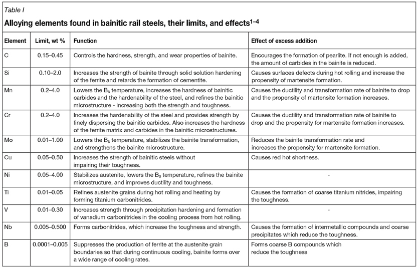
The alloying elements used to produce bainitic rail steels include carbon (C), silicon (Si), manganese (Mn), chromium (Cr), molybdenum (Mo), copper (Cu), nickel (Ni), titanium (Ti), vanadium (V), niobium (Nb), and boron (B)1-4. These alloying elements are added to retard the formation of pearlite and allow bainite to form during heat treatment. They also refine the austenite grain size, which in turn produces a fine bainitic microstructure, improving the toughness and strength of the steel. Other alloying elements increase the strength of the bainitic ferrite and refine the carbides. Most of the alloying elements lower the bainite start temperature (Bs), producing a finer, tougher, and stronger steel. Table I lists the limits usually added to bainitic rail steels, the function of each alloying element, and the effect of excess addition of each element to the steel.
Alloying elements that have received much attention in the development of the new-generation bainitic rail steels are B and Si. Si, if added in relatively large amounts (approximately 1-2 wt %), has the ability to hinder the formation of carbides in the bainitic microstructure1-4. This is significant in that the interlath cementite carbides in upper bainite embrittle the steel and act as crack initiation sites during rolling contact fatigue (RCF) loading. This has to a large extent hindered the commercial exploitation of bainitic rail steels2. When the carbides are supressed, a microstructure consisting of bainitic ferrite in a matrix of retained austenite and/or martensite is produced2.
Alloying elements also play a vital role in determining the microstructure of continuously cooled steels. Figure 1 shows a typical continuous cooling transformation (CCT) diagram for a conventional pearlitic rail steel.
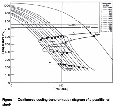
For a pearlitic rail steel, the bainite and pearlite regions overlap and in such steels the formation of bainite without pearlite is not possible. The martensite region is well below the bainitic or pearlitic regions but is still shielded by both reactions. However, the addition of suitable alloying elements can isolate the bainite region so that it can form without pearlite or martensite. Figure 2 is a typical CCT diagram for bainitic steel.
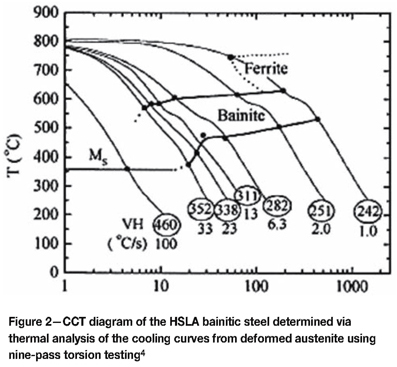
In Figure 2, the addition of alloying elements such as Mo and B pushes the pearlite and ferrite region to the far right, isolating the bainite reaction4,5. Boron forms a broad and flat bainite region, allowing for the formation of bainite over a wide range of cooling rates. For this effect to occur, the B has to be in solid solution and not bound to any oxygen within the steel. The addition of Ti or Al assists by scavenging the oxygen prior to the addition of B2,6.
In this paper, the effect of alloying elements on the microstructure of an experimental bainitic alloy is determined through the development of a partial CCT diagram.
Experimental procedure
Production of experimental bainitic alloy (BN1)
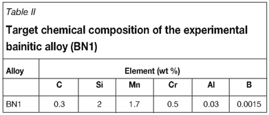
An experimental bainitic alloy (BN1) with a target composition shown in Table II was cast into a 15 kg ingot. BN1 is a medium-carbon steel with a C content of 0.3 wt %. A high Si content of 2 wt % was added to retard the formation of cementite (Fe3C) in the microstructure. Mn and Mo were added to improve hardenability and 15 ppm B, in the form of ferroboron, to retard the ferrite reaction and isolate the bainite reaction. An addition of 0.03 wt % Al was made to scavenge oxygen during casting and avoid gas porosity.
Dilatometry testing of experimental bainitic alloy (BN1)
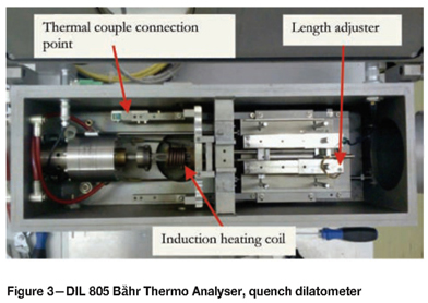
Specimens of 5 mm diameter by 10 mm length were machined from the as-cast alloy for dilatometer testing. A DIL 805 Bàhr Thermo Analyser quench dilatometer (Figure 3), which has the capability of heating and cooling test specimens in a vacuum or helium gas atmosphere, was used. The dilatometer is equipped with a digital data storage and output device which enables data to be stored and retrieved for analysis. The dilatometer had a programmable thermal cycle and continuously measured the specimen temperature and dimensional changes during testing. Dimensional changes were measured along the longitudinal axis, but temperature was measured at the mid-point of the test specimen length by a thermocouple welded to the surface of the specimen. The test specimen was heated inside an induction-heating coil.
The test samples were ground on 600 grit silicon carbide paper before the thermocouple was welded on. Each sample was heated at a rate of 0.5°C per second from 25°C to 950°C and held at that temperature for 15 minutes before cooling at different cooling rates. The cooling rates used to test BN1 were (°C per second): 30, 15, 7, 6, 4, 3, 2, 2.5, and 1. A separate test specimen was used for each heating/cooling cycle. After testing, each specimen was cross-sectioned transversely for microstructural analysis and hardness testing.
Microstructural analysis
The cross-sectioned specimens were mounted, polished, and etched with 2 per cent Nital (2 ml ethanol plus 98 ml H2O) to study the microstructure. In order to determine the cleanliness of the castings and distinguish the type of inclusions in the as-polished condition, scanning electron microscopy (SEM) was used. The inclusions in the as-cast microstructure were also quantified according to the ISO 4967 standard: Steel - determination of non-metallic inclusions - micrographic method using standard diagrams. Four 20 x 10 mm samples were analysed using a light microscope at 100X magnification. Micro-Vickers hardness tests were performed on cross-sections of the tested samples using a force of 9.81 N.
Results and discussion
Chemical composition
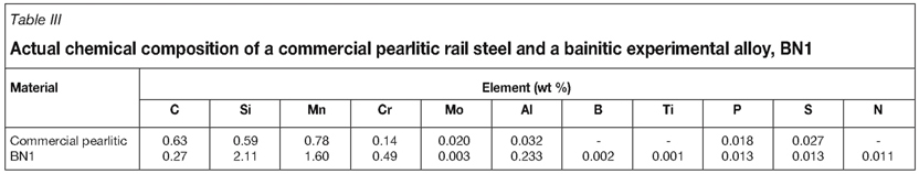
The chemical composition of the experimental bainitic alloy (BN1) is given in Table III. The chemical composition of a commercial pearlitic rail steel, obtained from SCAW Metals, is also given as a reference. BN1 contains C, Si, Mn, and Cr as major alloying elements, with B, Ti, N, and Mo as trace elements. Aluminium was deliberately added to scavenge oxygen and avoid porosity, but an Al content of 0.2 wt % (ten times higher than targeted) was obtained. This could negatively affect the mechanical properties of the alloy, such as toughness and strength, due to the formation of aluminium oxides. The presence of the aluminium oxides increases the amount of impurities in the steel and so reduces the cleanliness of the steel microstructure.
The inclusions as determined using the ISO 4967 standard were found to be Type D2, globular type oxides.
Dilatometer curves
Figure 4 shows a typical dilatometer plot obtained for BN1. Critical transformation temperatures were calculated at points where the slope of the curve deviated from linearity. To determine a critical temperature, a line was drawn vertically down from the slope, at the point of departure from linearity, to the temperature axis.
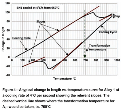
The test specimen contracted during isothermal holding at 950°C, as is indicated in Figure 4 by the uncharacteristically large gap between the heating and cooling cycles. This could be due to an instrument fault or inadequate holding time/temperatures. Nevertheless, the curves obtained still gave important data about the phase transformation behaviour of BN1 during cooling.
Microstructures of BN1 after dilatometry tests
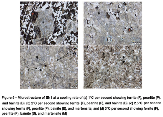
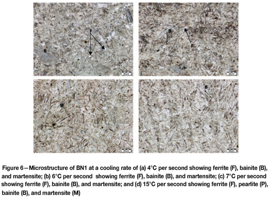
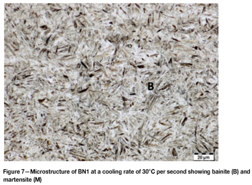
Figures 6-8 shows the microstructures obtained during dilatometer testing.
At 1°C per second BN1 had a pearlite-ferrite and bainitic microstructure. The amount of ferrite-pearlite diminished at faster cooling rates, while the amount of bainite increased. At a cooling rate of 3°C per second, the microstructure was predominantly bainitic with very little ferrite. At the cooling rates of 4-30°C per second, BN1 showed a microstructure consisting of bainite and martensite.
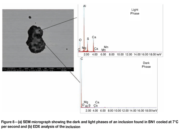
Scanning electron microscopy and energy-dispersive spectrometry
SEM was used to quantitatively analyse the inclusions observed in the as-polished condition in the microstructure of BN1. Three inclusions were analysed per cooling rate. The inclusions found consisted of light and dark phases, as shown in Figure 8. The light phase was found to be Al-rich and the dark phase was C-rich. The major elements in the inclusions were C, O, and Al. Other elements present included Si, sulphur (S), manganese (Mn), magnesium (Mg), and Cr. Calcium was present in all inclusions as a contaminant from the steelmaking process.
Continuous cooling curve (CCT) diagram for BN1
The critical temperatures derived from the change in length vs. temperature curves were plotted on a log-time vs. temperature diagram (Figure 9). The cooling rates and Vickers microhardness results are also shown.
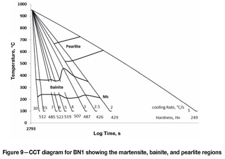
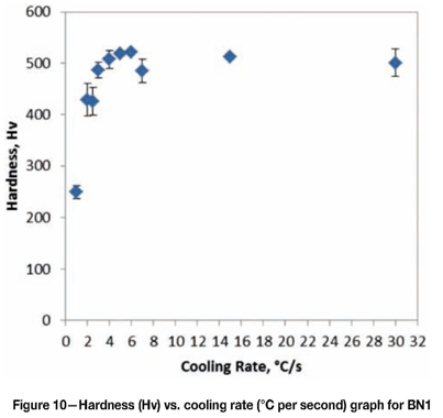
When compared to Figure 2, the CCT diagram for a pearlitic rail steel, the CCT diagram for BN1 shows the pearlite nose pushed to the right and the bainite reaction was isolated, broad, and flat. This indicates that the alloying additions chosen were sufficient in providing adequate hardenability to the steel. Bainite can be formed at cooling rates faster than 2.5°C per second without competing with the pearlite reaction. However, a completely bainitic microstructure is not possible during continuous cooling because the martensitic reaction occurs across all cooling rates. A completely bainitic microstructure would be possible only with isothermal heat treatment in the bainitic region. The addition of Ti could also expand the bainite region, thus favouring the formation of bainite instead of martensite. The hardness of the samples was between 426-523 Hv as shown in Figure 10. The hardness shows an increasing trend at the cooling rates between 2°C and 5°C per second. This is to be expected considering the amount of decreasing pearlite and increasing bainite between these cooling rates. At higher cooling rates the hardness is constant because the microstructure does not vary, and remains that of bainite and martensite.
Conclusions
The following conclusions can be drawn from the preliminary results obtained:
Pearlite was obtained in the microstructure at cooling rates 1-2.5°C per second
References
1. Kageyama, H., Ueda, M., and Sugino, K. Process for manufacturing high-strength bainitic steel rails with excellent rolling-contact fatigue resistance. US patent 5 382 307. 1995. [ Links ]
2. Bhadeshia, H.H.D.H. and Jerath, V. Improvements in and relating to carbide-free bainitic steels and methods of producing such steels. International Patent application WO 96/22396, published under the Patent Cooperation treaty (PCT). [ Links ]
3. Masahisa, F., Kazutaka, K., and Sadahiro. Y. High-strength, bainitic steel rail having excellent damage-resistance. US patent 5676772. 1997 [ Links ]
4. Ueda, M., Uchino, K., and Iwano, K. Bainite type rail excellent in surface fatigue damage resistance and wear resistance. Australian patent AU737977B2. 2001. [ Links ]
5. Steele, R.K. Steel alloys with lower bainite microstructures for use in railroad cars and track. US Department of Transportation Research and Special Programs Administration Final Report No. DOT-VNTSC-FRA-98-11. 2002. [ Links ]
6. Aglan, H.A., Liu, Z.Y., Hassan, M.F., and Fateh, M. Mechanical and fracture behavior of bainitic rail steel. Journal of Materials Processing Technology, vol. 151, 2004. pp. 268-274. [ Links ]
© The Southern African Institute of Mining and Metallurgy, 2013. ISSN2225-6253.
This paper was first presented at the, Ferrous and Base Metals Development Network Conference 2012, 15-17 October 2012, Mount Grace Country House and Spa, Magaliesburg, South Africa.

