


Serviços Personalizados
Artigo
 Inglês (pdf)
 Artigo em XML
 Referências do artigo
Indicadores

Links relacionados
-
 Citado por Google
 -
 Similares em Google
Compartilhar

 Permalink
Journal of the Southern African Institute of Mining and Metallurgy
versão On-line ISSN 2411-9717
versão impressa ISSN 2225-6253
J. S. Afr. Inst. Min. Metall. vol.112 no.11 Johannesburg Nov. 2012
Design and development of a novel thickener feedwell using computational fluid dynamics
T.V. NguyenI; J.B. FarrowII; J. SmithIII; P.D. FawellII
ICSIRO Mathematical and Information Sciences, Australia
IICSIRO Process Science and Engineering, Australia
IIIAnglo American Mineral Processing, South Africa
SYNOPSIS
The feedwell performance in gravity thickeners and clarifiers relies on the efficient mixing between solid particles and flocculant to achieve effective flocculation, as well as energy dissipation of the incoming feed stream. A population balance-computational fluid dynamics (PB-CFD) model has been developed and validated to provide new insights into the operation and performance of industrial feedwells. In particular, the PB-CFD model enables the efficacy of the main functions of a feedwell to be investigated for a wide range of feedwell designs and process conditions.
This paper describes how PB-CFD was used in the design and development of a new feedwell concept for the flocculation of particles in a solid-liquid stream. The patented feedwell design includes an upwardly converging flow diverter to create two separate compartments for energy dissipation and flocculation.
PB-CFD simulations of this simple and easy-to-retrofit feedwell design illustrate a superior performance in terms of flocculation and energy dissipation compared to typical feedwells over a wide range of flow conditions. The potential benefits include reduced flocculant consumption, better de-aeration, greater stability and the ability to cope with a wider variation in volumetric throughput, better flocculation and fines capture, and a more symmetrical discharge that may also offer improved overflow clarity in some applications.
The new feedwell design has been installed in a full-scale thickener at an Anglo American Platinum site in South Africa. A number of operational factors complicate this application, but indications are that the new feedwell has led to improvements in stability and underflow properties.
Keywords: thickener, feedwell design, flocculation, energy dissipation, computational fluid dynamics, simulation.
Introduction
Thickeners are a key unit in many hydrometallurgical processing operations for the separation of solids and liquor. Flocculant is often added to bridge the particles into large, fast-settling aggregates with the aim of producing a clear liquor overflow and a concentrated underflow suspension of solids. The overflow is usually collected from the outer edge of the upper surface of the thickener, and the thickened underflow is typically removed (by pumping) through a centrally located drain at the base of the thickener.
The nature of the flow structure in the feedwells is of critical importance to the performance of industrial thickeners, since it is generally here that most of the aggregation and energy dissipation processes occur. The flow inside the feedwell is turbulent, with the characteristics and distribution of the turbulence having a major influence on the way the flocculant mixes through the slurry, as well as on the particle aggregation processes and consequently the size and density of aggregates that are formed.
The feedwell should be designed to:
Dissipate the kinetic energy of the feed stream
As part of the AMIRA P266 'Improving Thickener Technology' series of projects (Fawell et al., 2009), a computational fluid dynamics (CFD) two-phase feedwell model was developed to investigate fluid flow, solids distribution, and flocculant adsorption (Johnston et al., 1998; Kahane et al., 2002). The model has been enhanced with the incorporation of population balance (PB) capability to account for aggregate growth and breakage processes, i.e. flocculation kinetics. The PB-CFD thickener model has been developed based on knowledge of the fundamental physical and chemical processes occurring within the feedwell, which has been gained from a comprehensive range of experimental measurements conducted on the laboratory, pilot scale, and full scale (Nguyen et al., 2006; Fawell et al., 2011).
The CFD model has been used to test and evaluate new feedwell design concepts and to provide performance comparisons with other common conventional designs. One such design concept is presented in this paper, along with an assessment of its full-scale implementation.
Modelling description
A conventional steady-state Eulerian-Eulerian two phase model is used as the basis for the PB-CFD feedwell model, with the standard k-ε turbulence model acting in the continuous phase. The phases share a common pressure field, with the momentum equations coupled via the interphase drag due to the liquid-particle slip. Implementation of the PB-CFD thickener model is in an ANSYS-CFX software package, with extensive use of additional customized FORTRAN subroutines to include the population balance and extra physics. Various details on the model equations and population balance descriptions have been given in previous publications (Nguyen et al., 2006; Mohanarangam et al., 2009).
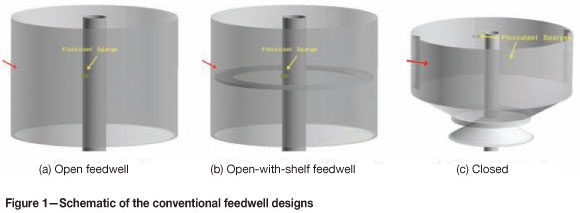
The PB-CFD thickener model is used to demonstrate the feedwell performance of a new feedwell design (termed the 'P266E feedwell') against the three common feedwell designs shown in Figure 1:
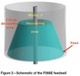
In the P266E feedwell design, shown in Figure 2, an upwardly converging cone is positioned on top of a small shelf inside the exterior feedwell shell, defining a first zone for energy dissipation (between the shell and cone) and a second zone for mixing and flocculation (between the cone and rake shaft). The single feed inlet is located at the bottom of the first zone, just above the shelf, so that the feed stream is forced to flow upward as a swirling flow in the first zone, providing an opportunity for de-aeration. The flow continues to circulate in the first zone above the top of the cone, dissipating energy before proceeding through the opening between the first and second zones. Flocculant can be introduced at the entry to the second zone so that the aggregates formed in this area will continue to grow undisrupted prior to exiting the feedwell.
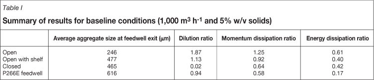
A standard set of process conditions (feed rate of 1 000 m3 h-1 and 5% w/v solids with a 20 g t-1 flocculant dosage) was used as the baseline to illustrate the insight and understanding of various aspects of feedwell performance using the calculated quantities outlined in the following section. The slurry was calcite (Omyacarb 20, d50 approximately 24 µm) and the flocculant was a 30 per cent anionic acrylamide/acrylate copolymer flocculant with high molecular weight.
Results and discussion
Performance indicators
From the PB-CFD model output, a number of parameters or performance indicators were calculated and used to evaluate the performance of the four feedwell designs. They are:
► Average aggregate size at the feedwell exit - used to indicate the size of the aggregates leaving the feedwell. This is used as a measure of the overall flocculation performance
Dilution ratio or recycle ratio, which is defined as the volume of fluid being recycled from the settling zone back into the feedwell (natural dilution) divided by the total volume of feed
Momentum dissipation ratio (MDR), defined as the ratio of the exit momentum of the fluid leaving the feedwell divided by the feed momentum entering the unit. It is calculated to show how much feed momentum is dissipated by the feedwell and/or generated by the action of gravity in the feedwell
Kinetic energy ratio (EDR), defined as the ratio of kinetic energy of the fluid leaving the feedwell divided by the total kinetic energy entering the unit. It is calculated to reflect the effectiveness with which the feed stream kinetic energy is dissipated by the feedwell
Maximum shear rate at the feedwell exit is usually an indication of the level of aggregate breakage at the exit. If this value exceeds 150 S-1, significant breakage of the flocculated aggregates would be expected.
Feedwell performance
Residence time
Feed particles need only a short period of time to flocculate and grow to large sizes after coming into contact with flocculant, usually less than 10 seconds in a reasonably well mixed feedwell. However, in order to dissipate its initial energy, the feed stream has to spend a lot longer inside the feedwell. One of the main features of the P266E feedwell is the length of time a feed particle spends without contacting flocculant, swirling around and up the inverted cone (Figure 3) and dissipating the initial energy along its path This is estimated from the CFD modelling as being approximately 30 seconds. Once coming into contact with the flocculant (just inside the truncated inner cone), there is only a short residence time (approximately 10 seconds) before the flocculated particles swirl down and out of the feedwell and into a region of lower shear within the bulk of the thickener.
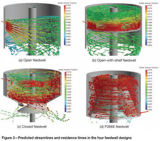
Conventional feedwell designs provide a very wide range of residence times, from very short (open feedwell) to medium (open-with-shelf feedwell) and long (closed feedwell), but the time periods required for energy dissipation and aggregation are not separated and are usually indistinguishable.
Energy dissipation, discharge characteristics, and feed dilution
A key function of any feedwell is the ability to dissipate the feed energy and momentum. The feed usually enters the feedwell with high levels of energy and turbulence, creating a region of very high shear downstream of the feed inlet. An efficient feedwell is one that utilizes this initial energy to promote mixing, solids/flocculant dispersion, and feed dilution for flocculation and fines capture, and then (at the very end) a gentle and uniform discharge flow at the feedwell exit. An uneven discharge flow with high velocities has severe implications in terms of short-circuiting and bed scouring, which can significantly impact on throughput, underflow density, rake torque, and overflow clarity.
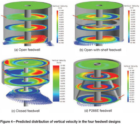
The flow structure of the four feedwells is shown in Figure 4 in terms of the vertical velocity distributions. It can be seen that the conventional feedwells range from uneven discharge with high velocities (open feedwell), uneven discharge with low-to-medium velocities (open-with-shelf), to reasonably even, although still somewhat asymmetric discharge with high velocities (closed). In comparison, the P266E feedwell is predicted to exhibit near symmetric discharge behaviour around the outer rim of the feedwell (with an inner rising dilution flow - discussed further).
Feed dilution is essential in operations where the feed solids concentrations are too high for effective flocculation and hence thickener throughput. Dilution can be achieved through several different means; it can be by pre-feedwell dilutione.g. E-Duc, or use of pumps to add additional liquoror by the utilization of dilution slots or natural dilution (recycle) inside the feedwell. The latter flows are usually inconsistent, unreliable, and insufficient to achieve the level of solids dilution required, and are not always delivered into the appropriate regions to benefit flocculation, i.e. dilution of the solids must occur before contact with the flocculant.
As an example of the potential for effective dilution, the velocity vectors plotted in Figure 5 for the P266E feedwell show a strong and continuous dilution stream, recirculating clear liquor from below back into the feedwell. How effectively this is utilized then depends on the flocculant sparge location, which in this case should be near the top of the cone section. While effective, this design can achieve only approximately a 1:1 (i.e. 50 per cent) dilution of the feed solids. If greater dilution is required, then this would need to be done external to the feedwell.
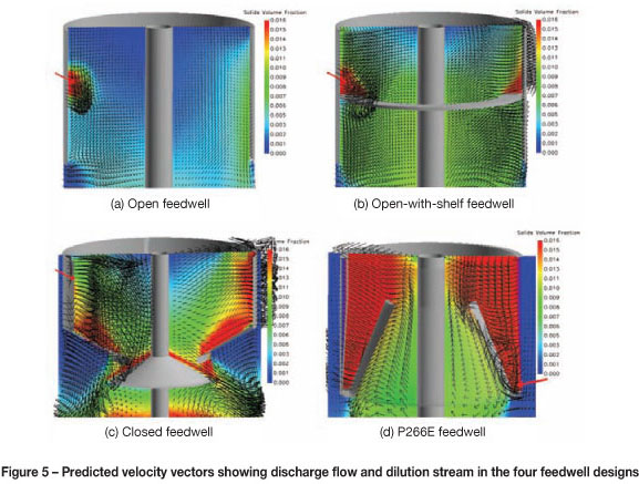
Natural dilution or recycle in conventional feedwells varies enormously, ranging from very little (closed feedwell), low-to-medium (open-with-shelf), to quite large (open). In the case of the open feedwell, the high-dilution flow is usually delivered into regions away from the feed solids and is not beneficial to the flocculation process. A further comparison of the performance of the four feedwell designs is given in Table I for the baseline conditions.
Shear regime, mixing, and dispersion
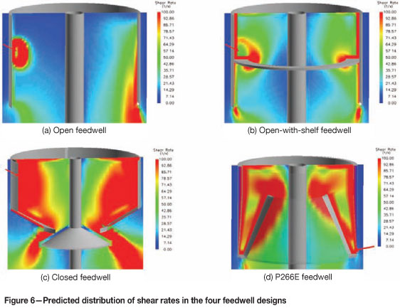
Shear and its distribution inside the feedwell plays a critical role in the aggregation process, with higher shear rates increasing the rates of flocculant mixing/adsorption, particle-particle collision, and aggregate growth. However, excessive shear will produce a high rate of aggregate breakage. In the flocculation process, it is preferable that the aggregates, when in contact with the flocculant, are formed in a medium shear region (usually between 50-150 S-1). To keep the aggregates growing undisrupted and to minimize the breakage phase, the shear rate along their paths within the feedwell should be maintained within this range.
Figure 6 illustrates the appropriate shear regime within the P266E feedwell, where the higher shear regions (between the inner truncated cone and the cylinder wall) are needed to provide mixing and solids dispersion. This is followed by a medium shear region (above and inside the inner truncated cone) for efficient continuous aggregation through the flocculation process. This sequence, high-medium-low, in shear distribution is critical to achieving efficient aggregation, but not often realized in common conventional feedwell designs.
Flocculant injection strategy
The location of the flocculant injection point is very important for achieving good flocculation performance from a feedwell. If the location is in a high shear region, the growth of the aggregates is severely affected by a corresponding high rate of breakage, with much of the flocculant thereby wasted. In a low shear region, the particle-particle collision rate is low, due to poor solids/flocculant dispersion. Local overdosing is a problem if the flocculant is injected into a high solids region, while aggregation is limited if it is introduced into a low solids region. Ideally, the flocculant should be injected into regions in the feedwell where the shear is reasonable (50-150 s-1) and the solids concentrations are within an appropriate range, say approximately 3-5% w/v (although this may be lower for clay-based tailings or very fine materials).
The flocculant injection strategy in the P266E feedwell follows these rules, with flocculant introduced by a single sparge to the top of the optimal flocculation region, which extends from above the top of the inner truncated cone to the feedwell exit (Figure 7). Within this favourable shear regime, the aggregation process is highly efficient, as the flocculant is thoroughly mixed in and fully adsorbed by the feed solids.
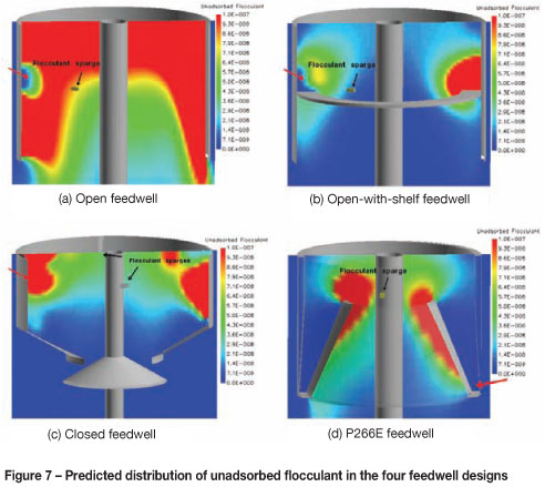
In most conventional feedwells, a simple and efficient flocculant injection strategy can be difficult to achieve, as the feed can split after entering and take quite different paths around the feedwell. Some streams may short-circuit; some may fall off a shelf, thereby leaving the feedwell quickly; while other streams still maintain a significant horizontal velocity component and are discharged much later. In the open feedwell, the flocculant is poorly adsorbed and the amount of unadsorbed flocculant leaving the feedwell is quite high, whereas in the open-with-shelf and closed feedwells the flocculant is essentially adsorbed by the solids, and very little unadsorbed flocculant is left at the feedwell exit.
Feedwell design features for scaling environments
In operations where scaling is an issue, an appropriate feedwell is one that has no dead zone or slow-moving slurry adjacent to the internal walls of the feedwell. The performance of the feedwell may be compromised by scale formation (which could change the flow patterns) and maintenance may be costly.
Plots of velocity distribution showing the velocity magnitude adjacent to the surfaces inside the feedwells are presented in Figure 8. It can be seen that the open feedwell has high shear only along the internal feedwell walls close to the feed inlet (see red region in Figure 8a). The open-with-shelf feedwell has high shear along the internal walls above the shelf, but low shear below the shelf (Figure 8b). The closed feedwell largely has high shear along the internal walls throughout the feedwell, but there are some regions where the shear is only moderate due to the presence of the vertical baffles. In contrast, the P266E feedwell has high levels of shear along the entire internal surface of the cylindrical section, as well as the external wall of the truncated inner cone. Based upon these shear rate profiles, the P266E feedwell would be expected to have the lowest scaling rate of these four feedwell designs.
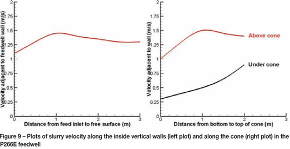
The slurry velocities adjacent to the inside cylindrical wall and along the wall of the truncated inner cone in the P266E feedwell are plotted in Figure 9 for a radial position 180° downstream of the feed inlet. It can be seen that the velocity from the base to the free surface (a length of 3 m) varies from 1.1 to 1.5 m s-1, but is generally fairly uniform. Likewise, the velocity along the external wall of the truncated inner cone, i.e. above the cone, also varies from 1.0 to 1.5 m s-1. Within the truncated inner cone the wall velocity is lower, decreasing from about 0.9 to 0.3 m s-1 from the top to the base of the cone. As indicated above, the high levels of turbulence along these regions of the P266E feedwell would be expected to result in a lower scaling rate compared to other feedwell designs.
De-aeration of the feed stream
The presence of air within a feed will always have a detrimental impact upon thickener performance, especially when the feed comes from a flotation circuit. If the level of entrained air is excessive then de-aeration prior to the thickener will be required. However, it is also important that a feedwell is designed to minimize the impact of any entrained air. The P266E feedwell takes this into account, with the design resulting in all of the slurry initially rising as it swirls around the external wall of the truncated inner cone and then entering a region of swirling flow extending from the cone to the free surface. This flow pattern is considered advantageous for air disengagement, allowing any bubbles to rise to the free surface. Importantly, these flow conditions occur prior to contact with flocculant, and therefore significantly reduce the likelihood of air being incorporated within aggregates (often a cause of solids carryover to the overflow).
Aggregation and feedwell design adaptability
The aggregation process as achieved by a feedwell encapsulates the performance of the various functions discussed in the previous section. If conditions are appropriate for flocculation, i.e. sufficient residence time, reasonable shear, good solid/flocculant dispersion and mixing, optimal solids concentrations, and appropriate flocculant injection strategy, then aggregation will be both effective (large aggregates and good settling) and efficient (good fines capture, low overflow solids, and low flocculant consumption). More effective flocculation has the potential to also influence underflow density and rake torque, as achieving the same settling rate at a lower flocculant dosage can lead to improved bed compaction or a lower bed yield stress.
Above all else, the P266E feedwell design was developed with the aggregation process in mind. The PB-CFD prediction of aggregate size and streamlines for the P266E feedwell shows aggregates starting to form after coming into contact with the flocculant in the flocculating region, then continuing to grow to large sizes as they are discharged into the settling zone below the feedwell (Figure 10d).
In the open feedwell (Figure 10a), aggregation is very limited as most of the feed sinks down and out of the feedwell without any contact with flocculant. The presence of an added shelf provides a good swirling flow in the top half of the feedwell (Figure 10b) but aggregation is affected by the excessive shear in these regions. The flow inside the closed feedwell (Figure 10c) is highly swirling throughout the feedwell, providing excellent mixing and solids dispersion and large aggregates. However, high shear in the lower regions of the feedwell is detrimental to the aggregation performance.
For good fines capture, a feedwell must provide sufficient contact time between the flocculant and all fine particles in the feed. The P266E feedwell performs this function quite well, predicted by PB-CFD to discharge only 0.13 per cent of the feed as fine particles (or very small aggregates) less than 26 µm, compared to 0.3-4.6 per cent from conventional feedwells under equivalent operating conditions (these numbers should not be taken as absolute - rather they represent relative performance only). It is important to note that large aggregate sizes can be formed under conditions that lead to very poor fines capture, particularly when portions of the feed stream take distinct paths through the feedwell. The good utilization of the available volume within the P266E feedwell is predicted to ensure both effective and efficient flocculation under most conditions.
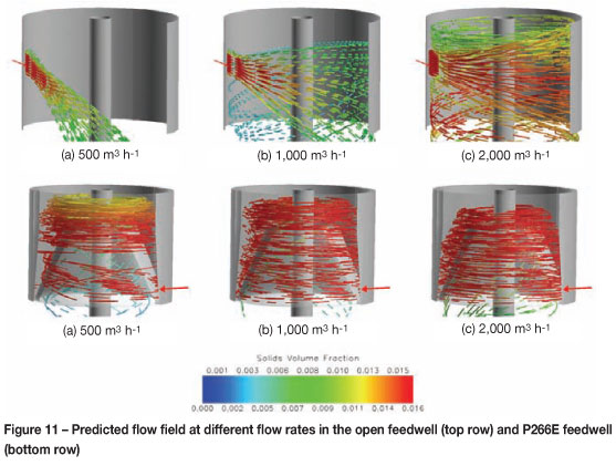
Adaptability to variable process conditions is highly desirable for a feedwell, although not readily achieved from conventional designs. An ideal feedwell should be able to cope with flow turndowns and future increases in throughput without any need for modification. At higher flow rates, a good feedwell design should have the ability to dissipate energy to avoid having excessive shear in the flocculating zone. When operated at lower flow rates or higher feed solids, it should be able to prevent the feed from short-circuiting, as well as provide sufficient mixing/dispersion and feed dilution.
One way for a feedwell design to achieve this is to produce a consistent flow field over the full range of process conditions, and this was certainly a goal of the P266E feedwell design. As shown in Figure 11, the predicted flow patterns inside the open feedwell vary widely over the range of flow rates modelled, whereas the flow patterns inside the P266E feedwell remain very similar with a strong swirling flow in the upflow and a gentle discharge flow.
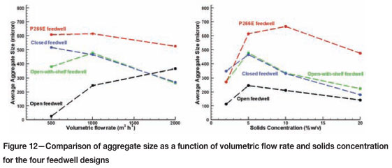
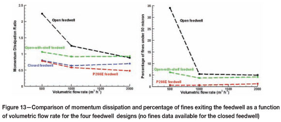
In Figure 12 the predicted average aggregate size is plotted against the volumetric flow rate and the solids concentration for the three conventional feedwells and the P266E feedwell. It needs to be remembered that the aggregation process is complicated by the interplay between various processes occurring in a feedwell under different process conditions, which include the shear regime, solids concentration, solids/flocculant dispersion, and feed dilution. The simulation results for the four feedwell designs show markedly different aggregate sizes over the range of process conditions considered. While the open feedwell produced the smallest predicted aggregate size, its performance improves at higher flow rates as a result of better feed retention and mixing. The open-with-shelf and the closed feedwell display very similar results over the range of process conditions. Notably, because of its consistent flow field, the P266E feedwell is predicted to produce very effective flocculation with much larger aggregate sizes compared to the other feedwells, for both changes in the feed flow rate or the feed solids concentration. Similarly, the P266E feedwell is predicted to have superior momentum dissipation and fines capture across a wide range of feed flow rates (Figure 13).
A further comparison of the performance of the four feedwell designs is given in Table I for the baseline conditions.
Installation of P266E feedwell
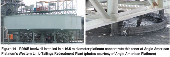
The first P266E feedwell design was installed at Anglo American Platinum's Western Limb Tailings Retreatment (WLTR) plant in December 2009. The feedwell and the truncated inner cone were manufactured offsite in two halves and simply bolted together onsite. Figure 14 shows the installed P266E feedwell (1.6 m diameter) in operation within a 16.5 m platinum concentrate thickener at WLTR. In this application the feed flow rate varied between 50-130 m3 h-1 (although most often was at the lower end of this range) with a feed solids concentration of approximately 17 wt%. Extra feed dilution is provided by four dilution slots located at the top of the feedwell. One particularly challenging operational issue was the large quantities of air being entrained as the feed slurry passed through a header tank.
Quantifying the performance of the installed feedwell is difficult, given the limited instrumentation on the thickener and the variability of the volumetric feed rate. After installation, the most obvious operational improvement was that the feedwell did not overflow, which had been a regular issue with the original feedwell. This may in part reflect the shorter depth of the P266E feedwell, with the old design at times likely to have been discharging beneath the bed surface, resulting in back-pressure. However, the expected greater capacity of the P266E feedwell to deal with variations in the feed's volumetric flow rate is also a likely factor. While the underflow density remained about the same or was only slightly increased, this was at a time when the particle size of the feed solids reduced significantly, with the d50 dropping from approximately 11 µm to approximately 7 µm after installation. The fact that the underflow density did not reduce as the particle size became finer supports better flocculation efficiency from the P266E feedwell. Flocculant consumption would normally rise significantly from a shift to a smaller particle size, but no such rise was observed, again consistent with better flocculation. Subsequent splitting of the flocculant dose between the feedpipe and the feedwell led to a reduction in applied dosage, which may also have benefited underflow density. It is expected that significantly better performance would be achieved if the very high levels of entrained air were eliminated from the thickener feed stream.
Conclusions
CFD modelling offers enormous potential for the optimization of thickener design, and with the high performance requirements expected of modern thickeners, the application of CFD to new and existing units will only increase. In this paper, CFD modelling has been used to provide insight and understanding of many features required of a feedwell. Apart from the two main feedwell functions; namely, momentum dissipation and flocculation, several other requirements and concepts have been identified and discussed.
Based on these new understandings and concepts, the CFD model was used to develop a novel feedwell design that reduces the shortcomings of conventional and common feedwell designs. Its performance was also assessed successfully against a number of performance criteria.
Acknowledgements
The authors thank the following sponsors of the P266F AMIRA P266 'Improving Thickener Technology' project for their support: Alcoa World Alumina, Alunorte, Anglo American, BASF, Bateman Engineering, BHP Billiton, Cytec Australia Holdings, Exxaro, FLSmidth Minerals, Freeport-McMoRan, Hatch Associates, Metso Minerals Process Technology, Nalco Company, Outotec, Rio Tinto, Rusal, Shell Energy Canada, Teck Resources, Total E&P Canada, and WesTech.
The direct involvement and contributions from numerous industry personnel has been crucial to the success of this work. The authors also wish to acknowledge the contributions from a wide range of CSIRO staff.
The authors would also like to thank Anglo American Platinum for their contributions towards the installation of the P266E feedwell at the WLTR plant and their permission to include associated details in this paper.
References
FAWELL, P.D., FARROW, J.B., HEATH, A.R., NGUYEN, T.V., OWEN, A.T., PATERSON, D., RUDMAN, M., SCALES, P.J., SIMIC, K., STEPHENS, D.W., SWIFT, J.D., AND USHER, S.P. 2009. 20 years of AMIRA P266 'Improving Thickener Technology' -how has it changed the understanding of thickener performance? Paste09. Proceedings of the 12th International Seminar on Paste and Thickened Tailings, Vina Del Mar, Chile, 21-24 April 2009. Jewell, R.J., Fourie, A.B., Barrera, S., and Wiertz, J. (eds.). Gecamin Limited, Santiago; Australian Centre for Geomechanics, Perth. pp. 59-68. [ Links ]
FAWELL, P.D., SIMIC, K., MOHANARANGAM, K., STEPHENS, D.W., RUDMAN, M., PATERSON, D., YANG, W., AND FARROW, J.B. 2011. Pilot and full-scale validation of thickener and feedwell modelling. Paste2011. Proceedings of the 14th International Seminar on Paste and Thickened Tailings, Perth, Australia, 5-7 April 2011. Jewell, R.J. and Fourie, A.B. (eds.). Australian Centrefor Geomechanics, Perth. pp. 81-91. [ Links ]
JOHNSTON, R.R.M., SCHWARZ, P., NEWMAN, M., KERSHAW, M., FARROW, J.B., SIMIC, K., AND SWIFT, J.D. 1998. Improving thickener performance at Pasminco Hobart Smelter. Zinc and Lead Processing. Dutrizac, J.E., Gonzalez, J.A., Bolton, G.L., and Hancock, P. (eds.). Canadian Institute of Mining, Metallurgy and Petroleum. pp. 697-713. [ Links ]
KAHANE, R.B., NGUYEN, T.V., AND SCHWARZ, M.P. 2002. CFD modelling of thickeners at Worsley Alumina Pty Ltd. Applied Mathematical Modelling, vol. 26, no. 2. pp. 281-296. [ Links ]
MOHANARANGAM, K., NGUYEN, T.V., AND STEPHENS, D.W. 2009. Evaluation of two-equation turbulence models in a laboratory-scale thickener feedwell. Seventh International Conference on Computational Fluid Dynamics in the Minerals and Process Industries, Melbourne, Australia, 9-11 December 2009. [ Links ]
NGUYEN, T.V., HEATH, A., AND WITT, P. 2006. Population balance - CFD modelling of fluid flow, solids distribution and flocculation in thickener feedwells. Proceedings of the Fifth International Conference on CFD in the Process Industries, Melbourne, Australia, December 2006. [ Links ]
© The Southern African Institute of Mining and Metallurgy, 2012.ISSN 2225-6253. This paper was first presented at the, 15th International Seminar on Paste and Thickened Tailings (Paste) 2012, 16-19 April 2012, Sun City, South Africa.

