


Serviços Personalizados
Artigo
 Inglês (pdf)
 Artigo em XML
 Referências do artigo
Indicadores

Links relacionados
-
 Citado por Google
 -
 Similares em Google
Compartilhar

 Permalink
Journal of the Southern African Institute of Mining and Metallurgy
versão On-line ISSN 2411-9717
versão impressa ISSN 2225-6253
J. S. Afr. Inst. Min. Metall. vol.112 no.2 Johannesburg Jan. 2012
JOURNAL PAPER
Fast, safe, and fully mechanized installation of high-tensile chain-link mesh for underground support
B. SchoevaertsI; C. BalgI; S. BrownII; C. Van ZylIII
IGeobrugg AG, Geohazard Solutions
IIRock, Australia
IIIGold Fields
SYNOPSIS
The ever-increasing depth of mineral extraction presents a challenging environment for hard-rock underground mines. High in situ stresses and associated seismicity with potential rockburst hazards are the major decisive factors contributing to the choice of a ground support regime.
Conventional ground support systems, designed primarily for static loads, are not always capable of providing safe working conditions for underground personnel in seismically active mines.
Systems specifically developed to resist dynamic loading and allowing for larger deformations are therefore preferred alternatives.
High-tensile chain-link mesh has a proven record of successful use in open cut operations in various rockfall barrier installations due to its high energy absorption capacity. It has also been used in underground operations in various parts of the world. Its application in South African underground mining, however, is limited due to the high labour intensity.
This paper describes a method of mechanized installation of a chain-link mesh as evaluation at Gold Fields' South Deep Gold Mine situated some 45 km south-west of Johannesburg.
A purpose-built mechanized roll mesh handler, developed in Australia, was used in this trial. The handler is compatible with all standard multi-boom underground drill rigs and is operated utilizing the hydraulic circuit normally used for the feed arrangement.
A number of key performance indicators have been specified as success criteria by Gold Fields:
A 30% faster installation compared to the conventional methodology
Although the energy-absorbing mesh combined with yielding rockbolts is a ground support system of choice for rockburst-prone conditions, the operational upsides recognized during the trial imply that this product can also be competitively used in less demanding ground conditions where weld mesh or shotcrete are customarily used as a primary surface support.
Keywords: underground support, rockburst, mesh handler, high-tensile chainlink mesh.
Introduction
Increasing stresses and associated seismicity with the risk of rockbursts is a serious challenge for deep hard-rock underground mines. Conventional ground support systems are not effective in rockburst conditions and thus have to be replaced by systems specifically designed for dynamic loading and large deformations. One of the ground support products used in rockbursting conditions is high-tensile chain-link mesh.
High-tensile steel wire mesh showed good performance in rockfall and rockburst testing. Due to its strength and flexibility, the mesh was able to absorb the kinetic energy thereby slowing down the impacting rock masses.
The high strength of the mesh is required to transfer the rockburst loads to the anchors and to avoid puncturing of the mesh by the rock fragments. Although its ability to withstand large rock mass deformations has been proven, its use in mines is limited due to the high labour intensity.
To use chain-link mesh as a standard product for ground support in mechanized mines, a safe and automated installation method had to be developed. The aim is to provide mine operators with an efficient and effective way to install rolled high-tensile chain-link mesh. Furthermore, it was considered desirable that the mesh handler should be capable of being retrofitted on all commonly used underground drilling equipment, thus obviating the purchase of new machines.
To test the practical aspects of such installation, a trial was organized at the Gold Fields South Deep, twin shaft. A purpose-built mechanized roll mesh handler developed in Australia was used in this trial.
High-tensile chain-link mesh for ground support
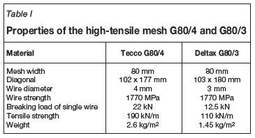
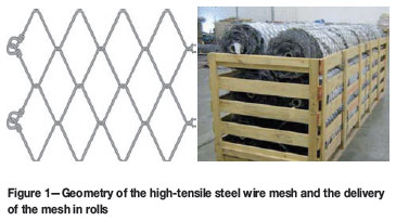
High-tensile wire mesh offers a surface support for most ground conditions. The mesh is made of high-tensile steel wire with a diameter of 4 or 3 mm and a tensile strength of 1 770 N/mm2. The mesh is diamond shaped, and along the edges the wires are bent over and double twisted such that this connection is as strong as the mesh, which is also proofed by independent test institutes. Both meshes are produced in rolls which reduce the storage space and can be manufactured in widths of up to 3.5 m and in tailor-made lengths corresponding to the tunnel surface.
Due to the use of high-tensile wire, the mesh is very light in relation with its strength (TECCO®: G80/4 2.6 kg/m2, DELTAX®: G80/3 1.45 kg/m2). For corrosion protection, the wires are coated with a special aluminum-zinc coating which has a higher corrosion resistance than standard galvanizing. Comparison tests with conventional galvanized wires yield at least a three to four times longer lifespan.
The MESHA® installation handler offers a fast and safe method of application of both the TECCO® and DELTAX® meshes and can be retrofitted to any multi-boom underground jumbo.
The mesh geometry was designed to have a very high breaking load as well as low deformation characteristics to avoid unacceptable deformation rates and unravelling of the rock after a rockburst impact. The resistance properties of the mesh were determined in a series of laboratory tests by Torres1 at the University of Cantabria in Santander, Spain. The properties of the meshes G80/4 and G80/3 are summarized in Table I.
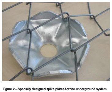
A specially designed spike plate has been developed by GEOBRUGG to transfer loads from the mesh through the spike plate to the anchoring system (Figure 2). The plates are made out of 5 mm thick galvanized steel and with a shape which best fits to the mesh. The spike plate grabs the mesh in six positions plus the rock bolt in the centre. Due to its threedimensional shape it is very stiff and does not bend.
Testing and modelling of high-tensile chain-link mesh
In order to determine the mechanical properties of the mesh, TECCO® was extensively tested for static and dynamic loading conditions, and DELTAX® was tested for static loading, at the Western Australian School of Mines (WASM). For the dimensioning of the support system consisting of mesh and bolts, a finite element numerical model was developed, calibrated, and verified by the Swiss Federal Research Institute (WSL).
Static testing
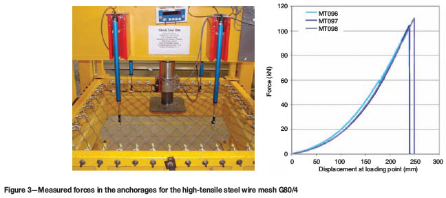
The static response of high-tensile chain-link mesh was determined by test work in the WASM laboratory in Kalgoorlie. Figure 3 shows the response of three samples of the high-tensile TECCO® G80/4 mesh where a 1.3 x 1.3 m panel was loaded with a 300 x 300 mm steel plate. The test setup is described by Morton et al.2 The high-tensile mesh was able to bear a load of up to 100 to 110 kN before it failed at the edge of the loading plate.
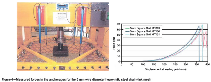
Weld mesh, in comparison, failed at approximately 40 kN, and mild steel chain-link failed at less than 20 kN using the same test setup. For the heavy mild steel chain-link mesh (5 mm diameter, mesh width 100 mm, tensile strength 460 N/mm2), failure occurred at 30 to 40 kN due to bending over of wires at the mesh ends (according to the test report by Villaes-cusa3). After closing the ends with wire rope clips (see Figure 4), rupture occurred at 60 to 70 kN. All mesh types require some initial displacement to be activated and loaded.
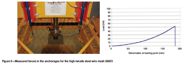
The high-tensile mesh G80/3 was able to bear a load of up to 50 kN before it failed at the edge of the loading plate (Figure 5).
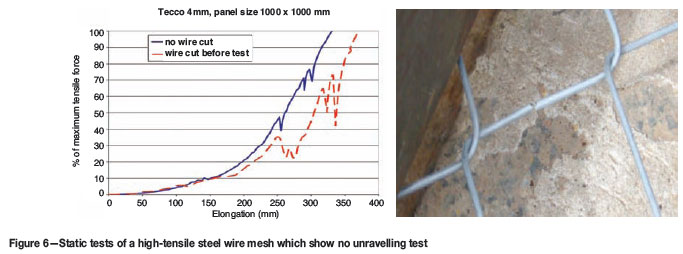
It was also found that the high-tensile chain-link mesh can sustain an increase in load even after a wire has failed. It also does not unravel once a wire has failed.
In earlier tests, the high-tensile mesh was tested in a way similar to an application underground with four bolts and plates. It was established in that test that rupture generally starts at the crossing points, but does not shear at the edge of the plates due to the higher steel quality of the mesh compared to the mild steel plates. Based on experiece with mild steel chain-link mesh, there was always the concern that if one of the chain-link mesh strands is broken, the mesh will unravel and open. It has been proven that this is not the case for high-tensile chain link mesh in the above-mentioned test, where the mesh was loaded with one of the wires cut.
The test results, capacity, and deformation of the high tensile chain-link mesh have been shown to be unaffected by the broken wire (Roth et al.4), and is shown in Figure 6. This applies only for high-tensile chain-link mesh. It does not apply for mild steel chain-link mesh, as the individual wire does not have the required strength to lock itself in.
Dynamic testing
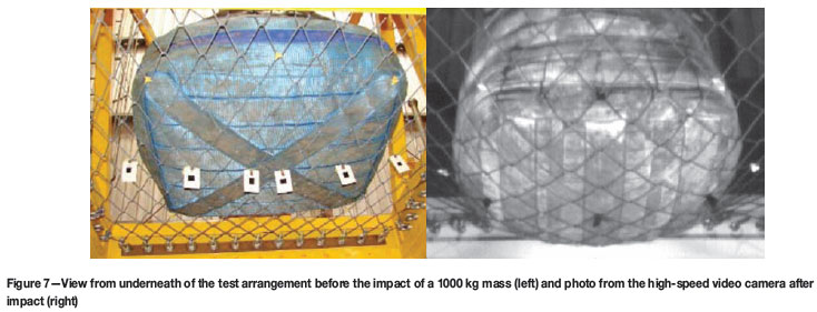
The G80/4 mesh was tested at the dynamic testing facility of WASM (Player et al.5) by using a momentum transfer method (see Player et al.6; Thompson et al.7). The mesh panel is installed in a loading frame and a steel weight can be dropped onto the mesh from different heights. The rebound of the loading frame is stopped by buffers while the loading mass impacts the mesh sample without separation.
This test arrangement simulates the situation with installed mesh in tunnels. The dynamic test apparatus is instrumented with high-speed video cameras, load cells, and accelerometers.
Figure 7 shows images from a camera and a high-speed video camera before and after a mass of 1 000 kg (bag with mill steel balls) hits the high-tensile chain-link mesh. The mesh deforms with the applied load and transfers the forces to the boundary. The boundary conditions are fixed to have comparable and repeatable results.
It was established that the high-tensile chain-link mesh G80/4 is able to absorb energies of up to 12 kJ in such a configuration. This is equal to stopping a rock mass of 1 000 kg that was accelerated to 4.9 m/s. This value represents the energy absorption of the mesh only, and does not include any absorption by the rock mass or the yielding bolts.
Welded wire mesh (wire diameter 5.6 mm and 100 mm wire spacing) showed energy absorption capacities up to 2 kJ in the same test setup.
Numerical model
For the numerical model, we sought an algorithm that was capable of handling large deformations and dynamic impacts. A code was chosen that is based on a discrete finite element method (FEM) and a model of rope and truss elements. In order to simulate dynamic impacts, Newton's second law is applied together with the material properties of the single components ('time-stepping'). The software FARO ('falling rock') was developed by the Swiss Federal Institute of Technology ETH and the Swiss Federal Research Institute WSL (Volkwein et al.8).
Figure 8a shows the static mesh tests executed by Roth et al.4 with the mesh and a bolt pattern of 1 x 1 m where the mesh was loaded with a steel frame. These tests were used to calibrate the numerical model. It became possible to perform dynamic simulations and assess forces, failure modes and deformations of the different components with the calibrated FEM model.
With the numerical model of a ground support system with high-tensile steel wire mesh, it is possible to simulate the dynamic response of any setup and loading. More precise information about FARO load modelling and different kind of possibilities for boundary modeling can be found in Volkwein.9 Input parameters can be adjusted to specific project parameters and the bolt pattern and maximum deflections can be determined.
This makes designed ground support schemes for dynamic loading theoretically possible. It is very important to have a support system where the support components have matching capacities. The calibrated numerical model makes it possible to connect different bolt types with the high-tensile steel wire mesh and determine if they work together under given conditions. Since there is always a load concentration on the bolt plates, higher loads could be achieved by using special plates able to grab more wires, like the spike plate shown in Figure 2.
Installation of high-tensile chain-link mesh underground
The difference between the installation of welded mesh and the installation of chain-linked mesh is due to the stiffness of the products. The welded wire mesh is relatively stiff and is delivered and applied in sheets. The roll of chain-link mesh is stiff only in one direction but flexible in the other, and therefore has to be installed in a different way to welded wire mesh.
Therefore a new method was conceived, comprising a mesh handler to unroll the mesh and hold it onto the surface of the tunnel while it is pinned to the rock with the second jumbo boom. The main objectives were the speed and safety of the installation in order to comply with the targets of modern mining both in terms of safety and economics.
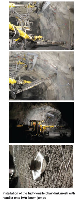
Fully mechanized installation of chain-link mesh with the MESHA® installation handler
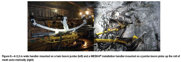
An automated roll mesh handler for the application of high tensile chain-link mesh was developed and successfully tested in Australia and Switzerland for the installation of support in underground workings. The handler, called MESHA® installation handler, is compatible with all standard multi-boom jumbo drilling equipment, and applies mesh from a cassette system. The handler with the mesh roll is on the one boom and the drill/bolter mounted on the other boom of the jumbo (Figure 9). The application of the high-tensile mesh and installation of split-sets or bolts occur simultaneously.
The handler is manipulated from the cabin of the drill to pick up a roll of TECCO® or DELTAX® mesh, minimizing manual handling. The mesh can then be positioned on the walls and backs for bolting, using the drilling component of the opposite boom.
The system reduces manual handling and personnel exposure during the installation process, reduces support cycle times, enables the mesh to follow the rock surface contours more closely-reducing unravelling/bagging of material in voids. No personnel are exposed to unsupported ground, due to the ability of the jumbo to pick up the mesh roll cassette with the manipulator arm.
In situ installation trial at Gold Fields South Deep, general experience
From the results obtained, the following comparison between conventional wire mesh installation and wire meshing using the MESHA® installation handler as well as DELTAX® wire mesh developed by GEOBRUGG could be formulated (Table II)
It was assumed that the MESHA® installation handler did not influence the drilling time. It is assumed that in future the same drilling pattern as the one used in conventional sheet meshing will be used. To ensure that the same support standards were used for sheet wire meshing and the MESHA® installation handler, it was included that 10 split sets be installed on either side of the sidewall, using the same method as for those installed in the hangingwall. The accuracy of the information may be limited by the following factors:
During the trial the operator stated that the MESHA® installation handler seemed to be more effective than conventional meshing and there was no damage noted to the Deltax® G80/3 mesh after blast.
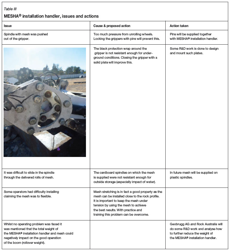
A number of issues have been raised, as listed in Table III together with proposed solutions and actions taken as a result of the trial.
Conclusions
After successfully testing the high-tensile chain-link mesh under both static and dynamic conditions, it was shown that this kind of mesh is suitable for ground support in potential rockburst areas and also in high-deformation ground conditions. In contrast to shotcrete or fibrecrete, the rock remains visible for inspection by geotechnical personnel. With the use of the MESHA® installation handler, this new type of mesh can be installed easily and more quickly than welded sheets of mesh.
It is evident that wire meshing contributes largely to the number of hours spent at the face and therefore, also the need for crews to spent time underground. This is unnecessary, as it is evident that a large amount of time can be saved, according to the key performance indicators pertaining to the MESHA® installation handler and the trial data obtained from the MESHA® installation handler. It can be concluded that both the high-tensile chain-link mesh and its fully mechanized installation can significantly increase the safety of mining personnel, the quality of the installed ground support, and the speed of mining development.
References
1. Torres. The resistance properties of the mesh were determined in a series of laboratory tests, University of Cantabria, Santander, Spain. [ Links ]
2. MORTON, E., THOMPSON, A., VILLAESCUSA, E. ,and ROTH, A. Testing and analysis of steel wire mesh for mining applications of rock surface support. ISRM Congress, Lisbon, Portugal. 2007. [ Links ]
3. VILLAESCUSA, E. Dynamic testing of ground support elements. M349A Quarterly Progress Report March 2009, Western Australian School of Mines, Kalgoorlie, Australia. 2009. [ Links ]
4. ROTH, A., WINDSOR, C., COXON, J., and DE VRIES, R. Performance assessment of high-tensile steel wire mesh for ground support under seismic conditions. Ground Support Symposium, Perth, Australia, 2004. pp. 589-594. [ Links ]
5. PLAYER, J., MORTON, E., THOMPSON, A. AND VILLAESCUSA, E. Static and dynamic testing of steel wire mesh for mining applications of rock surface support. The Sixth International Symposium on Ground Support in Mining and Civil Engineering Construction, Cape Town, South Africa, 2008. pp. 693-706. [ Links ]
6. PLAYER, J., VILLAESCUSA, E., and THOMPSON, A. Dynamic testing of rock reinforcement using the momentum transfer concept. Ground Support Symposium, Perth, Australia, 2004. pp. 327-339. [ Links ]
7. THOMPSON, A., PLAYER, J., and VILLAESCUSA, E. Simulation and analysis of dynamically loaded reinforcement systems. Ground Support Symposium, Perth, Australia, 2004. pp. 341-355. [ Links ]
8. VOLKWEIN, A., ANDERHEGGEN, E., and GRASSL, H. Numerical simulation of highly flexible rockfall protection systems. 5th World Congress on Computational Mechanics, Vienna, Austria, 2002. pp. 224-230. [ Links ]
9. VOLKWEIN, A. Numerical simulation of flexible rockfall protection systems. Doctoral dissertation Eidgenössische Technische Hochschule ETH, Zurich, Switzerland. 2004. [ Links ]
10. TONKIN, C.J. Time and Motion study of sheeted wire meshing and rolled wire meshing systems. Gold Fields South Deep. 2011. [ Links ]
This paper was first presented at the, MineSafe Conference, 15-18 August 2011, Emperors Palace, Hotel Casino Convention Resort, Johannesburg.
© The Southern African Institute of Mining and Metallurgy, 2012. SA ISSN 0038-223X/3.00 + 0.00.

