


Servicios Personalizados
Articulo
 Inglés (pdf)
 Articulo en XML
 Referencias del artículo
Indicadores

Links relacionados
-
 Citado por Google
 -
 Similares en Google
Compartir

 Permalink
Journal of the Southern African Institute of Mining and Metallurgy
versión On-line ISSN 2411-9717
versión impresa ISSN 2225-6253
J. S. Afr. Inst. Min. Metall. vol.112 no.2 Johannesburg ene. 2012
TRANSACTION PAPER
Managing the geotechnical and mining issues surrounding the extraction of small pillars at shallow depths at Xstrata Coal South Africa
S.Z. Pethö; C. Selai; D. Mashiyi; J.N. van der Merwe
Xstrata Coal South Africa
SYNOPSIS
Pillar extraction at shallow depths with small pillars that were not originally intended for secondary extraction can provide a huge benefit to the coal mining industry in those areas where a significant percentage of the remaining coal reserves are locked up in small pillars at shallow depths and where opencast mining methods are simply not as cost-effective and practical to implement. A system considering all of the pertinent geotechnical and mining aspects for the safe and efficient pillar extraction of small pillars at shallow depths at Xstrata Coal South Africa (XCSA) has been further developed and implemented as part of an ongoing improvement process addressing all of the relevant legal and associated risk aspects. This work follows on from the previous pillar extraction work carried out at the ATC, Boschmans, and Spitzkop Collieries.
The process involved a number of in-house workshops and sessions arranged with all key personnel from Tavistock Colliery, and also included Professor Nielen van der Merwe of the University of the Witwatersrand, a world renowned authority on pillar extraction, towards reviewing and developing the Modified NEVID pillar extraction system employed previously at Boschmans Colliery.
The system is currently being employed at Tavistock Colliery with success and no major accidents, with around 655 000 t of coal having been successfully extracted from the pillar extraction panels.
Keywords: pillar extraction, small pillars at shallow depths, goafing, numerical modelling, instrumentation, mining and geotechnical considerations.
Introduction
Tavistock Colliery was first registered in 1936, and in 1960 Tavistock Colliery also acquired the South Witbank Coal Mine (SWCM), which was originally registered in 1945. It was during 1975 that JCI acquired an interest in Tavistock Colliery and SWCM, and subsequently in 1998 Duiker Mining acquired Tavistock Colliery from JCI. In 2000 Glencore bought Duiker Mining from Lonmin, and finally in 2002 Xstrata Coal South Africa (XCSA) acquired the mining interests of Duiker Mining.
The first coal was produced at Tavistock Colliery in 1948. Tavistock Colliery has the mining rights for the No. 2, 4, and 5 Seams in the mine lease area. Both the No. 2 and 5 Seam have previously been mined, and there is still a small portion of No. 2 Seam reserves of approximately 3.2 Mt of run-of-mine (ROM) coal that has been excluded from any future plans, owing to the low yields and adverse geological conditions. All mining is currently concentrated on the No. 4 Seam, comprising one pillar extraction and three development sections with a total output of around 280 000 t/month.
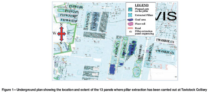
The available coal reserves have dwindled over time, and the majority of the coal is now locked up in the remaining safety pillars. The pillar extraction project was initiated by this reality and the necessity to extend the life of mine in line with the entire Southstock complex which comprises, the South Witbank, No. 5 Seam, and Tavistock Collieries. To date around 655 000 t of coal has been safely extracted from the pillar extraction panels, as indicated on the Tavistock Colliery underground plan in Figure 1. The in-house process developed and implemented towards achieving this in a safe and efficient manner will be discussed.
Mining methods at Tavistock Colliery
Historically, the mining of the available coal reserves was never carried out with the intention to conduct pillar extraction on retreat, and hence the original pillar design was usually based on the maximum percentage extraction to be achieved during the primary development mining phase6. Bord and pillar mining has been the prime method employed for coal extraction since production commenced at Tavistock Colliery. At first, mining was carried out entirely by conventional methods (drill and blast) until the introduction of mechanized mining using a continuous miner (CM) during 2004.
Pillar extraction experience at XCSA
Pillar extraction was initially carried out making use of a total pillar extraction mining method at the Arthur Taylor Colliery (ATC), with goafing occurring concurrent with the mining. Although no fatal accidents were recorded, there were at least two recorded cases of a CM burial and one major windblast accident during this period. This was formally addressed through the re-design of the pillar extraction method to mitigate any CM burials and windblast accidents. The group rock engineer at the time, Mr B. Vorster, employed a Modified NEVID method based on the pillar extraction mining method developed by Sasol Mining.10 This method of pillar extraction was then carried out at Spitzkop Colliery, ATC, and also later at Boschmans Colliery, with no recorded cases of a CM burial or any windblast accidents.
It must, however, also be pointed out that the method was not effectively designed for goafing to occur concurrent with the mining operation. There are at least three recorded cases of surface subsidences having occurred at Boschmans Colliery after the pillar extraction operations had formally ceased. There is no recorded case of any surface subsidence at Spitzkop Colliery where pillar extraction operations were carried out.
Pillar extraction at ATC was carried out on only the No. 4 Seam with no pillar extraction carried out on the No. 2 Seam. Interestingly enough, pillar extraction was also carried out on the No. 4 Seam in areas where the No. 2 Seam had previously been mined out below, in addition to those areas where the No. 2 Seam was not mined out previously. The modified NEVID method employed at ATC and Boschmans consisted of taking only three cuts per pillar where possible, which will be discussed later.
Mining process adopted for the safe and effective pillar extraction at Tavistock Colliery
A formal process for evaluating the viability of pillar extraction mining, including all of the key stakeholders, was initiated towards gaining a better understanding of the process. In this regard a number of workshops, sessions, and also mine visits were carried out, in which the following factors were identified for consideration. For simplicity, these factors can be effectively grouped into the Mining and Geotechnical aspects, which will be discussed in the following sections:
Mining considerations
These were addressed by identifying the key activities and allocating resources and personnel to ensure that these were effectively managed.
Mining restrictions (pillar extraction panels available)
Surface and underground
The first challenge confronting Tavistock Colliery was the availability of panels originally earmarked for pillar extraction, owing to the restrictions imposed by various surface structures including public and private roads, buildings, and dams (Figure 2).
Based on the analysis carried out, approximately 30% of the original panels earmarked for pillar extraction had to be scrapped due to further expansion plans for water storage facilities on surface, which were to be extended and in the process would encroach into the mineable and targeted pillar extraction areas. In addition to this, there were also the adverse effects associated with combined floor rolls, paleohighs, hydraulic pressure conditions, and panel orientations, resulting in further panels having to be removed from the pillar extraction schedule.
External and internal stakeholders
Farmers likely to be affected during this process were consulted well in advance. Fences were erected around the planned pillar extraction panels in order to prevent inadvertent access to the surface areas where subsidence could occur. Prior to the commencement of the pillar extraction mining there was already a project underway to relocate affected communities in informal settlements. The trade unions representing the workforce were also duly informed about the pending pillar extraction operations and involved throughout the process. No major complaints were received from any of the abovementioned stakeholders during the pillar extraction operations.
Mine planning
A detailed mine design utilizing the available coal resources and pillar extraction panels indicated that the Tavistock underground operation will be able to continue until December 2011. The development is expected to continue with two sections and the pillar extraction with the other two sections until the end of the year. At the time of publication Tavistock Colliery has just been closed with the last mining taking place on the day shift of the 30th of January 2012.
Cost and production
Based on the comprehensive mining exercise carried out on the available pillar extraction panels, the pillar extraction method was deemed a viable option due to its positive NPV contribution and minimal capital input required. The ROM production was originally forecast at 55 000 t/month for a three month period with the intention to ramp up to 80 000 t/month. Production commenced in March 2010, and was stopped for two weeks due to a fall of ground that necessitated the panel to be relocated following an extensive analysis on the failure mechanism carried out by various rock engineering experts, as discussed later. It was in November 2010 that Tavistock finally achieved 86 000 t/month from the pillar extraction section for the first time.
Availability of equipment
A strategic decision was taken to gradually phase out all single-pass continuous miners in preparation for mining remnants and pillar extraction. Two ABM30 and one ABM12 continuous miners were decommissioned and replaced with three HM31 continuous miners. Provision was also made in the budget to replace the existing RHAM single boom with RHAM twin-boom roof bolters in order to match the roof support requirements. A machine extractor 'tande-trekker' was also purchased to be on standby in the event that the CM becomes stuck or buried by the goaf.
The scrubber fan on the CM was initially removed as part of modifications carried out, but at a later stage it was realized that it was not necessary provided that the fan could be switched off. The scrubber fan is required for use in all planned holings or developing prior to the pillar extraction that is carried out on retreat.
Support and rehabilitation of the pillar extraction panels
It was decided to outsource the re-support of those panels identified for pillar extraction services to a secondary support contractor using hand-held machines, due to the versatility of the equipment and easy access to these old workings. A detailed pillar extraction panel support assessment was also carried out15, documented, and signed off by the rock engineering department together with the mining department and project-managed through an independent company towards ensuring that this aspect did not become an issue on the project critical path. In order to keep up with frequent panel relocations, there would need to be at least two pillar extraction panels prepared in advance at all times. Preparation in this regards also involved the pumping of any water, rehabilitating the ventilation infrastructure, sweeping/cleaning, construction of travelling ways and conveyor belts, as well as the power and water supply to the working place. All belt roads and travelling ways would be supported from the beginning of the panel right up to the faces, and this also included the installation of systematic roofbolt breaker lines5. Breaker line support (Figure 3) consisted of two rows of 1.8 m long x 20 mm diameter full column resin-grouted roofbolts installed 1 m apart with five bolts installed per support row, across the width of a bord specifically to:
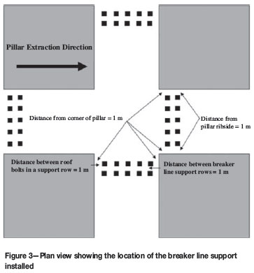
Arrest the planned displacement of the roof strata at that point
This system has been proven to be very successful in past pillar extraction projects at XCSA. Mining in a panel could commence and continue after four rows of splits from the face had been re-supported to the required standard.
Labour issues and challenges
Some challenges with regard to the compensation for machine operators demanded by the labour unions were overcome through a process of constant engagement. It is understandable that pillar extraction involves hazards that are different to those of development, but these are effectively managed and mitigated through the risk assessment process adopted.
Availability of competent skills and training
Following the closure of the ATC and Phoenix underground operations, key employees were identified and transferred to other operations, and during this process a number were also transferred to Tavistock Colliery. All mining personnel such as shift bosses and miners and CM operators who had prior working knowledge of pillar extraction from ATC were identified and included in the labour planning. A formal training programme was also initiated and carried out by the rock engineering department with the mining crews towards ensuring that the relevant strata control issues and training on the critical controls were provided to the mining personnel, on issues such at the trigger action response plan (TARP), daily inspection checklist, and the marking and cutting of the pillars.
Risk management process (risk assessment)
An issue-based risk assessment16 for producing coal in a pillar extraction section was developed on the mine with the objective of assessing the availability, adequacy, and effectiveness of the hard barriers (these are physical barriers, such as lockouts and no-entry barricades, as opposed to soft barriers such as procedures and discussions), and to identify required procedures and standards in order to address the high risk/critical tasks. During this process the following key issues were identified, and a schedule with accountabilities established and tracked:
Panel pre-emptive document
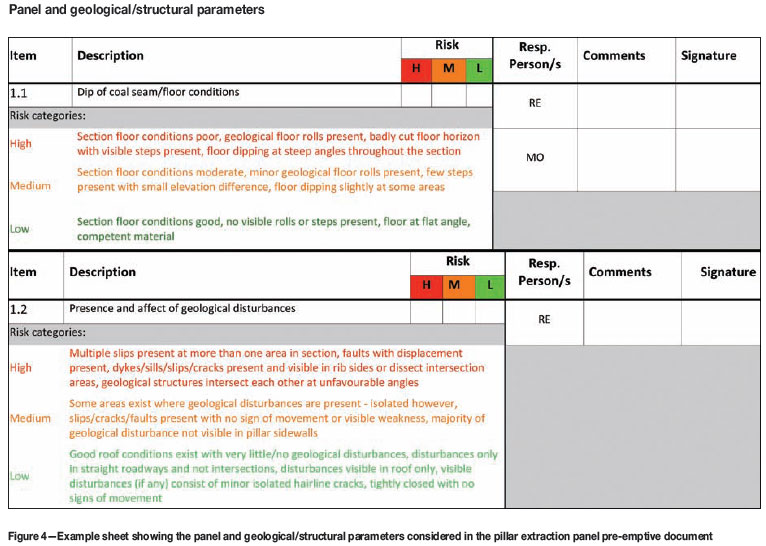
Prior to pillar extraction taking place in a specified panel, the various affected stakeholders (departments) come together in a formal manner to identity all the possible hazards and the likely related risks anticipated during the pillar extraction process, and through this consultative process define the controls required in order to reduce the risks to the underground personnel (Figure 4). The process is carried out by critically considering and assessing the following key issues:
At the conclusion of the meeting the completed pillar extraction panel pre-emptive document is duly signed off by all parties and a permit to mine signed and issued by the operations manager.
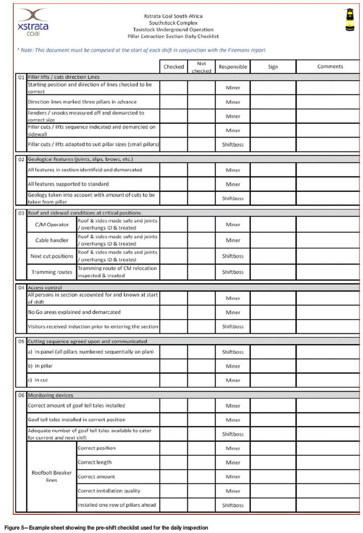
Daily inspections
In order to ensure full compliance to the standards set for safe pillar extraction, inspections are carried out on a daily basis by the miners and shift bosses as well as the mine overseer. These are carried out by means of a pre-shift checklist that encompasses, amongst others, the following key aspects (Figure 5):
Trigger action response plan (TARP)
A TARP was also developed for the pillar extraction towards managing the various critical aspects that would affect the extraction operations and was included as part of the training process provided to the mining personnel, (Figure 6).
Recovery of an inoperable continuous miner in a pillar extraction section
A procedure was developed with the main objective to ensure that the continuous miner could be extracted and/or recovered from a position where it has become inoperable. This position can be expected to occur beyond the roofbolt breaker line support, and in essence means that the machine has become inoperable in a deemed no-go zone.18
Pillar cutting sequence in a pillar extraction section
A procedure was developed with the main objective to ensure that a standard cutting sequence is adhered to in a pillar extraction section that will define the sequence in which each identified pillar in a row must be cut, the amount and sequence in which individual lifts/cuts from a single pillar must be taken, and importantly indicate the position that the CM operator and his assistant must take in order to ensure that they do not enter into a 'no-go' zone while cutting17 (Figure 7).
Geotechnical considerations
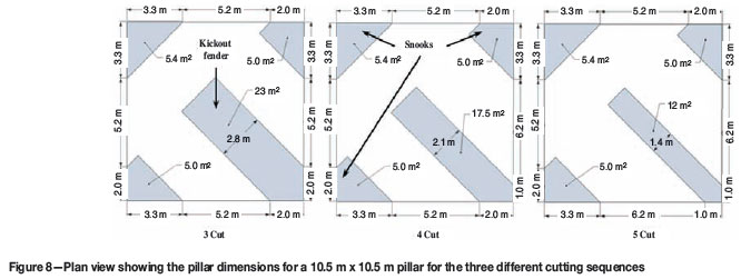
The pillar extraction operation at Boschmans Colliery was carried out by means of taking only three cuts per pillar (Figure 8) where practicable, and mining four to seven rows of pillars in this manner, after which two rows of intact pillars were left as stopper pillars. The intention of the stopper pillars was to mitigate the effects of a windblast. Although this method was found to be a much safer way to carry out pillar extraction, with a very low risk of CM burial and windblast accidents as compared with the earlier total pillar extraction carried out,11,12 there was no recorded goaf that occurred concurrent with the pillar extraction mining.
Due to the risks inherent in the non-goafed panels, a meeting was arranged with all stakeholders and experts towards reviewing, and where possible amending, the pillar extraction cutting sequence employed at Boschmans Colliery for implementation at Tavistock Colliery.
The various geotechnical aspects considered are discussed below.
Geotechnical borehole logs
Due to the poor quality of the information available on some of the older geological borehole logs and the lack of adequate geological coverage in the pillar extraction area of interest, it was decided that initially at least two new geotechnical boreholes would be drilled per pillar extraction panel and logged. The geotechnical boreholes would be drilled from surface to a position just above the immediate roof and located in the centre of the pillar extraction panel. The main purposes of these boreholes were firstly to enable the calculation of the minimum spans for the various panels to be carried out, and also to ascertain the general roof composition of the panel in question. A subsequent use identified for these boreholes was for instrumentation, which will be discussed later. A plan, together with a drilling schedule covering all of the pillar extraction panels, was discussed and drawn up in consultation with the Complex geologist, and this was then also effectively project-managed towards ensuring that the required information was always available prior to the pillar extraction taking place in the panel.
Using the available geotechnical information, the minimum spans required for overburden failure to occur were calculated for each panel considering only the strongest sandstone layer and assuming a tensile mode of failure, using the following equation1:
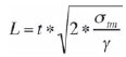
where, σtm is the sum of the tensile strength of the beam and the resident horizontal stress, γ is the distributed load on the beam, assuming a unit weight of the overburden strata of 25 kN/m3, t is the thickness of the beam, and L is the minimum span. The results of this analysis are shown in Table I.
Numerical modelling - LAMODEL4
For the modelling exercise the LAMODEL numerical modelling software package was used, which is a boundary element program for calculating the stresses and displacements in coal mines or other thin, tabular seams or veins. It can be used fairly easily to investigate and optimize the required pillar sizes and layouts in relation to pillar and multi-seam stresses. LAMODEL simulates the overburden as a stack of homogeneous isotropic layers with frictionless interfaces, and with each layer having the identical elastic modulus, Poisson's ratio, and thickness. LAMODEL was used towards establishing and quantifying the extraction safety factors [ESF] for a representative range of panel spans and depths, together with the number of pillar cuts. The decision was taken to modify the existing NEVID mining method for the prevailing ground conditions in order to increase the likelihood of goafing in the pillar extraction panels as follows, without increasing the overall risk profile, refer to van der Merwe1:
All geological discontinuities identified during the pillar mapping exercise were incorporated into the designing and positioning of the required cushion pillars as far as practicably possible. Once the goaf in a panel has been initiated and progresses with the subsequent mining, the cushion pillar requirement falls away and the pillar can be mined depending on the outcome of the pillar mapping exercise.
During this exercise a simple and effective process flow was developed for the pillar extraction operation mining at Tavistock Colliery8 (Figure 9).
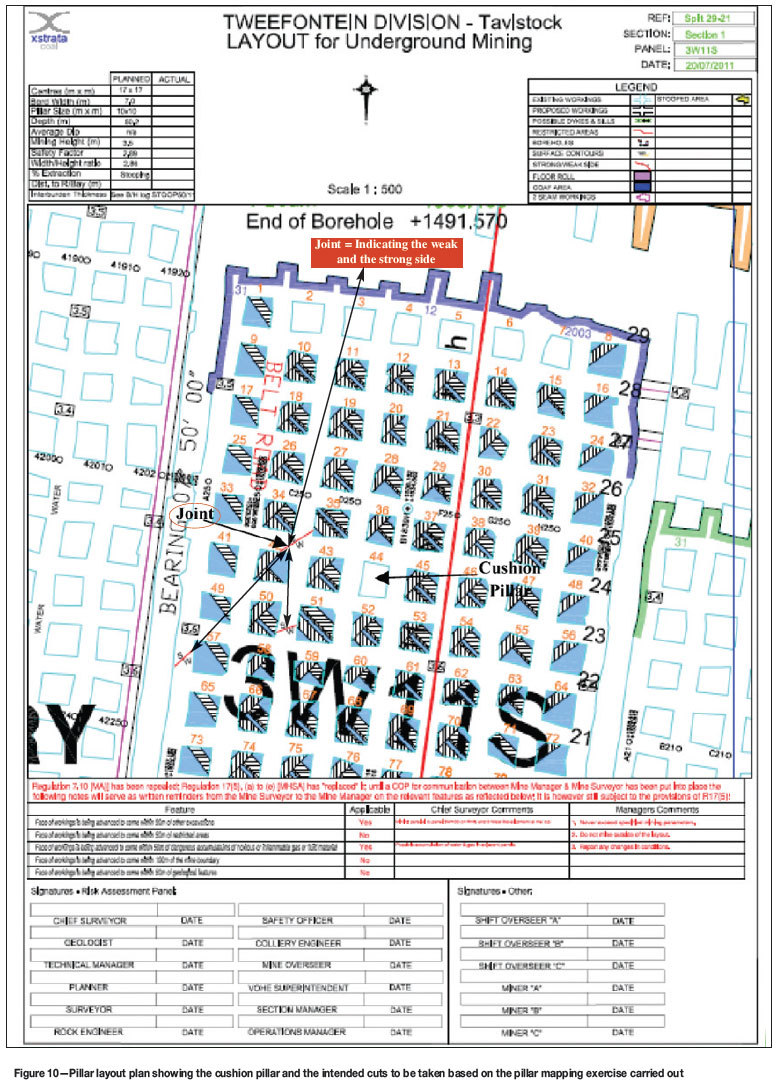
Panel mapping exercise
This entails an assessment of the various geotechnical parameters that can directly affect the behaviour of the pillars and immediate rock mass during the pillar extraction process. During this process, all the underground panels that were planned for pillar extraction were visited, and the following parameters were assessed and the information captured on the survey plans to ensure that the pillar extraction of each panel is carried out in a safe and efficient manner:
Once the information had been captured, a detailed pillar and risk assessment layout plan was generated which forms part of the pillar extraction pre-emptive risk assessment process. A signed-off copy of the pillar layout plan was then provided to the miners (Figure 10).
Instrumentation
It was decided to carry out a simple instrumentation programme in order to gain a better understanding of the overburden behaviour during the pillar extraction process. In this regards a decision was made to implement the time domain reflectometry (TDR) technology, which is a fairly simple and cost-effective geotechnical monitoring system that is generally used in massive mines to determine the height and profile of the cave above the draw point. TDR works through propagating a radar frequency electromagnetic pulse down a transmission line while monitoring the reflected signal. As the electromagnetic pulse propagates along the transmission line, it is subject to impedance by the dielectric properties of the media along the transmission line. For a customized mining application solution, the system consists of grouting a specific type of conductive cable with known electrical properties into a surface borehole. A total of five of the geotechnical boreholes were instrumented with the TDR cabling (Table I), consisting of three cables of different thickness in each borehole, with the intention of understanding the overburden behaviour during the pillar extraction. A limited degree of success was achieved with the TDR instrumentation; however, this technique does not lend itself to providing early warning (precursor) information of overburden instability and should rather be used to provide information related to the location, rate, and extent of roof failure that occurs during and after pillar extraction.
GoafWarn
Previous work carried out by Brink et al.2, and Edwards3 indicated the need for a reliable early warning seismic system indicating major roof instability in a coal mine, considering the significant percentage of reserves tied up in coal pillars. Following this the GoafWarn instrument was developed, which is installed approximately 50 m to 100 m from the region where any such roof instability may occur. The device monitors the micro-seismicity associated with the formation and extension of fractures which are the precursors to the larger instability process that follows. The instrument comprises a seismic velocity sensor, analogue-to-digital conversion, and a microprocessor for data processing.
Two of the older generation GoafWarn instruments were obtained to trial from CSIR Miningtek, with the purpose of using them in the pillar extraction section to build up an understanding of how the roof behaves prior to, during, and after the goaf. Unfortunately, no success was achieved with these instruments because of issues with the software and timing, and thus valuable information regarding the actual goafs recorded was lost in the process.
Going forwards, new-generation GoafWarn instruments will be purchased to allow for remote reading and accessing of the data, thereby providing a real-time solution to the challenge at hand of understanding the roof behaviour.
Pillar extraction section performance rating form
As part of the compliance process, a pillar extraction rating form was designed to rate the section performance of the underground mining personnel against the set standards and procedures. The form addresses and assesses, amongst others, the following key factors:
The performance rating form is compiled during the startup phase of the new pillar extraction panel and during the month, with the results discussed and communicated to the mine overseer.
Implementation phase
Pillar extraction success
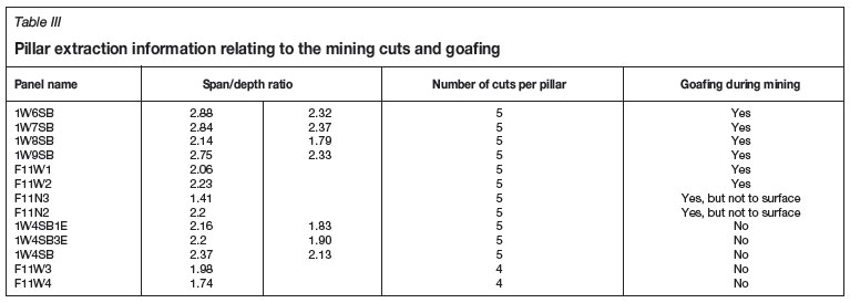
The pillar extraction operation at Tavistock Colliery started during April 2010 with the panels situated on the eastern side of the mine, viz. 1W4SB1E and 1W4SB3E (Figure 1). To date the pillar extraction has been effectively carried out on a total of thirteen panels, and there has been goafing in eight of the panels (Table II). A summary of the goafing information for the pillar extraction panels as well as their orientation is provided in Table III.
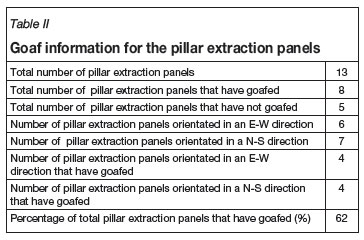
As stipulated in Table II, only 62% of the pillar extraction panels have goafed while the mining was being carried out. It is pertinent to note that the pillar extraction in three of the non-goafed panels was undertaken by using five cuts on each pillar, whereas the remaining two were extracted using four cuts per pillar. In all of the panels where goafing occurred during mining, the pillar extraction was undertaken by using five cuts on each pillar where practicably possible. It is important to take note of the central remnant portion of a pillar left during pillar extraction (kickout fender) that is created with the three different mining options used on XCSA. In this regard the area of the kickout fender increases from 12 m2 (1.4 m thick) to 17.5 m2 (2.1 m thick) and to 23 m2 (2.8 m thick) for a 5 cuts, 4, to 3 cuts per pillar respectively, (Figure 8). From the pillar extraction information gathered to date at XCSA, the relationship of the size and performance of the kickout fender and the roof behaviour is a crucial aspect that needs to be studied in more detail towards garnering a better understanding of the roof failure mechanism for pillar extraction of small pillars at shallow depths. In this regard, the UDEC and FLAC3D numerical modelling packages will be able to provide further clarity and insight.
Challenges experienced and further enhancements
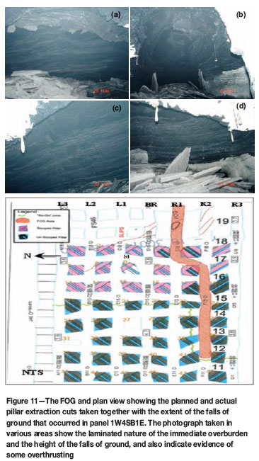
Goaf overrun and fall of ground
There has been one recorded incident of a fall of ground (FOG) and a goaf overrun since the inception of pillar extraction operations at Tavistock Colliery. The FOG occurred in panel 1W4SB1E where the pillar extraction operation commenced (Figure 1). The FOG occurred on the off-shift during cutting of the third row of pillars, and was noticed along the roadway R3 from split 14 to split 19 (Figure 11). The fall progressed up to split 12 located adjacent to the waiting place. All the operations were ceased in this panel for the safety of the underground personnel. An extensive investigation was conducted by the rock engineering department towards understanding the mechanism of this FOG, and Mr Jaco van Vuuren of Saxum Mining, Professor Nielen van der Merwe, and Mr David Postma the group rock engineer at Sasol Mining were also consulted. The FOG was attributed to the combination of the floor roll, water in the roof, and the stress changes associated with the east-west orientation of the pillar extraction panel.9,13,14
Following this incident it was decided that in addition all floor rolls will be mapped and captured on the survey plan to ensure that this is taken into consideration during the design of the pillar cutting sequence. In addition, deeper bleeder holes (3.9 m in length) will be drilled at the roadway R3, roadway L3, and the belt road for every third split for the draining of any water from the immediate roof, in order to prevent the build up of any hydraulic pressure, which tends to cause strata problems. Intensive monitoring of the ground conditions will also be carried out while mining the panels in the east-west or west-east direction.
Pillar cracking
The mining of panel F11W1 was successfully carried out with a goaf occurring as planned, though not up to surface, and with no abnormal pillar and roof conditions observed prior to the commencement of the pillar extraction operation. It was, however, noted during the process of extracting pillars in this panel that the southern barrier pillar started to develop guttering on the right hand side of panel F11W2 (northern side). After completion of the pillar extraction in panel F11W1, preparations were made to commence with the pillar extraction in panel F11W2. The first goaf happened after nine rows of pillars had been extracted, and this also did not progress up to the surface (Figure 12). After mining a further two rows of pillars the next goaf occurred, which triggered all of the uncompleted goafs (the goaf in panel F11W1 and the first goaf in panel F11W2) to progress. The goafing then proceeded to alternate between the two panels for about an hour. Following this it was noted that the pillars extending from the goaf line backwards had developed an interesting tensile crack extending from the top to the bottom of the pillar corner (Figure 12). This was observed in panel F11W2 and also F11W3, the next panel planned for pillar extraction. These tensile cracks were observed on both the eastern and western sides of the pillars, with minor guttering noted on the southern side of the pillars.
It was concluded that the damage to the pillars observed was as a result of lateral displacement, due to the sudden release of horizontal compression accompanying the progression of the goaf in the adjacent panel. The layout plan was altered to leave four rows of pillars to stiffen up the system, and pillar extraction resumed. A special modified cutting sequence was developed for panel F11W3, taking cognisance of the cracks and guttering. In this sequence the planned cuts on the sides of the pillars where the cracks had developed were removed, in order to prevent the already fractured dislodged corners from falling and thereby causing injuries to personnel or damage to the equipment.
In conclusion, pillar extraction of the panels orientated in the east-west or west-east direction, probably coinciding with the direction of maximum horizontal stress, can present challenges that need to be managed.
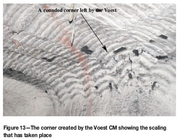
Scaling of pillar corners in areas where the previous mining was carried out using a Voest CM
Scaling occurred during the extraction of pillars that were originally mined using a Voest CM, which tends to create a rounded pillar corner in the roof (Figure 13). This corner tends to scale off with the stress changes associated with the pillar extraction operation. Two incidences were also reported of the Hilti gun causing this fractured piece of rock to become dislodged, resulting in an injury to an employee during the normal installation of brattices required for ventilation control.
Conclusion
The pillar extraction process designed and carried out at Tavistock Colliery has proved to be a success in terms of safety and efficiency, and has enabled a better understanding to be gained of the behaviour of small pillars at shallow depths during pillar extraction. The work has shown that it is possible to extract old, small, shallow pillars that were not originally intended for secondary extraction, provided that detailed prior investigation is done and that the mining is planned in great detail and executed according to plan.
Based on the experience to date, there is still, however, further numerical modelling work that needs to be carried out towards understanding the behaviour and interaction of the kickout fender and the immediate roof response during pillar extraction operations for various panel geometries, stress orientations, and depths towards formulating guidelines.
It is also necessary to improve the understanding of failure mechanisms preceding goafing, which will hopefully be achieved with the implementation of the improved GoafWarn instrument.
Acknowledgements
The authors would like to thank XCSA management for permission to publish this paper, and also acknowledge Mr B. Vorster for all of the earlier pillar extraction work carried out at Boschmans, ATC, and Spitzkop Collieries.
References
1. VAN DER MERWE, J.N. Rock engineering method to pre-evaluate old, small coal pillars for secondary mining. Journal of the Southern African Institute of Mining and Metallurgy, vol. 112, no. 1, 2012. pp. 1-6. [ Links ]
2. BRINK, AVZ. and NEWLAND, A.R. Automatic Real Time Assessment of Windblast Risk. ACARP project C8026, Australian Coal Associatio n Research Program, 2001. [ Links ]
3. EDWARDS, J. Seismic monitoring for windblast prediction. Mine seismicity and rockburst risk management in underground mines. Australian Centre for Geomechanics, 1998. pp. 14-1 to 14-6. [ Links ]
4. HEASLEY, K.A. and AGIOUTANTIS, Z. LAMODEL-A Boundary Element Program for Coal Mine Design. Proceedings, 10th International Conference on Computer Methods and Advances in Geomechanics, Tucson, Arizona, 2001, pp. 1679-1682. [ Links ]
5. VAN DER MERWE, J.N. and MADDEN, B.J. Rock Engineering of Underground Coal Mining 2nd edn. Johannesburg, Safety in Mines Research Advisory Committee, 2010. [ Links ]
6. HSEC COP 013-XCSA Guideline for COP-Combat Rockfall accidents in Underground Mines, 2011. [ Links ]
7. Pillar Extraction Code of Practice. Tavistock Colliery, 2010. [ Links ]
8. VAN DER MERWE, J.N. Xstrata Coal Personal communication. Centennial Chair for Rock Engineering, School of Mining Engineering, Wits, 2011. [ Links ]
9. POSTMA, D. Personal communication. Group Rock Engineer, SASOL, May 2010. [ Links ]
10. VORSTER, B. Personal communication. Principal Geotechnical Engineer, Xstrata Coal, Queensland, 2009. [ Links ]
11. STRATA ENGINEERING. Evaluation of the Stability of Pillars in Existing Secondary Extraction Panels. report number 08-001(XST)-1, June 2008. [ Links ]
12. STABLE STRATA CONSULTING. Stability Analysis of Xstrata Pillar extraction. Proposal, October 2007. [ Links ]
13. SAXUM MINING. XSC 1004-281 Tavistock Section 2 FOG April 10. 1st draft, April 2010. [ Links ]
14. TAVISTOCK COLLIERY. Fall of ground that occurred at the Tavistock pillar extraction section panel 1W4SB1E, Internal report, April 2010. [ Links ]
15. TAVISTOCK COLLIERY. Support requirements for the planned Tavistock Colliery pillar extraction panels. Internal report, April 201. [ Links ]
16. TAVISTOCK COLLIERY. April 201,Issue Based Risk Assessment-Producing coal in a pillar extraction section. Internal report, March 2010. [ Links ]
17. Tavistock Colliery. SSCC UM S001-Pillar cutting sequence in a pillar extraction section. Internal report, April 2010. [ Links ]
18. Tavistock Colliery. ESP 47 Recovering of an inoperable Continuous Miner in a pillar extraction section. Internal report, March 2010. [ Links ]
This paper was first presented at the, MineSafe Conference, 15-18 August 2011, Emperors Palace, Hotel Casino Convention Resort, Johannesburg.
© The Southern African Institute of Mining and Metallurgy, 2012. SA ISSN 0038-223X/3.00 + 0.00.

