


Servicios Personalizados
Articulo
 Inglés (pdf)
 Articulo en XML
 Referencias del artículo
Indicadores

Links relacionados
-
 Citado por Google
 -
 Similares en Google
Compartir

 Permalink
SAIEE Africa Research Journal
versión On-line ISSN 1991-1696
versión impresa ISSN 0038-2221
SAIEE ARJ vol.115 no.1 Observatory, Johannesburg mar. 2024
Evaluation of unconventional partial discharge and Tan Delta assessment techniques on medium voltage cable terminations with artificial defects
J.V. Bissett; P.A. van Vuuren; J.J. Walker
IErongo Regional Electricity Distributor, Walvis Bay, Namibia. He is registered as a Professional Engineer with the Engineering Council of Namibia. (e-mail: vbissett@erongored.com.na)
IIFaculty of Engineering of the North-West University, Potchefstroom, South Africa (e-mail: pieter.vanvuuren@nwu.ac.za)
IIIFellow, SAIEE. Walmet Technologies, South Africa. He is a Fellow of the South African Institute of Electrical Engineers (email: jerrywalker@walmet.co.za)
ABSTRACT
Reliable cable systems are of utmost importance for electricity distribution- and grid networks. Cable terminations are key components of cable systems but also contribute significantly towards unwanted cable failures and power outages. Although well-developed standards exist in the electricity industry, it is not always possible to execute the most effective tests at power frequency due to financial or logistical reasons. Hence, withstand voltage- and Partial Discharge tests at power frequency are only conducted at a low percentage of electricity utilities. This paper presents the evaluation of unconventional partial discharge fault detection techniques and Very Low Frequency Tan Delta measurements on different cable termination defects. Five artificial cable termination defects were created on single core 6.35/11kV cross linked polyethylene cables, with one "defect-free" termination and five defective ones. Power frequency voltage was applied at increased voltage steps to initiate aging acceleration due to partial discharge. This resulted in insulation deterioration and eventual termination failure. Different data sets were obtained from the Very Low Frequency Tan Delta measurements as well as for the unconventional Partial Discharge measurements. The sequence of failures is compared between the two data sets and evaluated against the root cause failures of the terminations as evaluated by an industry expert. High Frequency Current Transformer and capacitive coupling sensors were used together with an advanced partial discharge data acquisition system. Partial discharge analysis was done to relate the specific on-line trending data with termination failure. Good correlation was found between the two data sets which supports the utilization of unconventional partial discharge measurement for cable acceptance testing.
It would be beneficial for the electricity industry to consider unconventional Partial Discharge technology as a suitable alternative for on-site acceptance tests for cable terminations.
Index Terms: Partial Discharge (PD), Remaining Useful Life (RUL), Tan Delta (TD), Termination, Unconventional Partial Discharge, Very Low Frequency (VLF)
I. INTRODUCTION
In the Electricity Distribution Networks, cable terminations as part of cable systems are of utmost importance for the effective management of distribution networks to ensure reliable electrical networks. Although underground cable distribution networks are more reliable compared to overhead power-line counterpart, underground cable systems require more advanced engineering methods to locate and repair cable faults. Electricity utilities make significant investments to maintain the necessary skill sets and test equipment to maintain and repair cable systems in an efficient and effective manner. Paper Insulated Lead Cables (PILC) are less vulnerable to poor workmanship compared to Cross Linked Polyethylene (XLPE) cables. Ensuring good quality management when cable splicing and termination are performed by artisans remain a challenge for many electricity utilities in the South African Development Community (SADC).
Although adequate industry standards are available, both internationally and locally, it appears that on-site commissioning and acceptance tests remain a challenge for most utilities. This is evident if one considers the high percentage of splice and termination failures. Although various tests are performed on site, there is sufficient evidence from utilities [1] [2] that cable termination failures remain high and are not achieving the designed life expectancy of 30 to 40 years. Cable systems are being tested in accordance with many different industry standards during acceptance and maintenance field testing of medium voltage under-ground cable systems. The question arises how effective is cable termination testing really to ensure good workmanship with high confidence levels. Termination and cable testing at factory premises differ significantly from on-site testing during commissioning. It should also be noted that the environment in which the tests are conducted differ in many ways.
It is industry practice that cable systems (cable with splices and terminations) are being tested as a complete system, meaning that there is no differentiation between the cable itself and the terminations and joints. As a minimum requirement, VLF voltage withstand [3] test is popular as an acceptance test before energizing the cable system but does not provide any level of acceptance and is purely used as a pass or fail test. Partial Discharge (PD) testing [4] has become more popular in the recent years and is one of the most reliable test methods for condition assessment of cable systems. During the execution of the experiment, PD assessment at power frequency was initially used to assess the six cable samples. Thereafter, during the weekly periodic assessments, VLF PD was also conducted on the cable samples.
An experimental set-up was prepared with six single core XLPE cable termination samples as test objects. Artificial termination defects were introduced on five samples, with one sample having no defects and made to the highest possible workmanship standards. The aging deterioration process was performed by increased power frequency overvoltage for certain durations. During the four-week evaluation period, both electrical tests as well as unconventional PD monitoring were conducted. The monitoring equipment was set-up and configured to provide for continuous trending through a data acquisition system connected to two types of sensors for each cable system resulting in a total of twelve channels. The trending data with various parameters are analyzed to evaluate and compare the data with the sequence of termination failures.
Tan Delta (TD) measurement as a reliable test method for cable condition assessment is comprehensively prescribed [4] in many of the standards, especially for service aged cables but also for newly installed cable systems. Hence, VLF TD was extensively used during the weekly periodic cable sample assessment, and mean TD as well as derived Delta Tan Delta (DTD) values are used for overall performance assessment of cable samples.
Although limited research to date was done by applying the unconventional measurement method on cable terminations, significant potential was demonstrated to indicate the strong correlation between conventional- [5] and unconventional [6] methods. HFCT PD measurements were successfully used to distinguish between eight different termination defects [7]. The only disadvantage observed was the limited sensitivity for inception voltage with the sensor used during the experiment. Additional experimental studies on artificial defects on terminations confirmed that it is possible to recognise three common defects (feather, tramline and ring cut) by making use of conventional partial discharge measurements [8]. There is great similarity between conventional and unconventional partial discharge technology, which further supports the use of unconventional methods for cable termination assessments.
The standard for unconventional PD measurements [6] prescribes the measurement of partial discharges by electromagnetic and acoustic methods. Successful computer simulation of created defects within cable terminations revealed excellent relationship between defect type and size in relation to the acoustic frequency [9]. The conventional method was successfully used to identify workmanship compromises on common and typical termination defects, namely semiconductor feather, tramline and ring cut, in the XLPE insulation [8].
This paper presents the results obtained from the conducted experiment and focuses on the Tan Delta and unconventional PD monitoring datasets. Analysis combined with comparison between the datasets and the actual termination failure sequence are critically evaluated. Termination failure root cause analysis with industry expert is included and compared with the datasets. Good sensitivity of the PD monitoring system has the capability to identify poor workmanship at an early stage. The unconventional PD measurement method could be used as an acceptance test during cable termination commissioning to guarantee the maximum life expectancy, believed to be more than 40 years.
II. Current Testing Methods And Standard For Cables And Terminations
There are mainly three standards or guidelines that should be considered for testing of cable systems in the SADC region: namely the South African National Standard (SANS) [10] [11], International Electrotechnical Standard (IEC60502-1) [12] and the Institute of Electrical and Electronics Engineers (IEEE) [3]. There are great correlation and similarity between the standards, as expected, and many improvements and amendments have been made during the last decade as understanding and technology have evolved over the years. There are, however, also significant differences between the various standards considering the acceptable levels. Especially for cable system commissioning tests, there is a need for a common approach and agreement for standardized commissioning tests [13].
Over the last few decades since 1970, cable system testing methods and standards have improved to accommodate more reliable testing of XLPE cables. Commonly available test methods in the electricity industry applicable to cable systems can be listed as follows [1][2]:
1) DC Test
2) VLF 0.1Hz Withstand Test
3) VLF 0.1Hz Tan Delta Test
4) Offline 50/60Hz PD Test
5) Offline 0.1 Hz VLF PD Test
6) Online Partial Discharge Test
Field testing standards and guides have been written to include these tests, but most are not comparable with factory tests and provide limited certainty of future cable system performance [14] [15].
Power frequency testing at 50Hz is not always possible to execute on site due to unavailability of test equipment in the industry, high cost and significant size of high voltage transformer. Very Low Frequency (VLF) ac testing has therefore been accepted as a preferred test method [16] [17]. IEEE400 [3] is a guide that lists various field test methods that are currently available. This standard describes the tests and gives advantages and disadvantages, with suggested application and typical results.
The IEEE categorizes cables testing into three areas, namely: (a) installation test after cable installation is complete but before splicing or terminating occurs, (b) acceptance tests after the cable system installation, splicing and terminations are completed, but before the cable system is placed in normal service and (c) maintenance tests made during the operating life of the cable system [3].
Various cable PD test methods have been introduced to the industry that ranges from on-line to off-line [4] [5] [6], as well as making use of different power sources to energize the cable test circuit.
The following specific standards were considered applicable to the experiment, focusing on partial discharge (PD) - and Tan Delta (DT) testing, namely SANS 1339 [11] that gives acceptance level for PD on newly installed cables, and IEEE 400.2 [18] that gives condition assessment figures for VLF TD measurements.
A. Partial Discharge testing
SANS 1339 [11] states when a cable is subjected to a partial discharge test in accordance with the voltage rating of the cable, that the partial discharge magnitude at 1.73 Uo (power frequency) shall not exceed 5 pC. In order to execute this test on site, a power frequency variable voltage source is required. Such sources are not freely available to electricity utilities which make this test impractical to execute on site.
PD testing should be conducted in accordance with IEC 60270 [5] which prescribes high voltage test techniques for partial discharge measurements. This standard prescribes the test circuit set-up and requirement to get measurements from the test object making use of a direct connected circuit, typically through one or more capacitors. This method is also referred to as the conventional test method for PD. The measuring circuit gives apparent charge values which directly equates to PD current pulses within the test object, together with a Phased Resolved Partial Discharge (PRPD) map. The test setup is considered to have a measuring uncertainty of ±10% or ±1pC (picocoulombs). The disadvantage is the cumbersome logistic to set up the expensive equipment on-site that will also require the test object to be taken out of service for the duration of the test.
PD testing can also be conducted with a transportable Very Low Frequency (VLF) source, typically at a frequency of 0.1Hz [18]. Test times and maximum voltages are prescribed according to the standard. PD activity is monitored by raising and lowering the voltage in a very specific sequence. PD initiates and extinguishes at certain voltages, which are recorded as partial discharge inception (PDIV) and extinction voltage (PDEV), respectively. These values provide insight into the condition of the cable and can be used for diagnostic assessments. PRPD maps are also created to provide further insight into the type of fault. Main disadvantages are that external surface discharges may influence the PD test results as well as somewhat difficult interpretation of PRPD maps.
B. Dissipation Factor (Tan Delta) Testing
SANS and IEEE both prescribe Tan Delta testing for serviced age cables as well as new cables.
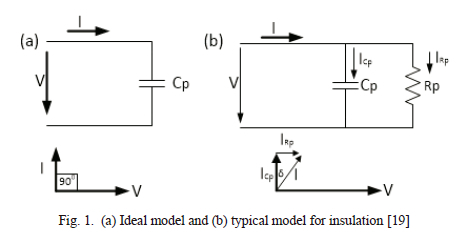
Dissipation factor, also called Tan Delta (Tan 5) or Loss Angle testing, is a diagnostic method for testing cables to determine the quality of the cable insulation [19]. If the insulation of cable is free from defects, like water trees, electrical trees, moisture, voids or any other contaminations, the cable approaches the properties of a perfect capacitor as illustrated in Figure 1(a). In the typical and more realistic model as illustrated in Figure 1(b), resistive current will be evident which will result in an angle of less than 900. The extent to which this angle will shift is indicative of the level of insulation contamination. TD is therefore an excellent indicator for quality and reliability measures [17].
Tan Delta interpretation is based on three individual measurements, namely the mean or average of Tan Delta (TD), the differential value or Delta Tan Delta (DTD) between the measurements at higher and lower test voltages, as well as the standard deviation value or temporal stability (TDTS) value. Condition assessment considers all three values as well as combination of values to make an informed decision.
Condition assessment results are categorized into three groups, namely: no action required (low values), further study advised (moderate values), and action required (for higher values) in accordance with IEEE 400.2 [18]. Various tables are included in this standard for different cables, also differentiating between service-aged cable and new cable. Tan Delta cable testing is therefore an attractive means to group cables in distinctive groups to encourage better management of the asset by giving priority attention to the "action required" group.
Tan Delta was therefore considered a very suitable electrical test with a well-developed standard that can easily be performed for comparison purposes against unconventional PD measurements to assess the condition of cable systems. The interpretation and analysis of TD, DTD and TDTS values contains valuable information about the condition of cable systems.
C. The Benefit And Utilization Of Unconventional Partial Discharge Technology
PD testing has been adopted by industry for both off-line and on-line condition assessment although there are currently limited standards for acceptable levels for various assets like cables, switchgear and transformers. The conventional IEC60270 standard [5] is commonly accepted as one of the best methods to assess the condition of the cable system, although it is seldom performed on site on cable systems at medium voltage range due to unavailability of high voltage test sets and associated high cost.
According to Technical Brochure 662 [20], the benefits of utilising unconventional partial discharge technology could be listed as follows:-
1) Better rejection of electromagnetic interference on site;
2) Distributed measurements and synchronous PRPD pattern evaluation is possible;
3) Suitable for both on-line and off-line measurements;
4) PRPD patterns very similar to those obtained with conventional meaurements.
Unconventional testing equipment is an attractive option for periodic field assessment as well as on-line monitoring for critical installations, mainly because of well-matured technology with attractive cost benefits. Many success stories from electricity utilities reveals huge return on investment after implementation of unconventional partial discharge equipment [21] [22] [23].
III. EXPERIMENTAL SETUP
The specific experimental set-up made use of artificial cable termination defects to obtain measurements and data under certain test conditions due to the lack of real time data containing actual failure rate information. Correlation was sought between the VLF TD electrical measurements and the online continuous PD measurements. Variations and escalation of readings over the duration of the test periods were evaluated in relation to the sequence of termination failures.
A. Preparation Of Artificial Terminations Defects
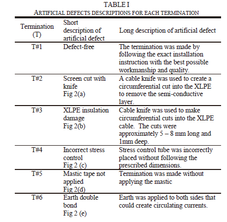
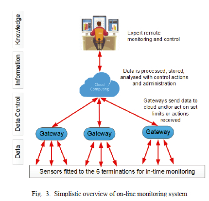
A total of six 6.35/11kV XLPE single core heat shrinkable indoor cable terminations were prepared. These artificial termination defects are summarized in Table I. A competent electrical contractor was identified and appointed to make the cable terminations. The experimental setup was to closely resemble real and actual defects most found in the electrical industry without recording actual dimensions of the defects. The five artificial defects that were investigated in this paper are shown in Figure 2. This was also based on a collective agreement between the electrical contractor, termination manufacturer and experience from both City Power1 and Erongo RED2 as electricity utilities. A summary of the defects is presented in Table I.
B. Unconventional Partial Discharge Measurement Setup
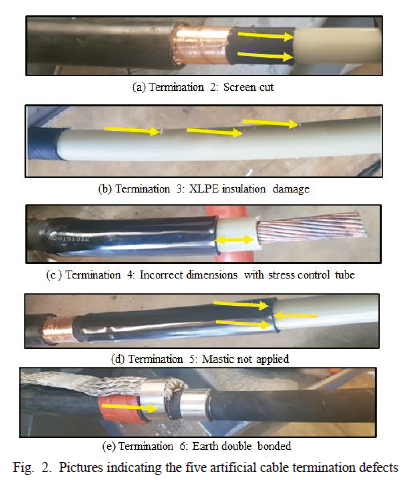
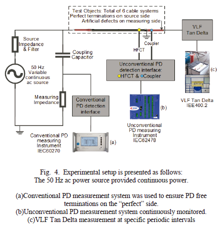
Continuous on-line measurement was required to provide trending information on how partial discharge activity increased up to the point of total insulation breakdown and failure. Martec provided the on-line PD technology by making use of a data acquisition unit, together with communication and web-based dashboard interface. The technology is manufactured by Dynamic Ratings and represented in Figure 3.
Two sensors were utilized. A High Frequency Current Transformer (HFCT) was connected directly onto the earth strap of each cable and a coupler sensor was used on the outer insulation of the cable that was placed in proximity at the termination crutch. The HFCT sensor has a great low frequency response in the 0 - 40MHz range and allows for extended visibility into PD activity occurring at longer distances along the cable. The coupler sensor is a passive, non-galvanic sensor and captures pulses with a wide frequency range up to 300MHz.
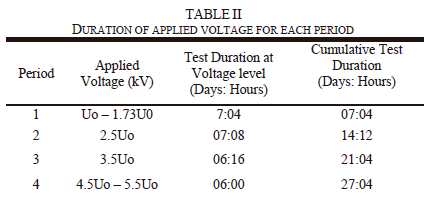
Three measurement quantities were recorded for each sensor, namely Maximum PD (Qmax) in mV, Partial Discharge Intensity (PDI) in mW and Pulses Per Cycle (PPC). The data was recorded for all six cable systems. The measuring period was configured for 30-minute intervals. During periodic intervals, just before the applied voltage was increased to the next step (as per Table II), the VLF PD and Tan Delta electrical tests were conducted at the same periodic interval.
C. Setup of tests and Aging Acceleration Method Applied to the Terminations
The high voltage laboratory at City Power, South Africa, was used to conduct the tests. It should be noted that the laboratory was not certified and accredited to conform to electrical test laboratory standards at the time the experiment was executed but was found suitable for the execution of the experiment. It provided for a controlled environment although not free from interference and noise. This environment therefore resembled typical field conditions.
The electrical setup was done with one single power frequency (50Hz) voltage source that energized all six cable systems together. The good terminations were all connected together at the source end with the remaining ends being available for the PD sensor fitment at the defective termination side. The applied voltage commenced at Uo (6.35kV) and was gradually increased in steps for the duration of the experiment. Figure 4 represents the complete setup arrangement including the three instruments and measurement systems used.
Deterioration of the cable terminations were accomplished by increased applied voltage from 1Uo up to 5.5Uo as presented in Table II. Increased voltage was considered to be a better catalyst for electrical tree growth compared to the more commonly aging parameters. Typical aging test parameters could be summarized as; increase in temperature, increase in moisture after continuous exposure to water, as well as increase in voltage to create higher electrical fields [24] [25] [26]. Successful acceleration of cable termination by applying increased temperature and voltage were demonstrated with corresponding Phase Resolved Partial Discharge (PRPD) recognition [27].
IV. EXECUTION OF EXPERIMENT TO OBTAIN TAN DELTA AND PARTIAL DISCHARGE MEASUREMENTS
The experimental results were obtained from the electrical tests, namely the Very Low Frequency Tan Delta (VLF TD) test and is represented in Figure 5 as DataSet1. The continuous recording of the partial discharge monitoring system is graphically represented in Figure 6 as DataSet2.
A. Off-Line Very Low Frequency Tan Delta Test
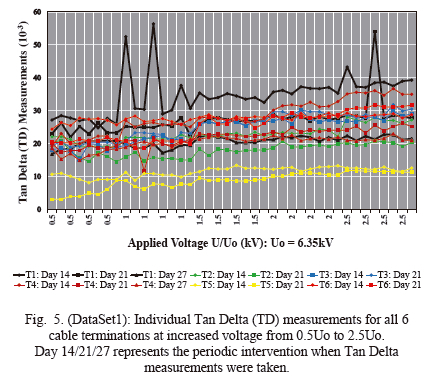
Tan Delta measurements were taken in accordance with IEEE200.2 [18]. Figure 5 represents all the individual measurements (eight measurements at each voltage) taken at 0.1Hz at increased applied voltage (U/Uo) steps with Uo equal to 6.35kV. The maximum applied VLF voltage was increased to only 2.5Uo to ensure that the 50Hz source will deteriorate the cable termination and not the Very Low Frequency voltage.
The following observations and interpretation could be made:
a) Most of the individual TD measurements are below 30 x 10-3, with some above this threshold at higher voltages at 2.5Uo. Values between 4 - 50 according to #t4 (IEEE 400.2) suggest that further study be conducted.
b) Some TD measurements actually improved over the 9-week period, which is surprising and evident on the two cables terminations (T1 and T4) that lasted for the full test duration. The only logical explanation was that the cable lengths were previously exposed to external weather conditions and might have collected water. Oxidation on the copper tape confirmed this.
c) Comparison of the highest and lowest TD measurements (T1 and T5) indicates significant difference. For these two particular cables some noticeable spikes are present in the data set, which could be contributed to voltage breakdowns during that specific time of VLF testing. This emphasizes the importance of taking the mean values of the readings to obtain good average values. Eight measurements were taken at each voltage step as the standard prescribes any number of measurements between 6 to 10.
The values obtained in Figure 5 were then used to calculate the additional indicators required for assessments. Table III represents these indictors for all six cable terminations. The mean of the individual measurements, the differential (A Delta) as well as the standard deviation (Std Dev) values are all derived from the original eight measurement taken at each voltage. Colour coding was applied in the table in accordance with the prescribed values listed in IEEE 400.2 to visually display the results better. DataSet1 is now represented in accordance with IEEE 400.2.
The following observations and interpretation could be made:
a) The mean TD values are all within the medium and high value range. The higher TD values could also be the result of the relatively short length of cable of 7 meters each. The low capacitance will result in higher TD measurements. There is evidence from practical tests on more than 14,000 cables that confirms that tan δ values tend to decrease as the length of cable increases [24].
b) The differential and standard deviation values are derived from the mean values. Hence, it is important to carefully scrutinize the mean values as an important individual indicator. There is a gradual increase in mean values over the 4-week period on all 4 cables that failed, noticeable for Terminations T3, T5, T6 and T2.
c) The differential or delta values are all within the low to medium range with no values recorded in the high range. Likewise, for the terminations that failed in sequence, there is also a clear trend that all moved from the low to the medium range which is an alarm for the development of a possible failure.
d) The standard deviation indicator values are all between the medium to high range. This stability indicator is paramount for assessment of the condition of the cable condition. The two cables (T1 and T4) that remained energized up to 5.5Uo, proved to be more stable with lower values over the 4-week duration.
e) There is excellent correlation between the best performing cables (T1 and T4) in all three condition indicators, namely mean, delta and standard deviation.
f) TD measurements are taken during a short period, typically a few minutes. Although up to eight measurements can be taken to arrive at the mean value, excessive high readings could influence the overall outcome which was evident for Termination 1 (see Figure 5) that recorded exceptional high measurements in four instances.
B. On-Line Unconventional Partial Discharge Monitoring System
The Dynamic Ratings on-line monitoring system provided for the continuous recording of PD. Both HFCT and coupler sensors were used for each cable termination, which resulted in a total of twelve recorded channels. The software is interactive, and any channel or combination thereof can be selected for comparison purposes. Although the HFCT measurements provided meaningful trending data and results, this article will only discuss the coupler sensor data which proved to be more sensitive due to local cable PD and wider frequency range.
Figure 6 represents trending data for each of the cable terminations (#T2 to #T6) with artificial defects in relation to termination 1 (#T1 is the termination without any defects and used as a reference). The scaling on the x and y axis are the same for all graphs to simplify comparison and interpretation. The actual termination failure sequence (indicated by Failure 1, 2, etc.) is included in the figures by considering the unconventional PD trending information. Applied voltage in relation to rated voltage (Uo = 6.35kV) is indicated on the top of each figure to represent the applied voltage during the testing period.
The following observations and interpretation could be made:
a) PD only becomes visible at applied voltage of 2.5Uo and higher.
b) In the graphical representation, there are some periods where the trend is close to zero. During these periods, the 50Hz power supply tripped due to termination failures, which resulted in discontinuity in the overall trending.
c) The most significant rate of PD increase is clearly visible for Terminations T4, T5 and T6, with T5 having the highest amplitude.
d) The 1st termination failure occurred on #T3. A significantly high recording was visible early during the experiment at 3.5Uo. There was a sudden increase from 10mV to 135mV just before termination failure.
e) The 2nd termination failure occurred on #T5. The trend on #T5 is the highest and consistently increased until failure. The Qmax value increased from 3.5mV to 267mV over a 7 day period.
f) The 3 rd termination failure occurred on #T6. The trend on #T6 also increased consistently until it failed, although slightly lower compared to #T5. The highest Qmax value was 180mV just before failure.
g) The 4th termination failure occurred on #T2. It should be noted that the termination failure was not on the artificial defect side, but rather on the supposedly healthy side. The PD trending on #T2 is relatively low because the defect was on the other end and the coupler sensor did not record it properly because there was limited local PD present at the termination. This could be the reason why the trending on #T2 is lower compared to #T1.
h) The 5th termination failure was on #T4. Although significant PD was evident from 3.5Uo to 4.5Uo, it reduced to very low levels before it eventually failed. There is no significant increase in PD at the higher voltages.
i) As expected, the last termination failure was #T1. This termination eventually failed at 70kV without any significant increases in PD at voltages between 4.5Uo and 5.5Uo.
V. TERMINATION FAILURE RANKING AND ROOT CAUSE ASSESSMENT BY INDUSTRY EXPERT
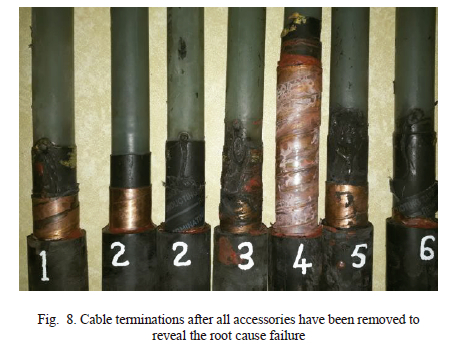
The technical expert on cable terminations and accessories from the Original Equipment Manufacturer (OEM) was consulted to provide expert advice to determine the root cause of failure. All cable terminations were handed over to be dissected for closer examination and assessment once the experiment was completed. It remained important to consider and include the opinion and explanation of an expert to ensure experimental results obtained can relate to practical field experience and observation.
Very specific components and material make up the entire cable termination kit. It is important to understand the function and purpose of each individual component and the possible defect it could create if not properly installed. Figure 7 represents some detail on how the termination is progressively made by applying the various components at each stage [28].
The subjective analysis was done to create a ranking order of defects from most significant to serious. This was done taking the type of defect or workmanship error of the five artificial cable terminations defects into account. The ranking could be listed as follows in descending order:
Most significant defects: Terminations 4: Incorrect position of the stress control. Effectively, the stress control tube is conductive-resistive and creates immediate tracking as soon as the termination is energized because the tube is close to the lug. This type of defect is very common and one of the major reasons for termination failure.
Very Significant defects: Terminations 5: No mastic applied at the stress control tube. This defect is weakening the termination and forces the stress control tube to be exposed to the radial distribution in the longitudinal stresses. Although this mistake is not so common in industry, it remains critical especially on higher voltage from 33kV.
Significant defects: Terminations 3: Damage to XLPE insulation. The cuts were circumferential and not longitudinal. The latter is known as tramline cuts and are commonly found in industry when poor workmanship was evident. It remains critical to maintain the integrity of the XLPE insulation in all directions during cable handling and installation.
Very serious defects: Terminations 6: Incorrectly earthing system. In most cases earthing on both sides of cables could result in circulating current which causes overheating at the termination earth resulting in failure. Although not so common root cause failure, excessive heating in the termination will result in failure.
Serious defects: Terminations 2: Screen cut damage. The jointer made use of a "Stanley" knife to create the circular cut to remove the semi conductive screen. Work in this area of the termination is in the high stress area and requires careful and precision workmanship. Closer examination of the termination revealed that the semi conductive layer was loose from the XLPE insulation with signs found of the actual screen cut into the XLPE. If the cut had been deeper into the insulation, the defect would have been more serious with increased in ranking to number 1 or 2. The mastic that was applied in this area compensated for the defect to some extent and the termination was now relying more on the accessories. It was observed and recorded that the "no defect" side of the cable sample actually failed before the "defective" side on Termination 2.
No defects and good workmanship: Terminations 1: This termination was made with the best workmanship and in accordance with the associated instruction.
VI. Concise Discussion On The Outcome Of The Experiment And Interpretation Of Overall Results
A. Comparison On The Failure Ranking Outcome
The actual termination failure sequence (Table IV) is compared against the PD trending information as well as the assessment from the industry expert. As expected, there is good correlation between failure sequence and the pD trending as detection of higher magnitudes of pD typically supersedes complete breakdown of insulation. There is a 66% match against the unconventional pD system. There was a minor mismatch in ranking on Termination 2 and 4.
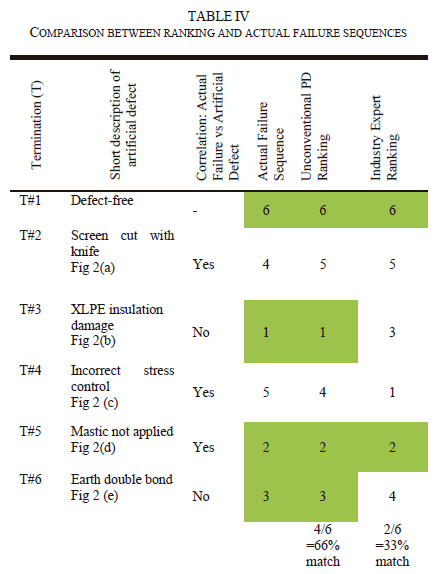
It is also important to really assess the true cause of failure as the intended artificial defect for each type might not have been the reason for failure. Two artificial defects, namely XLpE insulation damage and earth double bond, did not significantly contribute towards the failure. The industry expert concluded his ranking based on the description of the artificial defect as well as the dissection (Figure 8) afterwards without knowing the true sequence failure. It is believed that the ranking would have been different and much better if the expert was also involved when the original artificial defects were applied. Furthermore, this approach to compare the assessment from the technical expert against measured data is uncommon and no literature could be found on similar tests conducted.
B. Tan Delta Results Interpretation
The mean and standard deviation measurements on Termination 3 clearly displayed serious concern even from Period 1. It progressively worsens until failure only after 16 days. Although meaningful correlations and comparisons could be made from the dataset, it was difficult to propose a ranking sequence because the dataset consists of 3 parameters and were only taken on four instances during the duration of the experiment. The short length of cable also resulted in higher measurements.
C. Effective Cable Accessories Assessment Standard
The most reliable test standard remains a single acceptable test procedure similar to SANS1053 [29] and SANS 10198 [10], and not a guide type document such as the IEEE 400 series. Guide type documents typically include all commercially available technology and confirm test result comparability to known performance expectations and ensure test accuracy and values [2]. These standards contribute enormously to the understanding and application of test procedures and technology but might not be sufficient to ensure acceptable workmanship.
VLF withstand testing is an acceptable test method although extensive research revealed that many cable systems fail within the first 3 years after commissioning. For this experiment, VLF withstand test was not done because the preferred age acceleration mechanism was restricted to the 50Hz source. The VLF TD at a maximum of 2.5Uo was done but for short durations. It is however noted that both Terminations 1 and 4 successfully withstood the VLF at 2.5Uo test, although only for few minutes and not the full duration of 60 minutes as prescribed by the standard.
SANS 1053 stipulates that an ac voltage withstand test be conducted on accessories for 1 minute at 4Uo and 4.5Uo for 5 minutes. The requirement is that no failure or flashover occurs. It is noted that 3 terminations failed shortly after the voltage was increased from 3.5Uo to 4.5Uo. Termination 4 was able to withstand the 4.5Uo voltage for almost 2 days, only to fail at 5.5Uo. This emphasized that the SANS 1053 withstand test might not be adequate to detect workmanship defects.
VII. Conclusion
Aging and deterioration of the cable terminations were successfully accomplished with a 50Hz power frequency source. It is remarkable that the XLPE insulation and some terminations withstand the higher voltages up to 5.5uo. Even at higher voltages a considerable long duration of many days was required before the insulation failed and voltage breakdown occurred. Most of the terminations failed when the voltage was increased from 3.5Uo to 4.5Uo which corresponds to the applied voltage for maximum withstand test.
VLF Tan Delta (DT) as an electrical acceptance test proved to be an easy and effective test method to assess the condition of cable system and can be used specifically for cable terminations. The specific indicators, namely the mean and differential of Tan Delta (respectively TD and DTD), appear to be useful indicators to reveal insulation deterioration. The Tan Delta Temporary Stability (TDTS) or time stability of TD reveals hidden information on the condition and aging of the insulation and can be used as reliable indicator together with the newly developed skirt indicator. It was, however, difficult to use any one or combination of the parameters to visually trend the progressive deterioration of the insulation. The color-coding approach to visually present the data was more useful.
Two PD sensors were successfully used to measure the partial discharge on the cable terminations. Both HFCT and coupler sensor proved to have exceptional sensitivity to clearly indicate significant increases in PD activity. The placement of the coupler sensor in near proximity of the cable termination corresponds well with the intended purpose to detect local PD and was the preferred sensor for the experiment due to excellent measuring bandwidth.
The on-line trending Dynamic Ratings application with visual representation and viewing of various channels are an effective way to compare various cable systems, as well as individual assessment of terminations. Early warning increase in PD activity corresponds well with actual termination failure and significant increases in trending values were noticeable prior to termination failure. This makes unconventional partial discharge technology an attractive method for cable termination assessment. The utilization of unconventional PD test methods is recommended to further improve cable system acceptance testing and this should be promoted to eventually developed into industry standards for condition assessment of cable systems. The unconventional PD measuring system had a success rate of 66% in determining the correct sequence of termination failure. Unconventional PD acceptance levels for cable terminations should be developed with an attempt to improve and guarantee workmanship.
The most critical part in any medium voltage cable termination remains the interface between the semi conductive layer with the XLPE insulation. All six cable terminations eventually failed in this electrical high stress area. Good workmanship together with precision work is required to ensure high quality work with guaranteed product performance. The detection of partial discharge in this critical area by the unconventional measurement method should improve quality assurance to ensure the estimated minimum lifetime of 30 years can be achieved to contribute towards reliable distribution systems.
VIII. Acknowledgements
The author gratefully acknowledges the following institutions and people for contributing and making this research possible:
Erongo Regional Electricity Distributor (Namibia) for giving the opportunity to study and conduct research.
City Power (South Africa), in particular Mr Patrick O'Halloran together with the entire team, for making the high voltage laboratory and test equipment available for the experimental execution. Mr O'Halloran was employed at City Power at the time the experiment was conducted.
Airshrink-CiP (Airshrink Cable Installation Products, South Africa), Mr Jan Hattingh for donating all the cable terminations and Mr Christo van den Berg who provided technical advice and dissected the failed terminations. Mr Van den Berg was employed at Airshrin-CiP at the time the experiment was conducted.
Martec (South Africa), the late Mr John Sherriff and Mr Juan Laubuschagne, who provided all partial discharge and Tan Delta testing equipment, executed the tests in the laboratory and provided reports and data.
Mr Nandes de Lange (was final year student at the North West University, South Africa when experiment was conducted) for assistance during the set-up and execution of the tests.
References
[1] D. Byrne, S. Thomas, R. Hummel, B. Lanz and c. Shannon, "Cable system commissioning update," in International Conference on Insulated Power Cable, Versailles, 2019.
[2] B. Lanz, S. Ziegler and G. Hafner, "Ensuring future reliability using manufacturers' standards to assess cable system performance after Installation," in International Conference on Insulated Power Cables, Versailles, France, 2015.
[3] IEEE400, "Guide for field testing and evaluation of the insualtion of shielded power cable systems rated 5 kV and above," IEEE, 2012.
[4] IEEE400.3, "Guide for Partial Discharge testing of shielded power cable systems in a field environment," IEEE, 2006.
[5] IEC60270, "High voltage test techniques: Partial discharge measurement," British Standard, Brussels, Belgium, 2001.
[6] IEEE62478, "High voltage test techniques -Measurement of partial discharges by electromagnetic and acoustic methods," IEEE, 2016.
[7] C. Suwanasi, T. Suwanasri, P. Fuangpian and S. Ruankon, "Investigation on Partial Discharge of power cable termination defects using high frequency current transformer," in International Conference on Electrical Engineering/Electronics, Computer, Telecommunications and Information Technology, Krabi, Thailand, 2013.
[8] D. A. Fynes-Cinton, D. R. Cornish and C. Nyamupangedengu, "Partial Discharge patters of typical installation defects in Medium Voltage power cable terminations," in International symposium on high voltage engineering, Pilsen, Czech Republic, 2015.
[9] T. Czaszejko and J. Sookun, "Acoustic emission from partial discharges," in ISEIM International Symposium on Electrical Insulating Materials, Niigata City, Japan, 2014.
[10] SABS, "SANS 10198: The selection, handling and installation of electric power cables of rating not exceeding 33 kV," South African Bureau of Standards, Pretoria, South Africa, 2016.
[11] SANS1339, "Electric cables - Cross-linked polyethylene (XLPE) insulated cables for rated voltages 3,8/6,6kV to 19/33kV," SABS, Pretoria, South Aftica, 2009.
[12] IEC60502-1, "Power cables with extruded insulation and their accessories for rated voltages from 1 kV up to 30 kV," International Electrotechnical Commission, Geneva, Switzerland, 2004.
[13] IMCORP, "The case for a standardized commissioning test," Imcorp, Manchester, UK.
[14] S. Jespers, M. Vanossi and M. Green, "The use of after installation commissioning tests to assure MV power cable systems meet manufacturers' standards," in International Conference on Insulated Power Cables, Versailles, France, 2011.
[15] IMCORP, "Manufacturers' standards and online PD testing: Comparative analysis with the factory grade test," Imcorp.
[16] J. Drapeau, "Proposition of new diagnostic features for VLF Tan Delta measurements in order to improve their interpretative value," in International Conference on Insulated Power Cables, Versailles, France, 2019.
[17] A. Gerstner, "VLF sine 0.1Hz - Universal voltage source for testing and diagnostics of medium voltage cable," Bauer, Sulz, Austria, 2016.
[18] IEEE400.2, "Guide for field testing of shielded power cable systems using Very Low Frequency (VLF) (less than 1 Hz)," IEEE, 2013.
[19] T. Sandri, "Acceptance and maintenance testing for medium voltage electrical power cables: exploring technology developments over the past 20 year," in International Conference of Doble clients, Watertown, USA, 2015.
[20] W. G. D1.37, "Techncial brochure, Guide for partial discharge detection using conventional (IEC60270) and unconventional methods," Cigre, Paris, France, 2016.
[21] L. Renforth, M. Seltzer-Grant, R. Mackinlay, S. Goodfellow, D. Clark and R. Shuttleworth, "Experiences from over 15 years of on-line partial discharge (OLPD) testing of in-service MV and HV cables, switchgear, transformers and rotating machines," in IX Latin American Robotics Symposium and IEEE Colombian Conference on Automatic Control, Bogota, Colombia, 2011.
[22] S. Holmes, J. Caruana and S. Goldthorpe, "Low cost continuous monitoring of partial discharge activity in MV substations," in 20th International Conference on Electricity Distribution, Prague, Czech Republic, 2009.
[23] A. Cuppen, E. F. Steennis and P. C. Van der Wielen, "Partial Discharge Trends in Medium Voltage Cables measured while in-service with PDOL," in IEEE, New Orleans, USA, 2010.
[24] D. Kim, Y. Cho and S. Kim, "A study on three dimensional assessment of the aging condition of polymeric medium voltage cables applying Very Low Frequency (VLF) tan 5 diagnostic," IEEE Transactions on Dielectrics and Electrical Insulation, vol. 21, no. 3, pp. 940-947, 2014. [ Links ]
[25] M. Luitel, "Statistical approach for predicting remaining life of cross-linked polyethylene insulated cables," Tribhuvan University, Nepal, 2005.
[26] IEEE1407, "Guide for accelerated aging tests for Medium Voltage extruded electric power cable using water filled tansk," IEEE, 1998.
[27] Knenicky and M, "Partial Discharge patters during accelerated aging of medium voltage cable system," in IEEE International Conference on High Voltage Engineering and Applications, Prague, Czech Republic, 2018.
[28] C. I. P. CIP, "Installation instruction heatshrink termination kit for single core individualy screened XLPE armoured and un-armoured cables," Airshrink, CiP, South Africa, 2008.
[29] S. A. Standards, "SANS 1053:2010/NRS053:2008 Accessories for medium voltage power cables (3,8/6,6 kV to 19/33 kV," SABS Standards Division, Pretoria, South Africa, 2010.
1 City Power is an electricity utility in the Gauteng province of South-Africa
2 Erongo RED is an electricity utility in the Erongo Region of Namibia
J. Vermaas Bissett was born in Kuruman, Northen Cape, South-Africa in 1970. He received his Bachelor's degree in Electrical and Electronics Engineering at the University of Pretoria, South-Africa in 1996, and then completed his Honours degree in Technology Management in 2003, at the same university. In 2021 he completed his Master of Engineering in Electrical and Electronic Engineering at North-West University, South Africa.
He held various engineering positions at larger electricity utilities like the City of Tshwane, Cape Town, and Windhoek. He is currently the Chief Engineer at Erongo Regional Electricity Distributor in Walvis Bay, Namibia.
Mr Bissett is registered as a Professional Engineer at the Engineering Council of Namibia.

Pieter A. van Vuuren (M 2014) was born in Krugersdorp, South Africa in 1974. He received the Ph.D. degree in computer and electronic engineering from the North-West University in 2010.
From 2010 to the present, he has been part of the faculty of Engineering of the North-West University. His research interests include pattern recognition and machine learning applied to condition monitoring, agriculture and skills development.

Prof J.J. (Jerry) Walker is a Fellow of the South African Institute of Electrical Engineers. He completed a DTech degree at Vaal University of Technology, Vanderbijlpark, South Africa. The title of Doctoral thesis was: "Diagnostic Evaluation of Water Tree Aged Cross-Linked Polyethylene Insulated Cables."
He started his career as an Apprentice Millwright and progressed during his career as an Artisan, Technician, and a Lecturer at Vaal University of Technology. He eventually became the Head at the Institute for High Voltage Studies at VUT. After retirement from VUT in 2006, he worked as a consultant at Walmet Consultancy (Pty) Ltd as well as part time Research Professor at Vaal University of Technology until the end of 2023.
Prof Walker published and presented several papers at national and international conferences.

