


Services on Demand
Article
 English (pdf)
 Article in xml format
 Article references
Indicators

Related links
-
 Cited by Google
 -
 Similars in Google
Share

 Permalink
SAIEE Africa Research Journal
On-line version ISSN 1991-1696
Print version ISSN 0038-2221
SAIEE ARJ vol.115 n.1 Observatory, Johannesburg Mar. 2024
Self-Synchronizing On-Off-Keying Visible Light Communication System For Intra- and Inter-Vehicle Data Transmission
S. AchariI; A.Y. YangII; J. GoodheadII; B. SwanepoelII; L. ChengIII
ISchool of Electrical and Information Engineering, University of the Witwatersrand, Johannesburg, Gauteng, 2050, South Africa (Shamin.Achari@wits.ac.za)
IISchool of Electrical and Information Engineering, University of the Witwatersrand, Johannesburg, Gauteng, 2050, South Africa
IIISenior Member, IEEE. School of Electrical and Information Engineering, University of the Witwatersrand, Johannesburg, Gauteng, 2050, South Africa (Ling.Cheng@wits.ac.za)
ABSTRACT
Visible light communication is a present technology which allows data to be transmitted by modulating information onto a light source. It has many advantages over traditional radio frequency communication and up to 10,000 times larger bandwidth. Many existing research in visible light communication assumes a synchronized channel, however, this is not always easily achieved. This paper proposes a novel synchronized VLC system with the potential to ensure reliable communication in both intra- and inter-vehicle communication. The protocol achieves synchronization at the symbol level using the transistor-transistor logic protocol and achieves frame synchronizations with markers. Consequently, the deployment of the system in both intra- and inter-vehicle communication may present numerous advantages over existing data transmission processes. A practical application where visible light communication is used for media streaming is also previewed. In addition, various regions of possible data transmission are determined to infer forward error correction schemes to ensure reliable communication.
Index Terms:Asynchronous Communication, Visible Light Communication, Vehicle To Vehicle, Wireless Communications
I. Introduction
Visible Light Communication (VLC) works on the same principles as optical wireless communication and is composed of three main parts: the transmitter, the channel or medium, and the receiver. The transmitter modulates data onto the visible light spectrum through a Light Emitting Diode (LED) or other light source. The channel is the free space between the transmitter and receiver. The receiver uses photodiodes or other optical detection devices such as camera lenses to identify the transmitted signals [1]. This concept is not only limited to the visible light spectrum but is easily extended to the infrared and ultraviolet regions as well. The mainstream idea of VLC is primarily brought about due to the advancements in the manufacturing of LEDs as newer LEDs allow for high modulation speeds, which provide up to Gbps communication [2]. VLC promises significant advantages over traditional Radio Frequency (RF) communication as there is less health risk involved in communication, there is approximately 390 THz of unlicensed bandwidth, and there are additional security measures thanks to the required Line of Sight (LOS) transmission [3], [4]. In addition, for applications such as underwater communication, VLC is a strong candidate as RF communication is strongly attenuated by water [3], [5]. As the Internet of Things (IoT) paradigm makes headway, more subsets of research are explored, such as the Internet of Vehicles (IoV), where vehicles will exchange information with other surrounding vehicles (V2V), as well as to buildings, and infrastructure (V2I) [6]. VLC will greatly impact short-distance communication in IoT and IoV as it can be used to improve the performance of traditional vehicular networks when used as a supplementary transmission channel, as shown in [6].
With all the advancements in hardware sensors and processing power, vehicles have seen a rise in the amount of data transmitted within themselves. From anti-braking systems to stability control, even tire pressure sensing and radar or cameras are being incorporated into vehicles [7]. All these systems need to transmit data to the central processing unit, increasing vehicle wiring requirements and complexities. The main form of wireless communication used with many vehicles today is Bluetooth communication, however, the fundamental use of this is for infotainment [7]. Furthermore, VLC has mainly been used for inter-vehicle communication and V2I communication. In contrast, more needs to be said about the possibilities of employing VLC as a communication medium within the constraints of individual vehicles. Additionally, since VLC does not work in the RF spectrum, many interference issues in communication devices and instrumentation are avoided altogether. Hence, VLC is a perfect candidate for intra-vehicle communication.
Most research in the field of VLC tends to focus on achieving faster transmission speeds or producing multiple carrier schemes, while few describe synchronization techniques for such systems. Wang et al. achieved speeds of 3.25 Gbps communication using a 512 QAM modulation and single carrier frequency domain equalization techniques [8]. Employing wavelength division multiplexing and discrete multitone modulation, Vucic et al. produced a VLC system which can reach average speeds of 803 Mbps across a single LED [9]. Various hardware improvements are employed to gain more significant data rates. For example, McKendry et al. use special violet micro LEDs and orthogonal frequency division multiplexing modulation to achieve speeds of up to 3.32 Gbps modulated on a single LED [2]. Unique improvements to VLC systems are shown in [10] where Chow et al. use the rolling shutter effect of a standard CMOS smartphone camera to increase the data rates by up to 60 times to gain a maximum data rate of 1.68 Kbps.
Frame synchronization in VLC systems is achieved by either adding packet numbers, using marker codes, or extended prefix synchronization codes, as shown in [11]. Comma-free codes, number theoretic codes, and watermark codes have traditionally been implemented to protect against synchronization errors at a symbol level, either by detection or correction. Alternatively, another layer of synchronization is obtained at the signal level using techniques such as Phase-Locked Loops; however, this is beyond the consideration of this paper.
This paper aims to introduce a self-synchronizing VLC scheme that achieves synchronization at the symbol level using the Transistor-Transistor Logic (TTL) protocol and achieves frame synchronizations with markers. The novelty and main contribution come from the frame synchronization techniques used in conjunction with the TTL protocol in the context of a VLC system. The system shows the possible potential to be easily deployed within an automobile or airplane, which will provide communication within the vehicle. In addition, various regions of possible data transmission are determined with the intention of inferring Forward Error Correction (FEC) schemes to ensure reliable communication.
The layout of this paper is as follows: Section II discusses the background of the TTL serial communication protocol, On-Off-Keying (OOK) modulation, channel errors and current intra- and inter-vehicle communications. The system boundaries, limitations and assumptions are given in Section III along with the components and hardware designs of the proposed system. Section IV elaborates on the methodology and testing procedure. The results are presented with a detailed analysis using various parameters in Section V. The advanced media streaming configuration is presented in Section VI. Finally, the conclusion is given in Section VII.
II. Preliminaries
A. TTL Serial Communication Protocol
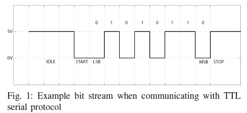
The TTL serial communication protocol provides asynchronous communication; thus, no clock signal is transmitted. The communication speed and other parameters, such as parity and number of data bits, must be agreed upon beforehand by both the transmitter and receiver. The TTL serial protocol encompasses its data bits (7 or 8 bits) between a start bit and by either one or two stop bits. Data is transmitted with the least significant bit first, and lastly, parity bits (even, odd, mark or space) may be added if desired. In TTL serial communication, a 1 is represented as either 3.3V or 5V, depending on the hardware device used, while 0V represents a 0. Fig 1 shows an example bitstream when the number 106 (0110 1010B) is transmitted with no parity bits using the TTL serial protocol. This TTL serial protocol with its start and stop bits introduces synchronization errors.
B.On-Off-Keying (OOK) Modulation Scheme
Modulation schemes allow information to be encapsulated in a specific manner in order to be transmitted. OOK, pulse position modulation, inverse pulse position modulation and variable pulse position modulation are all examples of time domain modulation schemes [12]. OOK is the simplest modulation method and is a form of binary signal modulation. In VLC-OOK, a 1 is defined by turning on an LED for a period of T seconds, whereas a 0 is represented by switching the LED off for T seconds [12]. OOK modulation is used in this setup as the TTL protocol signal can be easily modulated onto the LED with no additional processing.
C.Synchronisation Errors
The errors that occur in asynchronous communication include insertion, deletion and substitution errors where insertion and deletion errors make up synchronization errors [13]. Insertion errors could occur when the receiver samples too fast (over-samples) and add more symbols to the received data stream. Deletion errors occur when the receiver samples too slow (under-samples) and removes symbols from the transmitted data stream [13]. Substitution errors occur when a received symbol is transformed to another symbol of that alphabet [13].
D.Intra- and Inter-Vehicle Communications
Inter-vehicle communications between vehicles on highways are generally used to increase road safety and reduce traffic congestion [14]. It has been further employed to assist human operators by providing communication between the sensors and systems for synchronized operations [15]. There is a multitude of research that involves the use of VLC in V2V and V2I communications. [16], [17] provide surveys on such a topic. Channel modeling for inter-vehicle VLC in various weather conditions and road types are given in [18] and [19], respectively. Realized inter-vehicle VLC systems are presented in works such as [20]-[22] to name a few. Narmanlioglu et al. [23] conducted an investigation into the viability of VLC in inter-vehicular connectivity for both point-to-point vehicular VLC and decode-and-forward relaying based cooperative vehicular VLC. Far less is said about the use of VLC for intra-vehicle communication. [24] et al. is one such piece that looks at utilizing VLC for in-vehicle communication. Here, data is distributed to various areas of the vehicle using fibre optics before the free space channel. The main drawback, however, is the use of protocols such as SPI and I2C, which assume synchronized communication as they require clock signals to be transmitted. Generally, these clock signals would be wired, reducing the effectiveness of utilizing VLC.
Traditional techniques for intra-vehicle communication are performed over Control Area Network (CAN) and FlexRay networks for Electronic Control Units (ECUs) installed into vehicles [15], [25], [26]. The most up-to-date intra-vehicle communication is performed over an ethernet network. In the ethernet network, the physical layer is crucial as it is the physical material employed to transmit information to and from a centralized location. In the physical layer, there are two standards: automotive-specific and non-automotive-specific. The automotive-specific standards are specifically tailored for intra-vehicle communications [27]. Popular automotive-specific standards are CAN, FlexRay, and local interconnect network. For non-automotive specific, popular standards are low-voltage differential signaling, which is constructed with twisted-pair copper cable for high-speed signaling transmission. Alternatively, Firewire is another commonly utilized non-automotive specific standard, in which it communicates through the use of video cameras in computer communication bus standards [28], [29].
The traditional techniques proved reliable for the communication of bus systems. However, it presented problems through the number of ECUs required to connect to the system over time. Consequently, the increase in ECUs and connections meant it monopolized a significant amount of bandwidth. Thus, the architecture of traditional techniques is rendered inefficient for modern networks, particularly for the driver assistance system. With the various number of sensors utilized for vehicle assistance operation, the number of wired connections between sensors and systems becomes cumbersome. It requires space to be reserved for wire placements. Consequently, the number of wires adds to the vehicle's overall weight.
In addition to intra- and inter-vehicle communication, Wireless Avionics Intra-Communications (WAIC) is introduced to communicate between single points within aircraft [30]. WAIC utilizes radio communication for the transmission of data between two points. The purpose of WAIC is to reduce the redundancy of wired connections within the aircraft. Wireless connections reduce the overall weight of the aircraft, as wired connections for modern airplanes are approximately 500 kilometers in length, with an estimated weight of 7,400 kilograms for the Boeing 787 [30], [31]. As a result, a wireless system will increase fuel efficiency and simplify the wiring within the aircraft.
III. An Original Intra- and Inter-Vehicle VLC System Synchronised With the Transistor to Transistor Logic Protocol and Markers
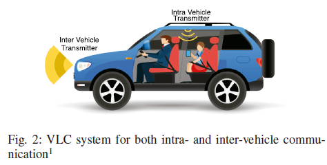
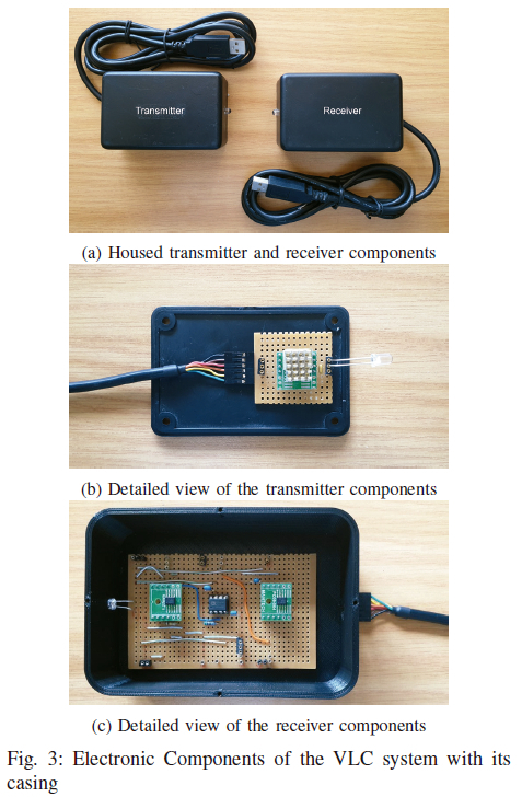
A new VLC system for potential wireless vehicular communication is illustrated in Fig 2, where existing light sources are employed for intra- and inter-vehicle communication. This setup uses the TTL serial transmission protocol and OOK to transmit data asynchronously. This system is illustrated in Fig 3. The transmitter and receiver with its housing are shown in Fig 3a, Fig 3b and 3c present the intricacies inside both transmitter and receiver, respectively.
A. Use in Vehicular Communication
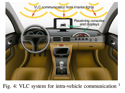
The compact size and ease of access to information of this VLC system allow it to be easily deployed within any vehicle to provide data communication. The main benefit of using a VLC system for intra-vehicle data transmission is the fact that it reduces the overhead and complexity that its wired counterpart shares. The implementation concept of the VLC system for intra-vehicle communication is shown in Fig 4. Intra-vehicle communication has the potential to be extended to airplanes as WAIC to simplify wired connections. The implementation of this system would vastly reduce the overall weight of the aircraft. The system employs the same concept as intra-vehicle communication and can work without the use of visible light by simply utilizing the infrared spectrum and infrared LEDs.
B. Transmitter
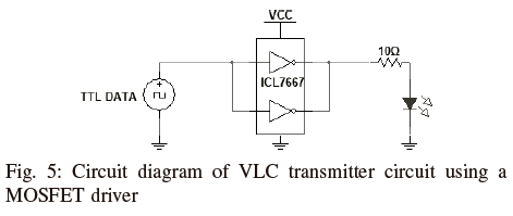
The transmitter circuit diagram is shown in Fig 5 and is responsible for transmitting the TTL serial data. It consists of a USB to serial cable, allowing for easy connection to a microcontroller, which would then communicate to the vehicle's processing unit. For the prototype and testbed, a laptop is used to generate the data and acts as the vehicle's processing unit, which greatly simplifies the method. This data is then propagated to an analog circuit containing an LED that modulates the data using OOK. A MOSFET or LED driver is used as the switching device as it allows for high data rates while supplying the required current for a high-powered LED.
C. Receiver
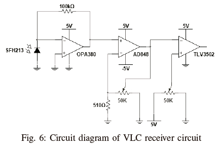
The receiver is responsible for capturing the variations in light intensity, determining a binary stream from these fluctuations and then transmitting this binary stream to the vehicle's data processing system. Again, for the testing of this design, a laptop is used as the processing subsystem to simplify the procedure. A PIN photodiode is used to capture the light intensity, producing a current proportional to the intensity of the light that falls on it. A Transimpedance Amplifier (TIA) is then used to convert the current produced by the photodiode to a voltage. Preliminary tests proved that using a single TIA to convert current and amplify the signal is inadequate, as a trade-off between the gain and bandwidth is seen in the op-amp. For this reason, two separate steps are used, one for capturing the light signal and the other for amplifying the signal. As an additional measure, the signal must be conditioned using a comparator to ensure a perfect representation of the TTL data is produced. The receiver circuit uses the SFH213 photodiode [32], along with the OPA380 and a 100KΩ feedback resistor shown in Fig 6. The combination of these components provides a maximum transimpedance bandwidth of approximately 3MHz, as the SFH213 has an internal capacitance of 11pF. The SFH213 has an extensive detection wavelength range of 400nm to 1100nm. This indicates that any color LED, including white, may be detected. We reemphasize that the hardware and component parameters and choices may be further optimized, but it is beyond the scope and purpose of this paper.
IV. METHODOLOGY
A. Test Procedure
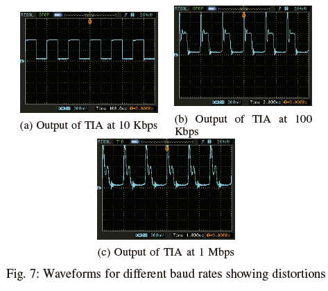
The transmitter and receiver are placed in a covered, black polystyrene box at a distance of 15cm from each other. The distance of 15cm ensures the photodiode detects no reflections and multipath signals. Any distance exceeding approximately 20cm starts to introduce multipath reflections. This phenomenon is further explained in Section IV-B. It is assumed that reflections and Non-Line of Sight (NLOS) signals are negligible in the practical system as the system will operate ideally in open free space where reflections are minimized. In addition, the covered box is used to ensure the consistency of the parameters during tests. This allows the tests to be conducted at any time of the day without the issue of varying ambient light. The system, however, remains operational in open free space without the box. Various Signal to Noise Ratio (SNR) values are achieved by adjusting the transmitter's power, which is analogous to increasing or decreasing the distance between the transmitter and receiver. The SNR values used are an approximation and elaborated in Appendix A. The SNR values used are evaluated at a baud rate of 10Kbps to ensure little to no distortion is present at the output of the TIA. Fig 7 demonstrates the distortion of signals at the TIA for various baud rates. A combination of parameters are tested at each SNR value, and these include baud rates (10Kbps, 50Kbps, 100Kbps, 250Kbps, 500Kbps, 750Kbps, 1Mbps), frame length (1003 symbols, 5003 symbols, 10003 symbols) and synchronization symbol length (1 symbol, 5 symbols, 10 symbols).
The baud rates are chosen to span an effective range while not exceeding the hardware capacity, as the USB to TTL only allows a maximum of 3Mbps. The payload for the frame is a pseudo-random generated string of ASCII symbols that fall in the range of 64 to 126 (@ to ~). Each frame contains the same payload to allow for a more straightforward analysis; however, a frame ID of three symbols is added to the front of each packet. A synchronization word is fixed to the beginning of each frame. In this case, it is a varying number of $ symbols. This synchronization symbol does not appear in the payload.
A maximum time of 60 minutes for transmission for a given set of parameters is used. If no substitution errors occur within the first 15 minutes of transmission or no packets are dropped, the transmission ends as the communication is assumed to be in a perfect channel with no appreciable errors, and a new set of parameters are chosen. If at least 100 packets with substitution errors or 100 packets are dropped, the transmission also ends, as this provides enough statistics for a given set of parameters. Any synchronization errors (when a received frame length is longer or shorter than the expected length) are analyzed as a dropped packet, while a missed frame is also categorized as a dropped packet. The frequency of substitution errors is recorded to infer a viable error correction scheme for a given set of parameters.
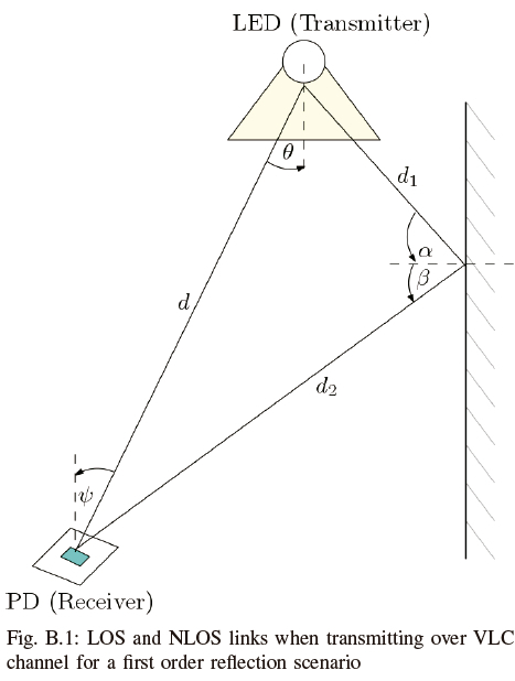
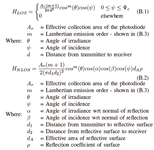
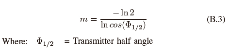
B. Line of Sight and Non-Line of Sight Detection
LOS is defined as a direct, uninterrupted link between the transmitter and receiver. In contrast, a NLOS uses diffuse reflections off surfaces to form an indirect link between the transmitting LED and the photodiode [33]. Using LOS increases the power efficiency of the channel while also reducing distortion from multipath signals, whereas using NLOS increases the robustness and practicality of the system as no direct link is required [33]. Fig B.1 in Appendix B illustrates the LOS and NLOS links that are used to transmit data via the LED to the photodiode. To make this paper more encompassing and self-contained, we have added theory and equations for the channel gain for both LOS, Hlos, (B.1), and NLOS, Hnlos, (B.2), in a first-order reflection scenario for the generalized Lambertian radiant intensity in Appendix B. This channel gain can essentially be used to determine the total power detected by the photodiode for both direct and reflected links by multiplying it by the transmit power which would traditionally be used in the SNR calculations. Due to the nature of the setup and available tools, the SNR calculations in this paper are approximations based on voltage measurements at the receiver.
The underlying TTL protocol relies heavily on timing, and thus, sampling at the correct instance is of the utmost importance. NLOS signals are minimized for the test procedure, as the NLOS signals are superimposed onto the LOS signal, which alters the overall received signal.
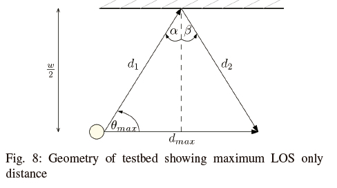
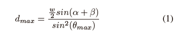
As stated previously, removing the NLOS signal replicates the real-world application scenario, as the transmitter and receiver pair will not be close to surfaces that cause the NLOS links. Fig 8 presents the testbed's geometry and the maximum allowed distance between the transmitter and receiver to ensure that only LOS links are detected. The setup has a width, w, of roughly 35cm and uses an LED with a full viewing angle of 120°. This means the maximum angle of incidence for the light rays, θmax, is 60°. After using the trigonometry and dimensions of the setup, it is found that d1 is equivalent to d2and dmax due to symmetry. Additionally, α+ ß is 60° in this case. This ultimately leads to a maximum distance, dmax of roughly 20cm between the transmitter and receiver, allowing only LOS signals to be detected. (1) describes a more generalized solution to calculate the maximum distance for only LOS signals to be detected.
V. Results and Analysis
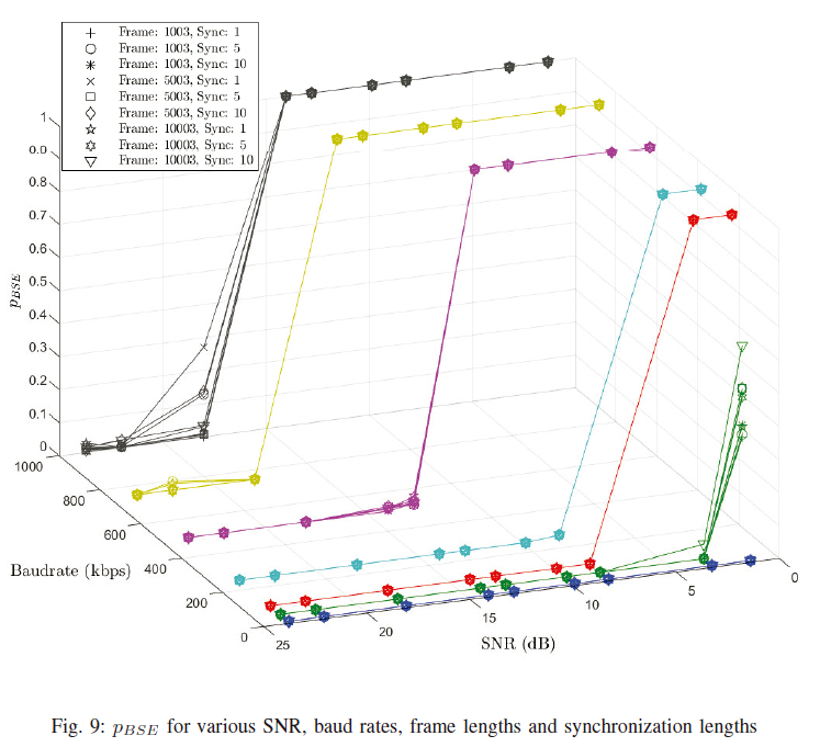
Fig 9 shows the block synchronization error rate, pBSE, obtained for various SNR and baud rates and different parameters of frame and synchronization lengths. pBSE is defined as the ratio of blocks that lose synchronization and the total number of transmitted blocks. A block synchronization error rate of 0 shows perfectly synchronized communication as all blocks or packets are received without synchronization errors. A block synchronization error rate of 1 implies a total loss of all packets transmitted. The inverse of the pBSE is defined as reliability which implies how well data transmission may occur without introducing synchronization errors. Reliability is characterised as (1 - pBSE). In Fig 9, most parameters' variations perform equally and tend to overlap, with major discrepancies only occurring at high baud rates or low SNR values. It is evident that lower baud rates allow for reliable communication at lower SNR values while increasing the baud rate tends to cause synchronization loss at these lower SNR values. Additionally, it is evident that synchronization errors are either catastrophic or cause very few dropped packets that are not in a viable error range to be corrected. In this case, an Automatic Repeat Request (ARQ) system is better suited for synchronization errors. Regions, where data transmission is viable, will still benefit from substitution FEC schemes, which can be deduced from the error frequency and reliability plots.
A.Effects of Synchronisation Length
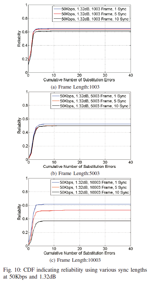
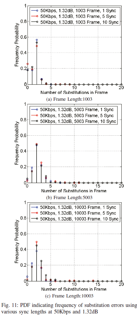
These results show the effects of changing the length of the synchronization words with respect to reliability as well as substitution errors in data transmission. From Fig 10a, it can easily be seen that a synchronization word of one symbol has the least amount of dropped packets, followed by five synchronization symbols and, lastly, ten. This is attributed to the fact that there is a lower probability associated with missing fewer consecutive symbols. If the system is treated as IID, as the synchronization word length increases, more packets are dropped as there is a higher probability of missing a synchronization symbol. Missing even a single synchronization symbol in the synchronization word will cause a dropped frame. However, the packets that are received at higher synchronization word lengths are more likely to be perfect or have very few substitution errors. This phenomenon can be seen in Fig 11a. This trend continues at higher frame lengths too. It is shown for a frame length of 5000 in Fig 10b and Fig 11b as well as a frame length of 10000 shown in Fig 10c and Fig 11c which shows the Cumulative Density Function (CDF) and Probability Density Functions (PDF) respectively.
B.Effects of Frame Length
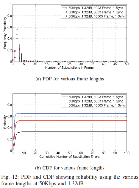
The following results show the effects of different frame lengths on the number of errors produced. The tests are performed at an SNR of 1.32dB, 50Kbps baud rate with a synchronization word length of 1 symbol. Frame lengths of 1003, 5003 and 10003 are tested, of which the error frequency is shown in Fig 12a and the reliability is shown in Fig 12b. These figures show that shorter frame lengths outperform their longer counterparts in both the dropped packet frequency and having more packets with fewer substitution errors. This intuitively makes sense and can be illustrated using an example. If the probability of causing an error (either insertion, deletion or substitution) is, for instance, 0.01% per symbol transmitted. We then have a chance of producing approximately 10 errors for the frame of 1003, 50 errors for a frame of 5003 and 100 errors for a frame of 10003. So as the frame length increases, the chances of affecting more symbols also increase; thus, more errors are introduced.
C. Effects of high SNR
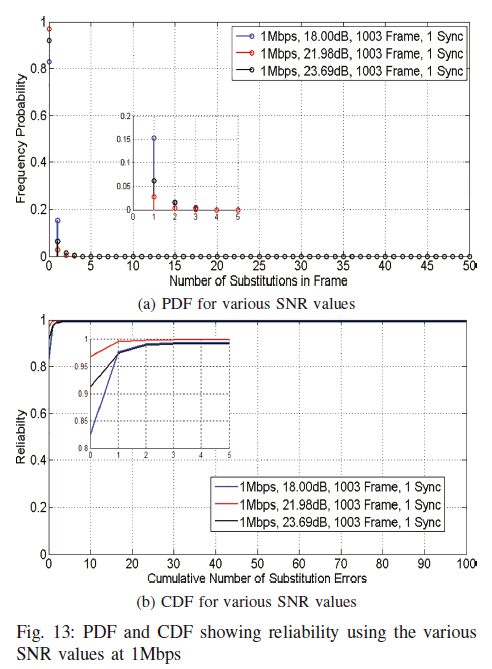
Intuitively higher SNR values produce fewer transmission errors, allowing higher baud rates to be achieved. After an SNR of approximately 18dB, there are no significant changes stemming from increasing the baud rate. Better results are then achieved by adjusting the comparator reference voltage. Fig 13a and Fig 13b show the substitution error frequency and reliability for the results of varying SNR while keeping all other parameters constant. These figures show that there are few effects achieved by increasing the SNR beyond 18dB. However, at the lower SNR values, the SNR heavily affects the dropped packets as well as the error probability.
D. Effects of Comparator Compensation
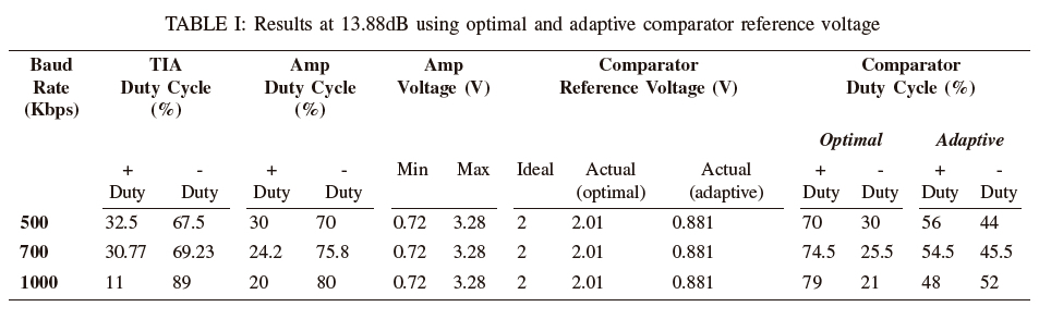
Increasing the baud rate for a particular SNR effectively reduces the duty cycle of the final signal output of the comparator, which is fed into the TTL cable. This, expectedly, causes errors as sampling points are incorrectly inferred or missed altogether. By adjusting the comparator value to trigger at a lower reference voltage, the overall duty cycle at the output can effectively be compensated for and essentially provide a much cleaner signal which will trigger the correct sampling by the TTL protocol. Table I shows both the unadjusted and adjusted duty cycles when using an ideal and adapted voltage reference for the comparator respectively. From this table, using a reference voltage lower than the optimal reference voltage produces duty cycles closer to 50% and thus allows for better data transmission. The improvement allows transmission from a once impossible communication state to a state that only requires an FEC and reduces the complexity of FEC for the states that previously required it.
VI. TTL OOK VLC system for Media Streaming
As an extension to the results and to prove the practicality of such a system, the VLC set-up, which uses the TTL protocol and OOK, is easily adapted to transmit video files over the visible light spectrum.
The transmitter and receiver circuit layouts are similar to what was presented earlier, with the only significant differences being that a 12Mbps USB-TTL cable is utilized instead of a 3Mbps cable; the comparator is changed to a Schmitt trigger to allow a smoother turn-on/ off range; lastly, a capacitor is added in series after the TIA to remove the DC offset. These minor adjustments in hardware immediately reap results as faster baud rates are now possible, leading to faster data communication. The media streaming system can reliably transmit video data at up to 4Mbps without any error correction schemes. Fig 14 shows the complete system used for media streaming applications. Here a live stream from the transmitting laptop is transmitted over VLC, and the captured data is shown on the receiving laptop. Again, laptops are used to act as the processing unit for demonstration purposes.
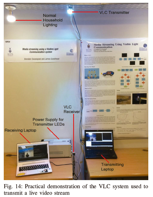
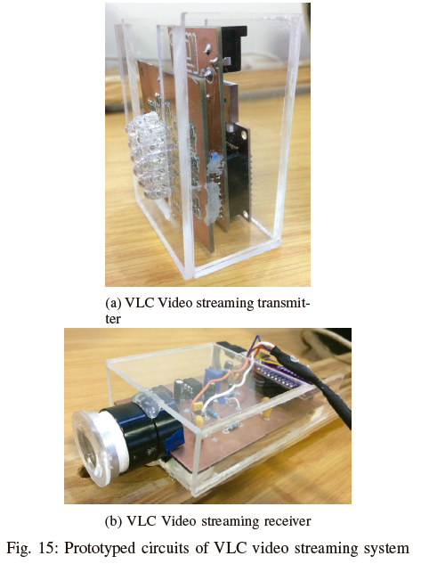
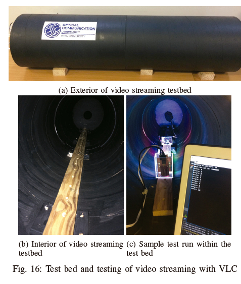
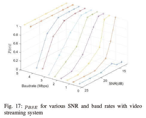
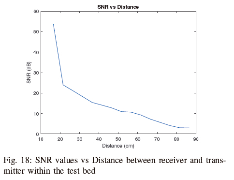
Fig 15a and Fig 15b show the final transmitter and receiver circuit used for the video streaming. The testbed exterior, testbed interior (with set spacings for the transmitter and receiver), and sample test operation can be seen in Fig 16a, Fig 16b and Fig 16c respectively. The main results from the video streaming tests and simulations are shown in Fig 17, where the effects of SNR and baud rate on the pbse can once again be observed. It can easily be seen that the trends follow previous tests of the basic system, and the analysis is performed similarly as before. The main differences are the higher baud rates achieved. Fig 18 additionally shows how SNR can be converted to the distance between the transmitter and receiver within the testbed (ideal conditions). It is worth noting that the lens on the media streaming receiver is removed for all tests. The addition of this can easily extend the distance between the transmitter and receiver to around 2m in the open-air real-life application scenario.
VII. Conclusion
It is possible to achieve reliable intra- and inter-vehicle communication using a self-synchronizing VLC system based on the TTL protocol and OOK modulation within specific regions and parameters. The system is small enough to be incorporated seamlessly into existing vehicle layouts while utilizing existing lighting sources. If the transmission is not perfect, FEC coding schemes may be used to improve the reliability of data transmission. These FEC schemes are for substitution errors and can be inferred from the frequency error distributions and reliability plots. For most error ranges, a simple ARQ protocol is opted for. A complete VLC transceiver is built and tested, allowing operating speeds in the range of 10Kbps to 1Mbps and SNR regions from 1.32 dB upwards. This is then improved for a video streaming application where up to 4Mbps data transmission is achieved without error correction techniques. Experimental results and data for tests show the effect of synchronization word length, frame length, SNR, and comparator reference voltage adjustment.
References
[1] S. Dimitrov and H. Haas, Principles of LED Light Communications: Towards Networked Li-Fi. Cambridge University Press, 2015.
[2] J. J. McKendry, D. Tsonev, R. Ferreira, S. Videv, A. D. Griffiths, S. Watson, E. Gu, A. E. Kelly, H. Haas, and M. D. Dawson, "Gb/s single-LED OFDM-based VLC using violet and UV Gallium nitride μLEDs," in Summer Topicals Meeting Series (SUM), 2015. IEEE, 2015, pp. 175-176.
[3] M. Bhalerao, S. Sonavane, and V. Kumar, "A survey of wireless communication using visible light," International Journal ofAdvances in Engineering & Technology (IJAET), vol. 5, pp. pp.188-197, 2013. [ Links ]
[4] E. Borgia, "The internet of things vision: Key features, applications and open issues," Computer Communications, vol. 54, pp. pp. 1-31, 2014. [ Links ]
[5] F. Akhoundi, J. A. Salehi, and A. Tashakori, "Cellular underwater wireless optical CDMA network: Performance analysis and implementation concepts," IEEE Transactions on Communications, vol. 63, no. 3, pp. pp. 882-891, 2015. [ Links ]
[6] A. Bazzi, B. M. Masini, A. Zanella, and A. Calisti, "Visible light communications as a complementary technology for the internet of vehicles," Computer Communications, vol. 93, pp. pp. 39-51, 2016. [ Links ]
[7] S. Tuohy, M. Glavin, C. Hughes, E. Jones, M. Trivedi, and L. Kilmartin, "Intra-vehicle networks: A review," IEEE Transactions on Intelligent Transportation Systems, vol. 16, no. 2, pp. pp. 534-545, 2015. [ Links ]
[8] Y. Wang, R. Li, Y. Wang, and Z. Zhang, "3.25-Gbps visible light communication system based on single carrier frequency domain equalization utilizing an RGB LED," in Optical Fiber Communication Conference (OFC), 2014. Optical Society of America, 2014, pp. 1-3.
[9] J. Vucic, C. Kottke, K. Habel, and K.-D. Langer, "803 Mbit/s visible light wdm link based on DMT modulation of a single RGB LED luminary," in Optical Fiber Communication Conference and Exposition and the National Fiber Optic Engineers Conference, 2011. Optical Society of America, 2011, pp. 1-3.
[10] C.-W. Chow, C.-Y. Chen, and S.-H. Chen, "Visible light communication using mobile-phone camera with data rate higher than frame rate," Optics express, vol. 23, no. 20, pp. pp. 26 080-26085, 2015. [ Links ]
[11] S. Schmid, G. Corbellini, S. Mangold, and T. R. Gross, "An LED-to-LED Visible Light Communication system with software-based synchronization," in IEEE Globecom Workshops, 2012. IEEE, 2012, pp. 1264-1268.
[12] S. Arnon, Visible light communication. Cambridge University Press, 2015.
[13] L. Cheng, "Coding techniques for insertion/deletion error correction," Ph.D. dissertation, University of Johannesburg, 2011. [ Links ]
[14] A. Uno, T. Sakaguchi, and S. Tsugawa, "A merging control algorithm based on inter-vehicle communication," in International Conference on Intelligent Transportation Systems, 1999. IEEE, 1999, pp. 783-787.
[15] S. Tuohy, M. Glavin, C. Hughes, E. Jones, M. Trivedi, and L. Kilmartin, "Intra-vehicle networks: A review," IEEE Transactions on Intelligent Transportation Systems, vol. 16, no. 2, pp. 534-545, April 2015. [ Links ]
[16] D. W. Matolak, "V2v communication channels: State of knowledge, new results, and what's next," in Communication Technologies for Vehicles: 5th International Workshop, Nets4Cars/Nets4Trains 2013, Villeneuve d'Ascq, France, May 14-15, 2013. Proceedings 5. Springer, 2013, pp. 1-21.
[17] A.-M. Cailean and M. Dimian, "Current challenges for visible light communications usage in vehicle applications: A survey," IEEE Communications Surveys & Tutorials, vol. 19, no. 4, pp. 2681-2703, 2017. [ Links ]
[18] M. Karbalayghareh, F. Miramirkhani, H. B. Eldeeb, R. C. Kizilirmak, S. M. Sait, and M. Uysal, "Channel modelling and performance limits of vehicular visible light communication systems," IEEE Transactions on Vehicular Technology, vol. 69, no. 7, pp. 6891-6901, 2020. [ Links ]
[19] H. B. Eldeeb, S. M. Sait, and M. Uysal, "Visible light communication for connected vehicles: How to achieve the omnidirectional coverage?" IEEE Access, vol. 9, pp. 103 885-103 905, 2021. [ Links ]
[20] J.-H. Yoo, J.-S. Jang, J. Kwon, H.-C. Kim, D.-W. Song, and S.-Y. Jung, "Demonstration of vehicular visible light communication based on led headlamp," International journal of automotive technology, vol. 17, pp. 347-352, 2016. [ Links ]
[21] Y. H. Kim, W. A. Cahyadi, and Y. H. Chung, "Experimental demonstration of vlc-based vehicle-to-vehicle communications under fog conditions," IEEE Photonics Journal, vol. 7, no. 6, pp. 1-9, 2015. [ Links ]
[22] F. A. Dahri, H. B. Mangrio, A. Baqai, and F. A. Umrani, "Experimental evaluation of intelligent transport system with vlc vehicle-to-vehicle communication," Wireless Personal Communications, vol. 106, pp. 1885-1896, 2019. [ Links ]
[23] O. Narmanlioglu, B. Turan, S. C. Ergen, and M. Uysal, "Cooperative MIMO-OFDM based inter-vehicular visible light communication using brake lights," Computer Communications, vol. 120, pp. pp. 138-146, 2018. [ Links ]
[24] C. Beguni, A.-M. Cailean, S.-A. Avătămăniţei, E. Zadobrischi, R. Stoler, M. Dimian, V. Popa, B. Béchadergue, and L. Chassagne, "In-vehicle visible light communications data transmission system using optical fiber distributed light: implementation and experimental evaluation," Sensors, vol. 22, no. 18, p. 6738, 2022. [ Links ]
[25] Robert Bosch GmbH, Specification, CAN, 9 1991, version 2.0.
[26] R. Makowitz and C. Temple, "Flexray-a communication network for automotive control systems," in IEEE International Workshop on Factory Communication Systems, 2006. IEEE, 2006, pp. 207-212.
[27] H. Kopetz and G. Grunsteidl, "TTP- A time-triggered protocol for fault-tolerant real-time systems," in The Twenty-Third International Symposium on Fault-Tolerant Computing (FTCS-23). IEEE, 1993, pp. 524-533.
[28] M. Rabel, A. Schmeiser, and H. Grossmann, "Integrating IEEE 1394 as infotainment backbone into the automotive environment," in IEEE Vehicular Technology Conference, 2001, vol. 3. IEEE, 2001, pp. 2026-2031.
[29] Y. Ke-You and X. Li-Hua, "Survey of recent progress in networked control systems," Acta Automatica Sinica, vol. 39, no. 2, pp. 101-117, 2013. [ Links ]
[30] O. Torres, T. Nguyen, and A. Mackenzie, "Enabling wireless avionics intra-communications," 2016.
[31] H. Canaday, "War on wiring," Aerospace America, vol. 55, no. 5, pp. pp. 24-27, 2017. [ Links ]
[32] Silicon PIN Photodiode, OSRAM Opto Semiconductors, 12 2015, version 1.3.
[33] J. M. Kahn and J. R. Barry, "Wireless infrared communications," Proceedings of the IEEE, vol. 85, no. 2, pp. 265-298, 1997. [ Links ]
This work is based on the research supported in part by the National Research Foundation of South Africa (Grant Numbers: 148765, 132651 & 129311).
1 Images adapted from Freepik.com, artwork originally designed by macrovector

Shamin Achari received a BSc degree in electrical and information engineering from the University of the Witwatersrand (WITS) in 2015. He is currently pursuing a PhD degree in electrical engineering at the University of the Witwatersrand Johannesburg, South Africa. His MSc was based in the field of Visible Light Communication with special focus on error correction schemes for visible light systems, which was subsequently upgraded to a PhD which mainly focuses on channel modelling and methods of correcting synchronisation errors. His research interests include visible light communications, machine learning and Internet of Things (IoT).

Alice Yi Yang holds a BSc.Eng in Electrical Engineering (Information) from the University of the Witwatersrand in 2016 and an MSc.Eng in Electrical Engineering in 2019, specializing in neural networks and pattern recognition for diagnosing fractures from medical images. Currently, she is a software engineer in the South African e-commerce industry.

James Goodhead received a BSc in Electrical Engineering from the University of Witwatersrand in 2019. From 2020 to 2023 he has been working for 3D Tactical Systems, a UAV manufacturing company in Cape Town, South Africa. He has gained experience working on long-range RF communication systems and antenna design. He is currently pursuing an MSc at the University of Cape Town in high-speed measurement techniques in conjunction with the Ithemba Labs and CERN.

Brendon Swanepoel received his BSc (Eng) in Electrical & Information Engineering from the University of the Witwatersrand in 2019. During that time, he specialised in Information Engineering with a particular interest in robotics. Since graduating, he has worked as a Software Engineering consultant.

Ling Cheng (M'10-SM'15) received the degree B.Eng. Electronics and Information (cum laude) from Huazhong University of Science and Technology (HUST) in 1995, M. Ing. Electrical and Electronics (cum laude) in 2005, and D. Ing. Electrical and Electronics in 2011 from the University of Johannesburg (UJ). His research interests are in Telecommunications and Artificial Intelligence. In 2010, he joined the University of the Witwatersrand where he was promoted to Full Professor in 2019. He serves as the associate editor of three journals. He has published more than 100 research papers in journals and conference proceedings. He has been a visiting professor at five universities and the principal advisor for over forty full research post-graduate students. He was awarded the Chancellor's medals in 2005, 2019 and the National Research Foundation rating in 2014. The IEEE ISPLC 2015 best student paper award was made to his PhD student in Austin. He is a senior member of IEEE and the vice-chair of IEEE South African Information Theory Chapter.
Signal-to-Noise Ratio
The SNR values provide a useful metric to determine the reliability of a communications system. The following section details the calculations used for the SNR values for the VLC system using a TTL protocol.
Firstly the following calculations are approximations as no Analog-to-Digital Converter (ADC) is used and consequently no sampling takes place to produce a set of values.
SNR is the ratio of signal power compared to that of noise power. From Fig A.1 there are two easily observable areas which are shaded in green and red. The green shaded area shows the area where signal and noise are present, Psn, while the red shaded area shows noise only, PN.
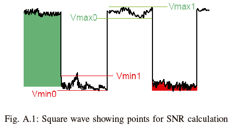
Since only the voltage is observable, it is converted to power by squaring and using a resistance of unity. Also, the noise acts as an erratic random wave and is essentially modeled as a sine wave to reduce complexity. From these points, equations for Pn and Psn are derived and are shown in (A.1) and (A.2), respectively, where the values for Vmin0, Vmax0, Vmin1and Vmax1are shown in Fig A.1.
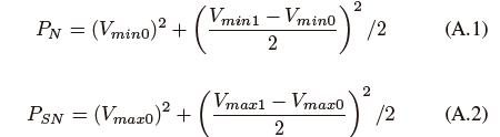
By subtracting (A.1) from (A.2) an equation for Ps is derived. Using Ps, an equation for SNR is calculated to be • The coefficient of ½ is due to the randomization of bits sent resulting in a 50% chance for a one and 50% chance for a zero being transmitted.
Line of Sight and Non-Line of Sight Theory
The Line of Sight (LOS) and Non-Line of Sight (NLOS) signals play a huge role in the transmission of data especially in a VLC system. Theoretical values of SNR may additionally be obtained by making use of (B.1) and (B.2) which describes the channel gain for both LOS and NLOS links respectively [33]. The received power can easily be obtained by multiplying this channel gain by the transmit power.

