


Serviços Personalizados
Artigo
 Inglês (pdf)
 Artigo em XML
 Referências do artigo
Indicadores

Links relacionados
-
 Citado por Google
 -
 Similares em Google
Compartilhar

 Permalink
SAIEE Africa Research Journal
versão On-line ISSN 1991-1696
versão impressa ISSN 0038-2221
SAIEE ARJ vol.114 no.3 Observatory, Johannesburg Set. 2023
Development of a self-contained robotic hand with dexterous grasping capabilities for research applications
Samantha Woods; Callen Fisher
Faculty of Electrical and Electronic Engineering, Stellenbosch University, South Africa, cfisher@sun.ac.za
ABSTRACT
Thumb loss can diminish one's hand's functionality by up to 40% and the loss of one's entire hand can severely impact a person's ability to perform simple day-to-day tasks. Therefore, there exists a need to focus on the development of a thumb mechanism which supports dexterous grasping activities in anthropomorphic robotic hands. This paper documents the design process of a novel robotic hand, and shows experimental results validating its overall performance. A large focus was placed on developing a novel thumb mechanism which could replicate the thumb's characteristic movement types, namely flexion-extension, abduction-adduction, and opposition-reposition. Additional focus was placed on developing a mechanism for flexion-extension movement of the fingers which did not incorporate passive components and on producing a fully self-contained prototype - with the electronics and actuators contained inside the palm, and the power supply inset against the back of the palm. The hand successfully followed motion commands from a sensor glove, and was able to replicate 14 grasp configurations which demonstrated its dexterous grasping abilities.
Index Terms: Robotic hand, Thumb mechanism, Grasping experiments
I. INTRODUCTION
The development of robotic hands has become increasingly prevalent in the past 30 years, with multiple applications across fields such as automation, medical robotics and prostheses [1], [2]. Hands for non-prosthetic applications typically consist of three digits mounted in a claw or pincer configuration, and do not mimic human hands. These hands are designed around task specific requirements and are not for general use. Given the ever-expanding role of robotics in our day-to-day lives, there is a need for a more general anthropomorphic hand capable of improved dexterity and control, with the ability to task-switch. These hands must balance power, dexterity and weight in order to be considered feasible [1], [3].
The human hand's complex and unique musculoskeletal composition makes it difficult to formulate a comprehensive kinematic profile for all the digits [4]. Instead, researchers find it easier to describe finger and thumb motion in terms of three characteristic movement types, which are detailed below and are shown in Fig. 1.
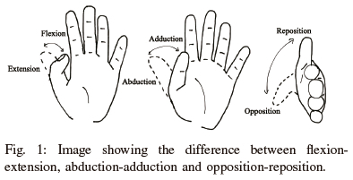
• Flexion-Extension (F-E): This describes the bending (flexion) and straightening (extension) of the fingers and the thumb [5].
• Abduction-Adduction (A-A): This describes the movement of the fingers and thumb toward (adduction) and away from (abduction) the midline of the hand [5].
• Opposition-Reposition (O-R): This describes the movement of the thumb across the palm, toward the pinky (opposition), and back to its resting position (reposition) [5].
Developing a fully actuated and functional set of fingers typically requires a complex mechanical design along with an equally complex control system in order to replicate the complex kinematic profile of the human fingers. Subsequently, most commercial prosthetic hands implement an under-actuated set of finger mechanisms, driving multiple joints with a single actuator and omit certain movement types [1]. One such movement type is finger abduction-adduction, which is considered less important for dexterous grasping than thumb abduction-adduction [1], [6].
Studies have shown that the majority of the human hand's prehensile grasping abilities arise from the evolution of the thumb opposition-reposition movement along with the ability of the palm to bend [4], [6], [7]. Thumb motion, in particular, assists with successful grasping and object manipulation [4]. According to [4], thumb loss can diminish the hand's functionality by up to 40%. Several early robotic end-effector designs have successfully replicated the region of motion of the human thumb, but few anthropomorphic hands have included a mechanism capable of successfully replicating the thumb's characteristic movement types - namely F-E, A-A, and O-R [4], [7].
Analysis of the thumb's musculoskeletal arrangement in [7], shows that it is difficult to isolate which parts of the thumb's structure are responsible for each type of movement. The same structure which allows for proficient object manipulation and grasp stabilisation is responsible for the difficulties in defining the thumb's kinematics [4]. Investigations of several prosthetic thumb mechanisms by [4] and [7] reveal that these mechanisms are under-developed, with many prototypes requiring manual adjustment by the user, or simply failing to include a mechanism for the opposition-reposition and abduction-adduction movement types which are vital for replicating the human hand's grasp space.
Although recent advances in 3D-printing technology have led to a surge in the development of low-cost, anthropomorphic robotic hands, these designs compromise on functionality and often hinder patients rather than assist them with day-to-day tasks [8]. Additionally, many of these low-cost designs incorporate tensioners, such as cables and/or springs. These components are associated with increased complexity and design shortfalls which compromise durability, grasp precision, and compactness [9], [10].
Tendon-driven mechanisms are popular for research applications because they allow for the actuators to be mounted remotely, unlike gear or linkage mechanisms whose actuators must be mounted inside the palm [11]. However, the complex relationship between actuator rotation and finger position makes precise control difficult, while cable elasticity and friction introduced by belt pre-tensioning means tendon systems are associated with lower efficiency and robustness than other mechanisms [9], [10], [12].
Linkage systems, on the other hand, are more complex to design and implement than tendon drives, but are associated with higher grasp forces, less friction at the joints, more robustness and durability, and higher operational accuracy [12], [13]. In [14] it is observed that linkage mechanisms require a lower applied force to achieve flexion-extension movement than tendon mechanisms and perform dexterous grasping with more accuracy.
Linkage mechanism designs vary greatly depending on the functional aims of the mechanism, with many linkage systems using one of two types of linkages, namely coupled four-bar (CFB) linkage and under-actuated four-bar (UFB) linkage [13]. CFB linkages are more compact and simpler to implement than UFB linkages and provide a flexion-extension path that mimics the natural grasping of the human hand [13].
This paper presents the development of a low-cost, 3D-printed robotic hand which can be controlled wirelessly and is intended as a research platform. Major focus is placed on developing a mechanism for replicating the complex movements of the thumb. Additional focus is placed on developing a mechanism for flexing and extending the fingers and thumb which does not incorporate tensioners, and on ensuring that all of the hand's electronics and actuators are contained within the palm.
This paper starts with the design methodology in Section II, followed by the interface mechanism for the hand, detailed in Section III. This is followed by a description of the different experiments performed and their results in Section IV. The paper concludes with a discussion in Section V and a description of future work in Section VI.
II. DESIGN METHODOLOGY
The robotic hand developed for this research was comprised of two focal points: the fingers and the thumb. In line with common practice [1], [6], the decision was made that the motion of the fingers was limited to flexion-extension motion, which was implemented using a linkage mechanism. To limit design complexity, the designed fingers were not capable of adaptive grasping.
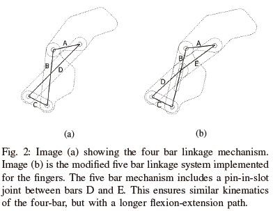
The design complexity was further limited by including what would anatomically be the medial and distal finger segments fused at a 35 degree offset. This reduced the complexity required of the mechanism for flexion-extension movement. Limiting the number of joints in this way also reduced the mechanical vulnerabilities of the mechanism without any major detriment to the grasping motion path of the finger. A four-bar mechanism, pictured in Fig. 2a, was adjusted intuitively until arriving at the five-bar mechanism visualised in Fig. 2b. The extra constraint created by implementing a pin-in-slot joint between bars D and E meant that this linkage exhibited similar kinematics to the four-bar linkage, but with a longer flexion-extension path.
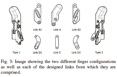
From there, the linkage mechanism was further adapted such that each finger could easily be attached to the palm and actuated by a single micro-servo motor (TowerPro MG92B) mounted inside the palm. Owing to the need to limit the size of the design relative to the proportions of a human hand, the decision was made to develop two different finger designs. Each design featured the same basic linkage, with corresponding links having matching lengths, but with different links acting as the driving link for each mechanism - link D for the first configuration and link B for the second. This allowed for the servo motors to be mounted in a stacked configuration inside the palm. While keeping to the overall form and size constraints assigned to the fingers, the lengths of the individual links were adjusted empirically using the Siemens NX11.0 software, such that the flexion-extension motion path was maximised. The final design of these fingers is shown in Fig. 3.
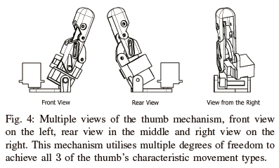
As stated in Section I, a simplified description of the thumb's complex kinematics can be given in terms of three characteristic movement types. Working according to this simplified description made it easier to visualise the movements of the thumb - as can be seen in Fig. 1 - but still presented a fairly complex design task. Tracking the thumb through several of the grasp configurations in [6] revealed that opposition-reposition movement could be described as a rotation through 90 degrees around a point in the base of the palm, with abduction-adduction movement effectively tilting the body of the thumb towards or away from the palm. The directions of this opposition-reposition rotation and abduction-adduction tilt were constant relative to one another but shifted relative to the palm. As such, an approximation of a pan-and-tilt mechanism was used to implement both of these movement types. It was observed that the thumb's flexion-extension movement path was very similar to that of the fingers. Given the decision to limit the finger mechanism to a two-segment design, the same five-bar mechanism developed for the fingers was implemented for thumb flexion-extension movement with only minor adaptation.
The designed thumb mechanism consisted of an opposition-reposition arm, an abduction-adduction socket, and a flexion-extension linkage, which were combined as pictured in Fig 4. The motor for opposition-reposition movement was mounted inside the palm and anchored the entire thumb mechanism to the rest of the hand. The motors for both abduction-adduction and flexion-extension movement were mounted inside the abduction-adduction socket, which was designed to sit partially inside the palm to allow for the thumb to adduct flush against the side of the palm.
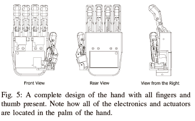
When designing the palm, the most important design consideration was how best to utilise the limited space. As mentioned previously, the flexion-extension mechanism for each of the fingers was driven directly by its own micro-servo. These all needed to be mounted inside the top of the palm in stacked sets of two. Motor mounts were required for each of these servos along with anchor points for the floating links of the respective fingers. The degree of symmetry that existed between the two finger designs meant that these anchor points were chosen to mirror the positioning of the micro-servos. Additionally, the lower half of the palm was designed such that it housed all of the hand's electronics, and a mounting point for the thumb's opposition-reposition servo motor. The virtual assembly of the completed hand design can be seen in Fig. 5.
III. ROBOTIC HAND INTERFACE AND ELECTRONICS
In order to test the functionality of the hand, it was wire-lessly connected to a glove which was worn by the operator. Both the hand and the glove were controlled using an ESP32 micro controller, and these two ESP32 modules were able to interface with one another by means of their on-board 2.4GHz wireless communication capabilities.
Along with its ESP32 micro controller, the glove consisted of a number of sensors (RP-L-170 Thin Film Pressure Sensor) used to detect flexion and an IMU (MPU9250) to determine the position of the thumb - by means of the TRIAD algorithm [15], [16]. The sensors in the glove were sampled at 10Hz. These measurements were converted to finger and thumb positions which were then transmitted to the robotic hand. The glove was powered by two 18650 batteries. It must be stressed that the sole purpose of the glove was to test the functionality of the hand, and is not a permanent solution.
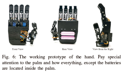
Along with its wireless interfacing functionalities, the robotic hand's embedded ESP32 module controlled the 4 servo motors used to actuate the fingers as well as the 3 servo motors which actuated the thumb, and was located inside the palm of the hand. The construction of the robotic hand can be seen in Fig. 6. As can be seen, the palm held the servo motors as well as all the electronics for the robotic hand. Only the batteries were located outside of the palm.
A number of algorithms were utilised in determining the positions to which each servo motor needed to be driven. First, on startup, the flex sensors on the glove were calibrated. This involved fully flexing and then extending the fingers to calculate the range of values received from the flex sensors. These maximum and minimum values were used to represent future flexion readings as a percentage of the total flexion range. These percentages were then transmitted to the robotic hand.
During the assembly of the hand, each servo was calibrated to operate within a specific minimum and maximum angle -determined using the NX11.0 software - needed to achieve full flexing and extending of each digit. Therefore, the percentage values received from the glove were converted to match a specific position within each servo's operating range, and communicated to said servos using a pulse width modulation signal.
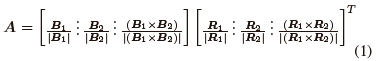
In order to determine the motion of the thumb, a TRIAD algorithm was implemented on the glove to calculate the position of the thumb relative to an inertial reference frame. Accelerometer and magnetometer readings from the IMU were used to populate two vector pairs - an inertial reference frame and a body frame respectively. Assuming the aforementioned vector pairs were not (anti) parallel, the rotation matrix A could be calculated, which rotated the vector in the inertial frame into the body frame [15], [16]. Due to the presence of noise, to improve the performance of the algorithm, the sensor measurements were normalized. This rotation matrix was calculated as follows:
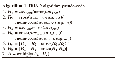
The algorithm took in four arrays, two of which contained the initial accelerometer and magnetometer readings, which were the inertial reference frame vectors, and then another two that contained the current accelerometer and magnetometer readings, which were the body reference frame vectors. This algorithm made use of the cross product function, cross(X, Y), the normalization function, norm(X), and the multiply function, multiply(X, Y) to produce a rotation matrix which represented the attitude of the thumb relative to the reference frame.
IV. EXPERIMENTATION
Due to the large variety of applications for which different robotic hands are developed, it is difficult to quantitatively test the performance of robotic hands and their control systems. Instead, the functioning of these systems is often assessed qualitatively, with success or failure being gauged by how well the system in question can replicate the characteristic movements and activities of a human hand.
In order to test the performance of the glove-hand interface, along with the attitude estimation for the thumb position, the glove was worn by the author who moved their thumb through a number of positions to see how well the robotic hand's thumb mechanism could replicate the human hand's characteristic thumb movements. The outcome of this test was assessed by visually comparing how well the robotic hand's thumb mimicked each position. An example of this as can be seen in Fig. 8. From these results, we could conclude that the thumb accurately tracked the motion of the human hand and thus the entire system was functioning correctly.
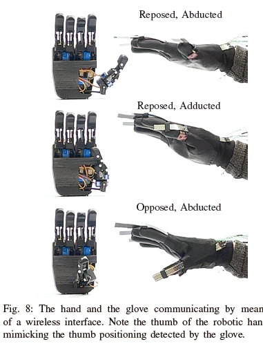
It must be noted that the real time performance of the thumb was not optimal, due to the limitations of the TRIAD algorithm. When the thumb was accelerating from one position to the next, it corrupted the gravity vector measurements, causing a breakdown of the TRIADs algorithm. However, slower tests resulted in optimal results. As previously stated, the glove and TRIAD algorithm were developed for the sole purpose of testing the robotic hand, and should by no means be considered a final solution.
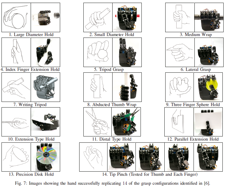
The grasping capabilities of the hand were assessed based on how well it was able to replicate 14 grasp configurations selected1from the GRASP taxonomy of human grasp types [6]. This was tested in two phases. First, the ability of the hand to replicate each configuration was confirmed using an NX11.0 assembly model to simulate each position. This was followed by a real-world test conducted using the built prototype hand. Fig. 7 presents a side-by-side comparison between the selected grasp configurations and those same poses as performed by the robotic hand.
All of the grasp configurations were replicated successfully in the simulation model, but difficulties arose during the real-world test for the writing tripod grasp. Repeated failures occurred as a result of slippage between the digits and the selected test artefact. This was not an altogether unexpected occurrence, as very little friction is introduced by the plastic surface of the fingers and thumb. Traction for grasping could easily be increased by adding a thin layer of silicone to the outer surfaces of link A for each digit.
V. DISCUSSION AND CONCLUSION
As seen in Section IV, the robotic hand developed during the course of this research can successfully interface with a control glove to allow for testing and design validation. The glove can successfully measure and transmit data relating to the motions of the human's fingers and thumb to the robotic hand. Once received, the hand is capable of interpreting this information and sending control signals to its actuators to mimic these motions. Testing revealed that the hand can successfully replicate all 14 of the grasp configurations selected from [6]. This demonstrates the efficacy of our novel finger and thumb mechanisms. The hand design is also successful in containing all of its actuators and electronics inside the palm, with the batteries on the outside of the hand but still inset against the back of the palm.
The TRIAD algorithm presented some problems when the motion of the thumb was rapidly moved. However, this is not necessarily a concern, as the TRIAD algorithm is implemented for this application purely because of its simplicity, allowing for straightforward testing of the robotic hand, which is the main purpose of the glove. Ideally, this problem could be solved by having two IMUs on the hand, one on the thumb, and one on the back of the hand. The acceleration motion of the hand can then be accounted for. The successful interfacing of the hand and the glove means that alternate methods of controlling the hand can be implemented, such as using EEG/EMG sensors.
VI. FUTURE WORK
Future work involves adapting the existing design of the robotic hand such that it will be suitable for use as an extremely low cost prosthesis for poorer regions. This will involve several adaptations: Primarily, the hand design must be made more compact. Secondly, the mechanical components must be manufactured using more durable materials, and the design must be adapted so that it is compliant with all the applicable safety standards, such as water and temperature resistance. Additional Engineering is also required to develop a mechanism for attaching the hand to a socket, as well as the development of the socket itself, so that the robotic hand can be comfortably attached to an amputee's residual limb. Finally, if the hand is to be used as a prosthesis, a more functional control mechanism must be developed.
VII. ACKNOWLEDGEMENTS
Special thanks go to Tommie Chambers at Siemens (Pty) Ltd, for organising access to the NX11.0 software as well as enrollment to the training course which allowed for its proper utilisation.
REFERENCES
[1] J. T. Belter, J. L. Segil, A. M. Dollar, and R. F. Weir, "Mechanical design and performance specifications of anthropomorphic prosthetic hands: A review," Journal of Rehabilitation Research and Development, vol. 50, no. 5, pp. 599-618, 2013.
[2] J. Falco, K. V. Wyk, and E. Messina, "Performance metrics and test methods for robotic hands," DRAFT NIST Special Publication 1227, 2018.
[3] A. V. Sureshbabu, G. Metta, and A. Parmiggiani, "A systematic approach to evaluating and benchmarking robotic hands-the FFP index," Robotics, vol. 8, no. 1, 2019.
[4] G. Cotugno, K. Althoefer, and T. Nanayakkara "The role of the thumb: Study of finger motion in grasping and reachability space in human and robotic hands," IEEE Transactions on Systems, Man, and Cybernetics: Systems, vol. 47, no. 7, pp. 1061-1070, 2016.
[5] O. Jones, "Anatomical terms of movement," Teach Me Anatomy, 30-May-2020. [Online]. Available: https://teachmeanatomy.info/the-basics/anatomical-terminology/terms-of-movement/ [Accessed: 17-Feb- 2022].
[6] T. Feix, J. Romero, H. B. Schmiedmayer, A. M. Dollar, and D. Kragic, "The grasp taxonomy of human grasp types," IEEE Transactions on Human-Machine Systems, vol. 46, no. 1, pp. 66-77, 2015.
[7] V. K. Nanayakkara, G. Cotugno, N. Vitzilaios, D. Venetsanos, T. Nanayakkara, and M. N. Sahinkaya, "The role of morphology of the thumb in anthropomorphic grasping: A review," Frontiers in Mechanical Engineering, vol. 3, 2017.
[8] G. K. Jones, and R. Stopforth, "Mechanical design and development of the touch hand ii prosthetic hand," RD J. South African Inst. Mech. Eng., vol. 32, pp. 23-34, 2016.
[9] E. Nazma and S. Mohd, "Tendon driven robotic hands: A review," International Journal ofMechanical Engineering and Robotics Research, vol. 1, no. 3, pp. 350-357, 2012.
[10] T. Zhang, X. Q. Wang, L. Jiang, X. Wu, W. Feng, D. Zhou, and H. Liu, "Biomechatronic design and control of an anthropomorphic artificial hand for prosthetic applications," Robotica, vol. 34, no. 10, pp. 2291-2308, 2016.
[11] V. N. Dubey and R. M. Crowder, "Grasping and control issues in adaptive end-effectors," International Design Engineering Technical Conferences and Computers and Information in Engineering Conference, vol. 46954, pp. 327-335, 2004.
[12] N. Omarkulov, K. Telegenov, M. Zeinullin, A. Begalinova, and A. Shintemirov, "Design and analysis of an underactuated anthropomorphic finger for upper limb prosthetics," 2015 37th Annual International Conference ofthe IEEE Engineering in Medicine and Biology Society (EMBC), IEEE, pp. 2474-2477, 2015.
[13] S. R. Kashef, S. Amini, and A. Akbarzadeh, "Robotic hand: A review on linkage-driven finger mechanisms of prosthetic hands and evaluation of the performance criteria," Mechanism and Machine Theory, vol. 145, 2020.
[14] F. J. Andres, A. Perez-Gonzalez, C. Rubert, J. Fuentes, and B. Sospedra, "Comparison of grasping performance of tendon and linkage transmission systems in an electricpowered low-cost hand prosthesis," Journal ofMechanisms and Robotics, vol. 11, no. 1, 2019.
[15] F. L. Markley, "Attitude determination using two vector measurements," 1998.
[16] S. Tanygin and M. Shuster, "The many triad algorithms," presented at the AAS/AIAA 17th Space Flight Mechanics Meeting, Sedona, Arizona, 2007.
1 The GRASP taxonomy categorises 33 grasps according to specific grasping properties. The 14 tested grasp configurations were selected as a subset of the total taxonomy which represented all 6 of the major categorisations.

Samantha Woods received her undergraduate degree in Electrical and Electronic Engineering in 2022 at Stellenbosch University. She is currently working for Siemens and is currently enrolled for a part time MEng degree at Stellenbosch University.

Callen Fisher received his PhD in the department of Electrical Engineering at the University of Cape Town in 2021. Dr. Fisher is now a senior lecturer at Stellenbosch University and is currently focused on legged robotics in extreme environments.

