


Services on Demand
Article
 English (pdf)
 Article in xml format
 Article references
Indicators

Related links
-
 Cited by Google
 -
 Similars in Google
Share

 Permalink
SAIEE Africa Research Journal
On-line version ISSN 1991-1696
Print version ISSN 0038-2221
SAIEE ARJ vol.113 n.2 Observatory, Johannesburg Jun. 2022
Applied Quasi-Distributed Fibre Bragg Grating Strain Sensors in Structural Damage Sensing of a Bridge Structure
P. BandaI; M. Delia TaminII; J. MeyerIII
IDepartment of Electrical and Electronics Engineering Sciences, University of Johannesburg, PO Box 524, Auckland Park, 2006, Johannesburg, South Africa (e-mail bpattricfajgmail.com)
IIDepartment of Electrical and Electronics Engineering Sciences University of Johannesburg, PO Box 524, Auckland Park, 2006, Johannesburg, South Africa (e-mail dellatamin@gmail.com)
IIIDepartment of Electrical and Electronics Engineering Sciences, University of Johannesburg, PO Box 524, Auckland Park, 2006, Johannesburg, South Africa (e-mail johanm@uj.ac.za). Senior Member, IEEE
ABSTRACT
Bridge structural decay is a prevalent problem around the world. Consequently, most structurally deficient bridges are characterized by unknown levels of damage, which impose high socio-economic risks to society. To address these concerns, this study is aimed at determining how to accurately sense the damage present in a bridge structure. Owing to the pitfalls of conventional sensing technologies and the complexities associated with civil structure instrumentation, the use of fibre optics sensors is found to be relevant for this study. While the employment of quasi distributed fibre Bragg grating strain sensors is not a relatively new concept, research is still necessary for their effective deployment in structural damage monitoring systems. A proof of concept for the developed sensing system is primarily simulated and thereafter demonstrated in the laboratory through a series of strain measurements tests conducted on a reinforced concrete slab. The experimental set-up consisted of a serial array of five wavelength division multiplexed fibre Bragg grating sensors, which were coupled with swept wavelength laser scanning technology. The experimental sensing resolution of less than 0.5 uεwas achieved. Structural damage information was extracted from the measured multipoint flexural strains, using our developed macro-modal strain ratio cross correlation algorithm. Alternatively, to simulate our sensor system response, vibration field tests, and finite element analysis were conducted on the Beatrice Bridge in Zimbabwe. Therefore, this paper presents the simulation and experimental results of a simulated and designed structural damage sensing system, based on quasi-distributed fibre Bragg grating strain sensors.
Index Terms: Fibre Bragg grating, macro modal strain ratio, quasi distributed sensors, structural damage
I. Introduction
Structural aging and deterioration of highway bridges are currendy an acknowledged worldwide problem [1], [2], Highway bridges are a critical integral component of the transportation network and there are vital for sustaining a nation's socio-economic system. Nevertheless, numerous bridges around the world are structurally deficient. In South Africa 94% of the bridges in Johannesburg were classified as structurally deficient [2] and some of them are considered dangerous [3]. The severity of damage presented in most of these structures remains unknown and its late detection presents severe negative implications for the society. Thus, to address these concerns, this study, is dedicated to the development of an optical fibre sensor, which accurately senses structural damage.
Optical fibre sensors (OFS) have great potential in monitoring physical parameters for measuring long-term structural behaviour such as creep, temperature effects, corrosion, fatigue, cracking, and other anomalies [4]. Motivated by the need to develop safer structures, numerous researchers have devoted attention to develop bridge integrity monitoring system based on OFS. The earliest important milestone for bridge instrumentation using the fibre Bragg grating (FBG) was demonstrated on the Beddington Trail Bridge in Canada in 1995 [4]. In preceding years, several structures were also instrumented using different OFS and these include the Dresden Bridge in Germany 1996, Tsing Ma Bridge in China 2003, Leizeira Bridge in Portugal 2007, Minneapolis Bridge I-35W in USA 2007, Kawane Bridge in Japan 2010, and Shenyang Boguan Bridge in China 2017 [5]. Reviewing the past literature, it can be noted that of all the OFS schemes, the quasi-distributed FBG sensing has been dominantly employed as a technique for bridge sensing. The popularity of this sensing approach is attributed to the exceptional sensing qualities of the FBG sensor, which are widely reported in literature [6]. Nevertheless, these sensors face inherent limitations and were criticized [7], for only sensing parameters at the point of their placement. Despite this limitation being acknowledged, it is not well researched. In addition, most literature studies concentrate on presenting the sensing capabilities of the FBG sensors only, and do not provide an effective methodology for extracting the damage information from the sensed parameters.
In this paper, the analytical modelling, simulation and experimental test of a structural damage sensing system based on fibre Bragg grating strain sensors are presented. The designed sensing system comprised of a serial array of five wavelength division multiplexed (WDM) FBG strain sensors, coupled to a swept wavelength laser scanning system. The strain measurand is collected on a reinforced concrete slab at the University of Johannesburg (UJ). To test the feasibility of the system, the system is simulated using the vibrational data collected from the Beatrice Bridge in Zimbabwe. Finite element analysis (FEM), reference sensor networks, and past literature were used to validate the findings. In this study, we practically demonstrate our improved macro modal strain ratio cross-correlation algorithm, in extracting damage from the multi-point strain measurand acquired using FBG sensor system. The algorithm maps and interpolates damage information from structure locations, which have not been instrumented by FBG sensors. The purpose of this study is to demonstrate the accurate sensing and effective extraction of a damage information using a quasi-distributed FBG sensor network.
II. Theory of Bragg gratings
A FBG is a waveguide, which consist of a spatial quasi-periodic modulation of the refractive index along the fibre length. Acting like a narrow wavelength filter, it has band pass in reflection and band pass in transmission. For simplicity, the FBG can be taken as a perturbation to the effective refractive index of the fibre core, which is expressed as:
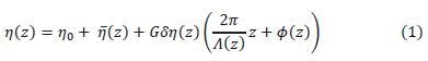
where N0 represents the unperturbed effective refractive index of the fibre and n (z) describes change of the average refractive index. A(z) is the grating's period at distance and z is a function of the period. δn(z) and Φ(z) are the grating apodisation and chirp respectively, whereas G represents the apodisation parameter. The grating planes create phase fronts that are perpendicular to the fibre's longitudinal axis. When light propagates in the optical fibre, it interacts with each grating plane of the FBG. At each consecutive index variation, a small amount of the light is reflected successively and adds coherently at determined wavelengths, called Bragg wavelengths. The first order resonant condition for this phenomenon is given by [4]:

where λB represents the Bragg grating wavelength. Only wavelengths, which are very near the λB are back reflected by the grating inside the fibre core. The Coupled mode theorem can be used to deduce the reflective power R(λ), which is the proportion of light at a given wavelength reflected by a uniform FBG and thereby expressed as [7]:
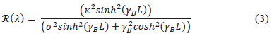
where λB =  L is the grating length. The dc and ac self-coupling coefficients are σ and k respectively. The Bragg grating resonance wavelength depends on effective refractive index of the core and the grating periodicity, according to (2). Therefore, any perturbation that changes those quantities induces a shift in the relative position of λB . By tracking this shift, the perturbation is determined and the FBG sensing phenomenon is established. However, the Bragg grating wavelength shift is cross sensitive to both strain and temperature [6], hence the deconvolution of these parameters is necessary in sensing applications where only one perturbation is of interest. Consequently, straining the fibre causes stress within its lattice in both transverse and longitudinal directions. The wavelength shift due to strain is given by [7]:
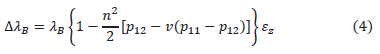
where ΔλB is the wavelength shift. ez is the applied strain along the fibre axis. p1l and p12 are the strain optic tensor components, and v is the Poisson's ratio. Strain is an indispensable structural integrity monitoring parameter as it accurately indicates the local structural response through direct measurement of the deformation intensity. Thus, the strain measurand is important for ascertaining structural damage. By definition, structural damage is considered to be the changes introduced to a system, which adversely affects its current or future performance [8]. Numerous damage identification philosophies presented in literature [9] assess structural characteristics, through modal analysis, dynamic flexibility measurements, matrix updating, wavelet transform, auto regression-basis, and natural frequency analysis.
III. Numerical modelling approach
This study is dedicated to the development of a fibre optic sensor system, which can accurately detect structural damage on a bridge. The basic arrangement of the optical sensing system is depicted in Fig. 1.
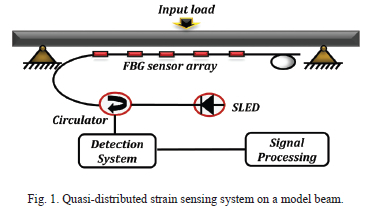
The system presented in Fig. 1 consists of a broadband source coupled to an optical circulator and then to a serial array of five WDM FBG sensors. The purpose of the quasi-distributed sensors is to sense multipoint static and dynamic strain measurand on a loaded structure. The model represents a typical RC beam found in bridges. The beam is a major load bearing component and carries loads applied perpendicularly to its longitudinal axis. Hence, it was targeted for integrity instrumentation To aid analysis, the mechanical set is assumed to be structurally damaged having a crack at the vicinity of sensor 4. Assuming, that FBG sensors measuring both strains and temperature are attached on the bottom surface of the beam, the optical system response is presented in (6):
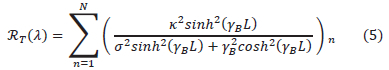
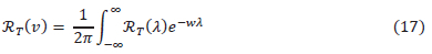
where RT(λ) is the reflection spectrum from the nth local sensor and is the number of local sensors. When the quasi-distributed N sensor network does not have external perturbations, the optical signal becomes a superposition of all the reflected spectrums written as [10]:
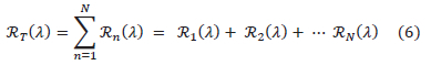
where RT(λ) is the optical signal that is detected by the interrogator. R1(λ), R2(λ) and RN(λ) represents the reflective spectrums of all the FBG sensors in the channel. When the quasi-distributed sensor network has external perturbations, the gratings elongate and the spectrums shift in response to the measurand is theoretically represented as:
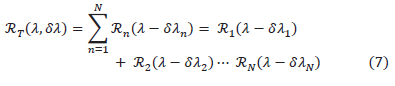
where RT(λ,δλ) is the optical signal due to external perturbations and δλn is the Bragg wavelength shift. Sensor optimisation is necessary as the number of sensors on a channel is limited by the source bandwidth, the FBG sensing bandwidth and the interrogator speed. In the WDM configuration, each sensor has a distinct operation range and overlapping is not acceptable.
A. Mechanical structure considerations
The static and dynamic strain response of the structure can be determined using structural mechanics principles. By analyzing the structural response of the instrumented beam, the local strain measurand active on each sensor can be predicted. For this purpose, we employ the Euler-Bernoulli beam theorem, which is widely applied in practical structure analysis [11]. The description of the behaviour of a beam subjected to a time-variant transverse load f(x, t), is defined as [12]:
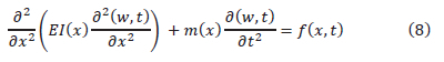
where d2(w, t)/dx2 is the second derivative of transverse deflection E,l(x), and m(x) are the Young modulus of elasticity, moment of inertia and mass respectively. Assuming that the simplified structure is uniform with constant parameters, the solution of the differential equation is W(x, t) being separable in the spatial variable x and time t being expressed as [12]:

where w(x) is the shape profile function and F(t) represent the profile's amplitude time variation. Using, the Euler-Bernoulli theorem, the shape profile and bending strain of the deformed beam can be determined. This is based on the concept that the internal energy of a beam is predominantly due to flexural stress and strain. The strain e(x) and transverse deflection w(x) of a loaded beam have the well-known relation:
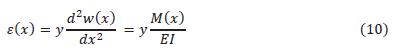
where y is the vertical deflection of the centroid axis of the beam and M(x) is the bending moment relationship [11]. El is the beam stiffness and it determines the load bearing capacity of a structure. It is constant, along the axis of an undamaged uniform beam and anomalies indicate possible damage.
B. Mode shape and strain analysis
The main purpose of setting up a numerical model of the distributed sensing systems is to simulate measurements of strains, which are continuously monitored in bridges. As the strain distribution along the beam is of primary interest, theoretical strain mode shapes of different vibration modes of the beam are analysed through examining (9). From (9), we realize that the strain of the beam is proportional to the second derivative of that transverse deflection. The deflection in the beam can therefore be described as [13]:
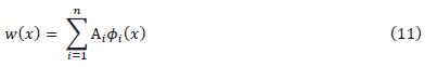
where Ai is the excitation force that is dependant on vibration amplitude at mode i, and Φi is the ith modal displacement mode shape. Assuming a simple supported structure, the displacement mode shape is [9]:

where at = (sinhyiL - sinyiL)/(coshyiL - cosyiL) and for the first three modes, yiL = 4.73,7.85 and 10.99 (i = 1,2 and 3) [14].
Considering the lowest structural resonances only, the transverse displacement equation becomes:

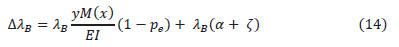
where wi is the transverse displacement at mode i. Therefore, the strain mode shape is considered to be (15): Therefore, the strain distribution response along the beam axis can be sensed. The associated Bragg wavelength shift on an FBG sensor in the network is calculated using (6) and (11). It is presented as:
where pe is the strain optic coefficient. Effective determination of the response of each FBG strain sensor on the structure is conducted using modal analysis. From the mechanics perspective, the purpose of conducting modal analysis is to determine the dynamic properties (mode shapes and natural frequencies) of a structure under vibrational excitation. In general, modal analysis is performed through solving and analysing the Euler-Bernoulli beam equation under boundary conditions. For a continuous simply supported beam the simple solution form of the deflection modes is:

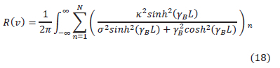
where Yk (x) is the deflection mode, I is the beam length and n is the mode number (where n = 1,2--). Subsequently, the beam's natural frequency is presented as [12]:
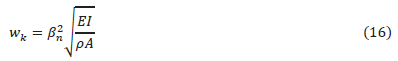
where wk is angular frequency at a deflection mode. β2n is a constant which depends on the boundary conditions, p is the density and A is the cross-sectional area. In Section V, we apply these mode shapes and natural frequencies relations (18) to simulate the response of the FBG sensor network, attached on a structure, which is subjected to external excitation.
IV. Damage identification and analysis
In this study, the detection, localization and analysis of damage was achieved using two main steps: i) Demodulation of the measured FBG sensor signals from wavelength domain to strain, ii) Signal processing of the strain signal using an algorithm to extract damage information. These steps are presented in the following subsections.
A. Strain demodulation principle
To evaluate the static and dynamic strain changes in the local sensor domain, we employed the Fast Phase Correlation (FPC) demodulation algorithm. The FPC has the capability of measuring rapidly and accurately the Bragg shifts of strain sensors under noisy dynamic loading [18]. It has proven success in literature [10]. The algorithm is based on the application of the fast Fourier transform on to the reflective spectrum of the FBG sensors as:
where RT(V) represents the reflective spectrum in frequency domain. RT(v) is the reflective spectrum in wavelength domain. Substituting (6) into (23), the spectra R(v) can be presented as:
where R(v) is the FFT of the resulting spectrum, which is the superposition of a set of triangle functions [10]. The FFT of (3) results in a triangle function as proved by [19]. A shift in the Bragg wavelength peak, due to a strain perturbation induces a change in the phase in the Fourier domain that can be tracked. In general, the strain demodulation principle consists of the calibration and measurement processes which include signal acquisition, filtering, separation of frequency components, comparison of the phase between spectrums, calculation of the median, and determination of the Bragg shift [20-21],
B. Damage detection and localisation methodology
Damage information was extracted from the multi-point FBG strain signal sensor, using our developed macro-modal strain ratio cross correlation algorithm (MMSRCC). Before, detailing the working principles of the MMSRCC, we elucidate its underlying background principles in the following sections.
1) Modal-macro strain ratio (MMSR) algorithm The MMSR algorithm is useful for extracting damage information from multiple point strain data acquired with FBG sensors. Several researchers in literature [9], [15] proposed its use as a damage extraction algorithm. However, there are limited reports on the practical application of the MMSR algorithm on real civil structures. The algorithm is based on the principle that under certain loading configurations, the ratio of strains measured at two different locations (from a selected reference) along a beam is constant [5]. Hence, for two given FBG sensor points along a beam denoted by x1 and x2, the theoretical strain ratio (SR) between a damaged section and the undamaged reference section at the vibrational mode i is [9]:
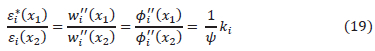
where εi*(xi) and ei(x2) are respectively the strains measured at a distance x1 and x2 from the same reference, ei*(x1) is the strain measurand at a damage location, w-i (x1) and wi- (x2) are
the transverse displacement respectively. and Φ(x2) are the transverse displacement mode shape respectively, ψ is the ratio of the effective flexural rigidities at damaged and intact conditions, ψ is unity for an undamaged state and ranges 0 <, Ψ ;> 1. ki is a constant whose value depends on the location of the measurements. According to (11), the strain vector is inversely proportional to the local stiffness constant of the instrumented beam. Thus, kt relates to the stiffness constant and indicates the physical soundness of a beam. Local damage in a uniform beam results in the reduction of the stiffness at the vicinity of the damage. This phenomenon can be detected through identifying the anomalies in the strain ratio at a given resonant mode. The MMSR algorithm is self-referencing and does not require a baseline for an undamaged state. Nevertheless, their application weaknesses include restrictions in load configurations and susceptibility to strain transfer errors.
2) Modal-macro frequency response algorithm The MMFR algorithm can be used to retrieve damage information from the dynamic strain measurand acquired using quasi-distributed FBG sensor. The MMFR can process dynamic strain data and is well suited for practical vibration tests. This algorithm relies on modal frequencies rather than modal strains. Many variant forms of this algorithm exist in literature [21]. It is based on the generic principle that under dynamic loading, the MMFR at any spatial location on healthy structure is the same. This implies that, the strain frequency signals from two separate quasi-distributed FBG sensors on the same beam structure would be equal. We describe this phenomenon by the relation:
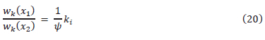
where. ki relates to the stiffness constant wk (x1) and wk (x2) are the modal frequencies at distances x1 and x2.
3) Cross correlation algorithm
In general, correlation can be described to be a measure of similarity between two signals. In literature [23], presented a variant Pearson cross correlation algorithm, as a useful analysis technique of extracting damage signature from the strain signal from FBG sensors. To detect structural damage, their technique relied on the principle of comparing the similarity in behavior of a measured strain signal to a baseline strain signal. A higher positive correlation indicates similar linear behaviour and a lower negative correlation infers dissimilar behaviour between signals. Though, their algorithm provides useful damage indices, it has an inherent weakness. The prerequisite requirement of a baseline signal of the undamaged state limits its practical use.
4) Modal-macro strain ratio cross correlation algorithm (MMSRCC)
Our developed damage detection algorithm is a modification of the two separate algorithms (MMSR and CC). The basis for developing this algorithm is to ensure effective feature extraction and pattern recognition, while optimizing on the strengths of both the MMSR and CC. The macro-modal strain ratio cross correlation algorithm is a two-step analysis technique, which uses the measured modal strain ratios to map and predict the strain field pattern for an undamaged state of the structure. The initial step is the computation of the ratio of effective flexural rigidities xp at damaged and intact states of the structure. The ratio of the effective flexural rigidities at a specific point can be deduced using the previously presented relation in equation (19). Thus, the effective flexural rigidity ratio at the point will be given by:
where vl and yt are the strain measurand collected from two FBG sensors at a specific distance from the same reference location. As previously elucidated ki is the parameter which relates to the stiffness constant of structure at that location. Predicting the idealised strain distribution trend is then possible since the stiffness constant of a healthy structure must effectively be constant. The next step of the algorithm is to compare and analyse the linearity in the strain-distributed trends acquired from FBG sensors. Hence, the correlation behaviour Pi, of the strain measurand trends is assessed using the relation:
where vi and yi are the strain measurand from two FBG sensors and the strain trend means are  .n is the number of time observations. Damage indices ζ values of the MMSRCC algorithm are generated through computing the dot product of the ratio of the effective flexural rigidities and strain sensor correlational data. We present the relation as:
To illustrate the MMSRCC algorithm, we simulate using Matiab and present the damage index definitions in Fig. 2.
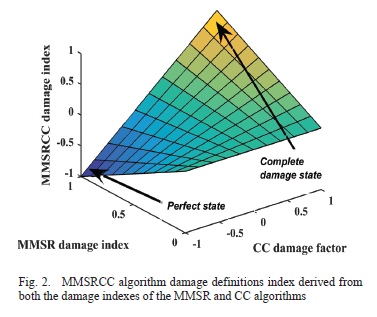
From Fig. 2. we can observe that the damage index definitions of the MMSRCC algorithm spans as a dot product of the vectors -1 to 1 and 0 to 1. The wider damage index definitions are more accurate and take into account the stiffness changes as well as the linearity of strain trends acquired from multiple FBG sensors. These relations can be used to verify sensor performance during damage extraction.
V. Sensing system simulation
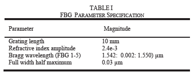
Having presented the fundamental modelling theory and the detection algorithm, we simulate the response of the designed quasi-distributed sensing system under constant thermal conditions. Both static and dynamic loading were tested. For the static test, a point transverse load of 530 N placed on top of the structure as illustrated in Fig. 1 was considered. The optical parameter specifications are presented in Table 1.
A. System response to static strain
The initial objective was to simulate the possible flexural mode shapes of the model beam when a static load is placed. The model beam dimension were 10 000 mm long, 350 mm deep and 300 mm wide. The instrumented beam deflection modes depicted in Fig. 3. were simulated using Matlab as a tool. The data in Table 2 and the response relationship given by (17) were used in the simulation process.
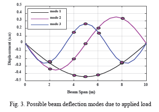
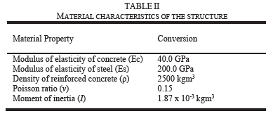
Fig. 3 presents the possible flexural mode shapes (mode 1-3) of the model, which are the respective deflection mode shapes the beam undergoes when subjected to transverse loading. The relative FBG sensor positions due to the modal displacements are indicated. The simulation results were limited to the three lowest resonance mode shapes as there are practically relevant. Thus, the flexural strain distribution response of the quasi-distributed FBG sensors under deflection mode shape 1 can be generated. The realised distributed strain response across the model beam axis is illustrated in Fig. 4.
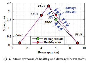
Fig. 4 presents the simulated distributed static strain response trends of the instrumented beam. The trends identify both the flexural behaviour of a healthy uniform beam and a damaged uniform beam. The response trends are generated using the local strain measurand on each FBG sensor on the network. A maximum strain of 0.24 μm is realised on FBG 3 sensor. Existences of damage on a beam lead to abrupt changes and non-uniformity in local strain measurand in the damaged region. The loss of stiffness of the structure was optimum on the damage location and recedes as distance increases from the damaged region. The corresponding Bragg wavelength shifts of each FBG sensor were simulated and are illustrated in Fig. 5.
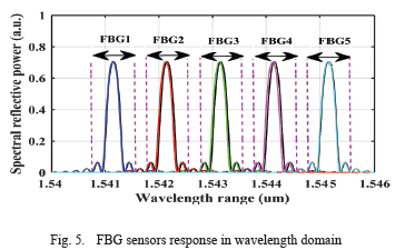
Fig. 5 presents the simulated Bragg wavelength shift of the attached gratings when static load is applied. The main assumption used in the simulation implied a maximum strain transfer from the beam to the attached gratings. As anticipated, the Bragg wavelength shifts of the loaded sensors were different and the maximum shift demodulated was 0.31 pm. Practical measurements of such small wavelength shifts requires the use of a high-resolute interrogator. The macro stain measurand are highly sensitive to damage [17].
B. System response to dynamic strain
In real bridge structures, the dynamic strain excitation is usually acquired from ambient sources such as traffic loading. In this section, we simulate the response of the quasi-distributed sensing under vibrational loading. In literature, the Lamberti's dynamic strain function is used to simulate vibration for practical situations and it is presented as [18]:
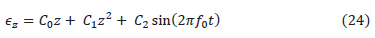
where C0,C1, and C2 are constants. To account for the dynamic and non-uniform nature of strain, C2 sin(27r/0t) introduces sinusoidal spectral shifting, C0z + C1z2 produces spectral distortion. The sensing system response to dynamic strain can be generated using (11), (16), and (22). Fig. 6 illustrates the predicted Bragg wavelength shift response of the sensors.
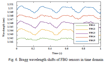
Fig. 6 identifies the Bragg wavelength shift response of each quasi-distributed sensor. Variances in the amplitudes of the Bragg wavelengths signals of the individual gratings are observed and there are attributed to the differences in the sensor spatial locations. Notably, there is no decay in the amplitude of the simulated wavelength signals with time, since an idealised structure was used. The wavelength shift responses of all the sensors in the network closely resemble the applied dynamic strain stimulus with high accuracy. This is expected, since, under thermal invariant conditions the Bragg wavelength shift is linearly proportional to the applied strain without hysteresis. Nevertheless, the time domain signal of these sensors do not fully reveal the damage information of the structure. For this purpose, a fast Fourier transform (FFT) is employed to process the time domain data. Fig. 7 presents the resulting Bragg wavelength shifts in frequency domain.
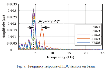
Fig. 7 identifies the frequency response of all the FBG sensors on the network. Notably, all sensors have the same frequency except for a frequency shift exhibited by sensor 4, which is near the cracked location. According to (18), the change in the modal frequency indicates loss of beam stiffness and shows possible damage. The presence of damage on the model cracked beam was had been modelled by assuming a 4% reduction of the beam stiffness. The assumption is not novel, as it was used in literature cases. Calculation of the vibration frequency of the beam at the sensor placement location had been conducted using the relation presented in (16). The strain transferred to the FBG sensors was modelled using the relation presented in (24) and the frequency deduced using the relation (16). It is evident, through computation the relation in (16), that a 4% reduction in the beam stiffness correspondingly results in just a 2% change in the structures resonance frequency of vibration. Damage detection through the measurement of frequency changes, is widely accepted in literature to be challenging due to the realized low frequency changes [9]. However, FBG sensors can adequately sense these small changes when coupled to an interrogator with high sampling frequency and high resolution. Furthermore, a quasi-distributed sensing system is self-referencing in case of modal frequencies due to temperatures.
VI. Laboratory experimental work
A. Grating Inscription
FBGs were inscribed in a step index photosensitive single mode fibre (SMF) using phase mask technique. A frequency doubled continuous wave Argon ion laser at 244 nm (100 mW) was used to irradiate photosensitive fibre through the phase mask. The grating inscription setup consisted of a laser source, a three-directional translation stage, a super luminescent emitting diode (SLED), photosensitive SMF and a detection system. The grating was written at a uniform scanning speed of 0.37 mm/sec having length of 10 mm. The resolution of the optical spectrum analyzer (OSA) was set to 0.1 nm, 3 dB, and a wavelength range of 20 nm span. The phase mask set at 0-degree tilt angle, creates a near field interference pattern, which is transferred on to the fibre. The cleaved SMF is placed on a 3 dimensional translation stage at the interference of the two beams. Silicon coating was used to protect the bare gratings. The SLED illuminates light inside the SMF and the OSA was used as the detection system to monitor the grating's reflectivity and characteristics during the inscription process.
B. Experimental strain measurement tests: RC slab at University of Johannesburg (U.J)
After the gratings were printed, static and dynamic strain sensing tests were conducted on the RC slab at U.J. The objective of the tests were to study the performance of FBG sensors in quantifying strains. The sectional view of the test structure and the optical setup used is presented in Fig. 8. The optical schematic comprises of a serial array of FBG sensors coupled to a continuous swept laser-scanning source. Light from the optical source (Bragg Monitor HBM FS22) is illuminated into an array of WDM FBG strain sensors depicted in Fig. 8.
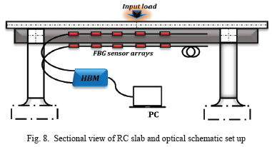
In addition, Fig. 8 depicts the mechanical structure of the test structure used in our laboratory experiment. The RC slab at UJ was used as the test structure. It is made of a two-way slab, weighing 910 000 N. Fig. 9 presents the pictorial view of the RC slab used for laboratory tests. It has structural characteristics, which are similar to typical slabs of beam and pier bridges.
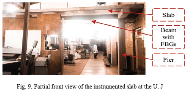
Fig. 9 depicts the partial front view of the RC slab. In the tests, attention was limited to studying the flexural strains on the main load-bearing beam of the slab. The selected reinforced concrete beam was 9620 mm long. 350 mm deep and 300 mm wide. The beam was also instmmented with embedded FBG sensor, which served as good reference. For the static tests, the structure was loaded by placing a static invariant load of 530 N on top of the slab. Dynamic loading was accomplished through specific jumps made by one subject on top of the slab. In literature, this simple dynamic excitation technique was successfully used when vibrational shaker systems were absent [20]. To quantify the structure's response due excitation, we used the Bragg Monitor interrogation system presented in Fig. 10, to measure the Bragg shifts of the FBG sensor array.
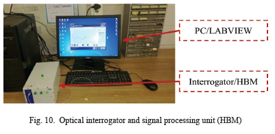
The optical interrogator presented in Fig. 10 is connected to a laptop equipped with dedicated software. The optical sensing interrogator comprises of a scanning swept laser wavelength source and four optical channel outputs. The Bragg Monitor interrogator directly encodes the measured response as vector arrays of Bragg shift of the sensors at each step. To successfully resolve the reflected spectrums. each sensor was sufficiently separated with a 4 pm wavelength window from each other and placed in critical spatial locations at the bottom part of the beam where damages were anticipated. The FBG sensors had distinct Bragg wavelengths with a narrowband reflection spectrum. The system measurement the optical range is 1500-1600 run. The sensing system provided high signal power through all the sensors on the array. The optical source had a narrow spectral line width. The sensing system resolution was less than 0.5 μe.
C. FEM Validation of the RC slab strain sensing tests
To validate the accuracy of the static and dynamic strain sensing experimentation process, finite element analysis was conducted for the two-way RC slab at UJ. The finite element modelling is a numerical technique, which is employed in analyzing structural shapes using predefined materials specifications. The basic concept behind FEM is to discretize the solution domain into subdomains called finite elements connected by nodes. The stress, deformation and displacement characteristics are then analysed for each element. As such, a three-dimensional model of the reinforced concrete slab was developed to demonstrate the accuracy of the sensing method. Solidworks software was used as a tool for this analysis. Material property determination is important when employing the FEM technique. The assigned material properties used for the modelling were presented in Table 2. Mild steel was not explicitly modelled and instead concrete was assumed to be uniformly distributed throughout the sections by artificially adjusting the modulus of elasticity of the concrete. This assumption has been successfully in practical cases, without much loss of accuracy. Fig. 11 presents the slab structure model. The slab model restraints and the load application area are illustrated in the Figure 11.
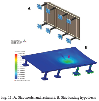
Fig. 11 presents the boundary conditions on the base of the slab. To ensure results accuracy, discretization of the model was done using a fine solid tetrahedral standard mesh of high quality. The characteristic element size was 0.228m, the number of elements in the simulation was 35936 and the total nodes were 67275 and 4 Jacobian points in the simulation. A static load of magnitude 530 N was used in the static simulation test.
VII. Field experimental work
A. Beatrice Bridge vibration sensing test
In parallel with the laboratory experimentation, a series of field-tests where undertaken at a local bridge site. The Beatrice highway bridge was selected as a candidate for field experimentation. The bridge has unique structural characteristics and perceptible vibrational behaviour. The Beatrice Bridge has a total length of 70 m, consisting of two spans of length 24.0 m and an overhanging middle slab of length 6.7 m. Part of the pictorial view of the bridge is presented in Fig. 12.
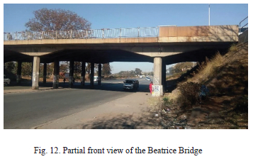
Depicted in Fig. 12, the Beatrice Bridge is structurally composed of deck-on-beam and pier system and cast in-situ reinforced concrete elements. Knowledge of the dynamic characteristics of a structure is important. Practical fibre optic instrumentation of the Beatrice Bridge was not possible due to resource limitations. The structure had to remain operational at all times and the optical interrogator was far from bridge site. To overcome these limitations, we employed ambient vibrational tests and our sensing process took place on the top of the superstructure on locations of negative flexural moment. Alternatively, we used an ADXL 345 vibration sensor serially connected to an Arduino Uno data acquisition system (DAQ), to acquire the vibration signature of the structure. In literature, several studies have also been conducted successfully in acquiring the vibration signature of bridges using an Arduino Uno DAQ [21]. The test procedure started with installing the accelerometer at a sensor location for the current setup and it was then moved from setup to setup in order to cover all sensor locations to acquire the relevant data. The structure response due to ambient traffic excitation was measured. The obtained response was characteristic of the true operating conditions of the structure, typically known as operational or output-only modal analysis. The sensors have the capability to measure the three dimensional vibration and the frequency range was 0-100 Hz. The ADXL 345 vibration sensor and Arduino Uno works through a PC with LabVIEW interface. By measuring the vibrational behavior, which was used to ascertain the bridge's natural frequency.
B. FEM validation of Beatrice Bridge experimentation
To study the behavior of the stress-strain distributions on the Beatrice Bridge, a 3-dimensional, linear elastic global model using Solidworks software was developed. The piers of the RC bridge were modelled and restrain at the base, to approximate the physical constraints on the real bridge. The structure was discretized into smaller finite elements using a solid tetrahedral mesh. The characteristic element size in the fine mesh was 823 mm and 41227 solid elements were connected using 73849 nodes. This choice of solid elements represents the mass distribution and stiffness within the structure with high accuracy the response of the bridge due to static loading is analysed. For the load hypothesis, a stationery truckload (560 kN) at the mid span of the bridge was considered. The load placement location was estimated using influence lines for a beam. A number of 10 nodes were selected as the candidates of sensor locations. The bridge displacement due to the loading, and the FEM predicted strain responses at the girders beneath the bridge are illustrated in Fig. 13. The figure also illustrates an enlarged view of the Solidworks predicted flexural strain distribution response on the lower girders of the bridge.
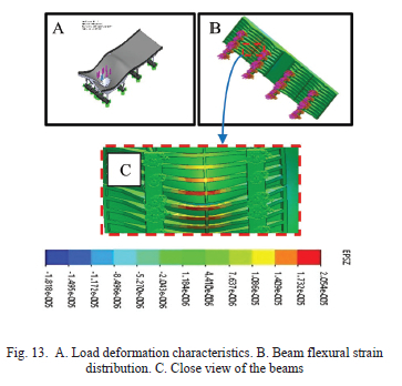
Observing Fig. 13 the maximum simulated bending strain was 20.5 με at nodal locations near the beam mid span. Analytical calculation of the strain at the same nodal point using the flexural formulae yields maximum strain of 22.0 με. The analytical calculated value was only slightly higher, hence it validates the FEM result. The FEM predicted maximum strain results in a Bragg wavelength shift of approximately 20 pm on the local FBG sensor. Therefore, the FBG sensors can effectively measure the strain parameters on the bridge components. Our FEM are realistic, as they fall in the range of practical literature studies. [22],
VIII. Results and discussion
A. RC slab static test results: system response
The reflectivity response of quasi-distributed FBG sensors on the slab was analysed. Fig. 14 presents the FBG sensor characteristics and response to the applied static strain. All of the inscribed gratings were of low reflectivity with the highest reflectivity being - 17 dBmW. The variation in the reflective power of the gratings was possibly attributed to fluctuations in laser power, vibrations on the nanometer scale, and exposure time differences. The lowest signal to noise level was - 68 dBmW, hence each grating could be distinguished from the noise.
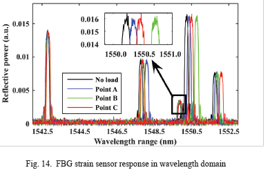
To test the sensing system performance, a transverse point load of 530 N was applied on the slab, directly above the instrumented beam. Fig. 15 illustrates the resulting strain trend. To validate the accuracy of the sensing system, the response from the attached FBG sensor network was compared to a reference sensor network of embedded quasi-distributed sensors.
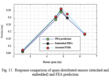
Fig. 15 presents the strain responses generated from the attached FBGs. The sensors from the two separate networks were not at the same exact positions, but there was close resemblance and good agreement in the trends. The maximum strain measurand from the attached and embedded sensors networks were 0.367 μεand 0.361 με respectively, resulting in a low percentage error value of 1.6%. The findings agree well with beam flexural trends found in [11]. The largest shift was observed on FBG 3,
which was centrally spatially located. The attached sensing system was highly sensitive as there was rapid shift of the strain peak when the loading was changed. The accuracy of the obtained experimental strain readings were also verified using FEM analysis of the RC slab. Fig. 16 shows the strain response of the model of the slab as a result of a 530 N concentrated load applied on it.
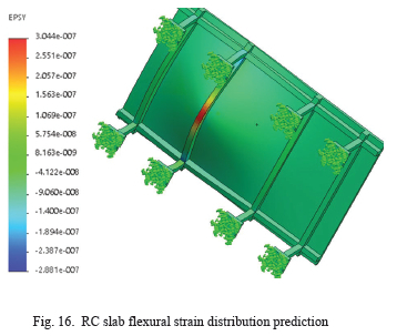
Fig. 16 highlights the simulated strain distribution along the axis of the model beam. Nodal positions were used to identify the FBG sensor positions. Solidworks predicted a maximum strain value of 0.344 ue at the mid span of the selected beam. Comparing the maximum strain value from the attached FBG sensing system and the FEM value at the same nodal location, we obtained a low percentage error value of 6.27%.
B. RC slab dynamic test: system response
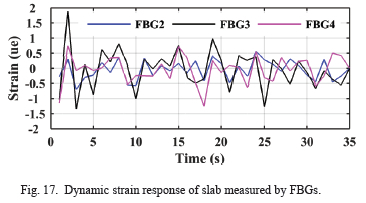
In the second laboratory experiment, dynamic strain measurement tests were conducted on the RC slab. Fig. 17 illustrates strain response from three FBG sensors when dynamic periodic load (530 N) was applied on top of the slab. Fig. 17 indicates the dynamic strain response of three attached sensors. Notably, significant maximum dynamic strain values were registered by FBG 3. Sensors FBG 2 and FBG 4 had lower strain values and appreciable time delay. The anomalies were attributed to the differences in sensor spatial location and structural damping effects. Unfortunately, our interrogator had a low sampling frequency (1 Hz) and hence it could only faithfully reproduce dynamic strain signal with frequencies less than 0.5 Hz. This frequency was relatively low for the application, since typical natural frequency of vibration of most bridge structures ranges from 2-8 Hz. Hence, the time domain dynamic strain data could not be processed into frequency domain strain data, due to possible information loss caused by the aliasing effect, according to the Shannon Nyquist sampling theorem [19].
C. RC slab damage assessment results
Structural damage on the slab was evaluated through analyzing the static strain data using the MMSRCC algorithm. Based on the principles elucidated in Section IV, the strain ratio values were used to predict and map the strain distribution response of the healthy response of the horizontal girder span. A strain distribution response was also generated using strains parameters measured on the RC slab. The two strain distributed sensors are presented in Fig. 18.
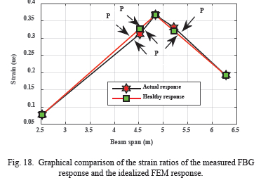
Fig. 18 illustrates graphically the comparison of the strain response of an idealized beam (without damage) to the measured strain responses of the FBG sensor instrumented beam. Slight anomalies in the strain distribution trend are observed at span locations 4.84 m and 5.22 m (points marked P). The percentage error of the sensor on these points (comparing the ideal MMSRCC and measured MMSRCC damage index) were 2.04% and 2.47 % respectively. According to the experimental results, damage can be detected even though the damage does not coincide with the sensor location, as the stiffness deterioration is transferred to adjacent elements. Similar results have been found in literature [21]. An important deduction, from the analysis is that the presence of damage does not only affects the local point but also the immediate neighbouring points. Therefore, if the quasi-distributed sensor placement is optimized, strain measurand from the nearest FBG sensors can be used to predict damage on regions on the structure, where there are no sensors. The phenomena thus becomes a constrained optimization problem. The acquired strain distribution trend can be used to map damage in structure locations, which are not instrumented. Interpolation and constrained optimization techniques can be utilized. The nearly constant macro-strain ratio low stiffness deviation indicate that the newly constructed RC slab at the UJ has not yet accumulated significant damage.
IX. Field results: Bridge vibration sensing
In this section, we present the results of the field tests conducted on the Beatrice Bridge. The bridge could not practically be instrumented due to resource limitations. Hence, to test the feasibility of our sensing system, we collected the vibrational signature of the bridge using vibration sensor. The sensor system was simulated on the system response using the practically measured vibrational signal as input. The practical vibration signal data acquired were overwhelming in quantity. Therefore, we present the results of the bridge vibration when a single truck passed over. Fig. 19 illustrates the simulated response of the sensing system in time domain on a 30 s window.
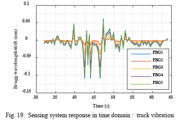
Fig. 19 highlights the Bragg wavelength amplitude variations of the quasi-distributed sensors. The variations are attributed to the differences in sensor spatial location and structural damping effects. An FFT algorithm was used to ascertain the structural characteristics and the resulting frequency response is illustrated in Fig. 20.
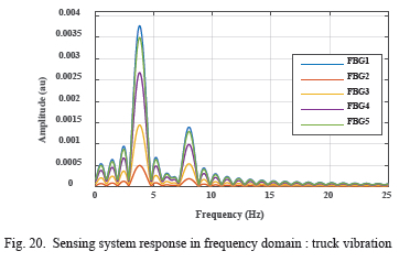
Fig. 20 identifies the frequency response of each individual FBG sensor on the network. The signal was filtered, segmented and then averaged to obtain the natural frequencies of the structure. Two distinct frequency patterns of 3.8 Hz and 7.9 Hz were observed and are indicated in Fig. 20. The natural frequency of the bridge vibration signal could be evaluated for structural damage. The obtained natural frequencies of the bridge vibration signal could be evaluated for structural damage using the earlier presented methodologies.
X. Discussion and conclusion
Bridge structural decay is of serious problem for transportation safety. Developing a structural damage sensing system-using fibre, Bragg grating strain sensors is critical to predict structural decay. Nevertheless being discrete sensors, with specific predetermined placement locations, FBG sensors have been criticized for failing to locate structural fault at points, which are not instrumented. Therefore, in our study, we presented the modelling, simulation and experimental validation of a designed WDM quasi-distributed FBG sensing system. The sensing system could accurately measure multi-point flexural strain measurand, with a resolution of less than 0.5 με.
Since, structural damage is evidenced as localized modification on the stiffness configuration of a structure; damage detection was achieved through comparing the characterizations in the pre-and post-damage parameter states. Our experimental results, which are validated by literature [21], reveal that damage can be detected even though the damage does not coincide with the FBG sensor location as the stiffness deterioration is transferred to adjacent elements. Thus, at instrumented points, localization of structural faulty is based on the reflected wavelength, which indicates the position of the FBG. However, localization of structural faults at regions where sensors are not placed is achieved through analysing, mapping and interpolating the characteristics of the measured strain distribution pattern. Valuable deductions, which can be inferred from our findings, is that if sensor placement is optimized, the strain measurand from the neighbouring FBG sensors can be used to predict damage on locations, which are not instrumented. Such a phenomena may become a constrained or unconstrained optimization problem depending on the boundary conditions. The study, contributes to literature by demonstration of the accurate sensing and extraction of damage information on real practical structures using FBG sensors. However, the major contribution is the development of a new analysis approach for structural damage detection. Practical challenges of dynamic strain sensing using FBG sensors were highlighted. Future work may focus on dense sensor placement optimisation and use of evolutionary algorithms or machine learning to predict fault on locations, which are not instrumented by quasi-distributed sensors.
References
[1] K. Willsher, l. Tondo and J. Henley, "Bridges accross Europe are in a dangerous state, warn experts," 2016 August 2018. [Online]. Available: https://www.theguardian.com/world/2018/aug/16/bridges-across-europe-are-in-a-dangerous-state-warn-experts.. [Accessed 08 November 2019].
[2] C. Maphanga, "Only 6 % of Joburg bridges are in good condition," 20 August 2018. [Online]. Available: https://www.news24.com/SouthAfrica/News/only-6-of-joburg-bridges-are-in-good-condition-jra-20180820. [Accessed 2019 October 16].
[3] A. Cox, "Joburg bridges have become extremely dangerous within the past year," 2019 February 19. [Online]. Available: https://www.iol.co.za/the-star/news/joburg-bridges-have-become-extremely-dangerous-within-the-past-year-19378406. [Accessed 10 October 2019].
[4] R. Maaskant, T. Alavie, R. Measures, G. Tadros, S. Rizkalla and A. Tharkuta, "Fiber-optic Bragg Grating Sensors for Bridge Monitoring," Elsevier, pp. 21-33, 1997.
[5] J S. Shen and S. Fei, "Distributed deformation monitoring for a single-cell box girder based on distributed sensors," Sensors, no. 2597, p. 18, 2018. [ Links ]
[6] S. Daud and A. Mil, Fibre Bragg grating and no-core fibre sensors, Switzerland: Springer, 2018.
[7] J. Trinidad et. al, "A theoretical study and numerical simulation of a quasi-distributed sensor based on the low-finesse Fabry-Perot interferometer: Frequency-division multiplexing," Sensors, vol. 17, pp. 859- 872, 2017. [ Links ]
[8] K. Yang, R. Yonao and K. Yamamoto, "A damage detection technique by distributed strain measurements using long-gage fibre Bragg grating sensors," Journal of Analytical Engineering, vol. 37, 2015. [ Links ]
[9] Y. Sheng et al, "Structural health monitoring and model updating," Journal of Aerospace Engineering,, vol. ASCE, no. 30(2), pp. 08931321,2017. [ Links ]
[10] M. Bhagata and R. Ganguli, "Spartial Fourier analysis of a free-free beam for structural damage detection," ResearchGate, 2016.
[11] N. Wu and K. Serker, "Structural health monitoring using static and dynamic strain data from long-gage distributed FBG sensor," IABSE-JSCE, vol. II, no. 33, pp. 978-984, 2010. [ Links ]
[12] R. C. Hibbler, Structural Analysis, New Jersey: Pearson Prentice Hall, 2012.
[13] W. Zhishen, L. Suzhen and Y. Koichi, "Advancement of bridge health monitoring based on distributed fiber optic sensors," Ibaraki University, Hitachi, Japan, Hitachi, 2007.
[14] A. Lamberti, S. Vanlanduit, B.D. Pauw and F. Berghmans, "Influence of fiber Bragg grating spectrum degradation on the performance of sensor interrogation Algorithms," Sensors, vol. 14, no. 1424-8220, pp. 24258-24277, 2014. [ Links ]
[15] M. TAMIN and R.M Manuel, "Development of a multi-point temperature fibre sensor based on a serial array of optical fibre interferometers," University Of Johannesburg, Johannesburg South Africa, 2014.
[16] HU. Juraszek, "Monitoring in footbridge construction," 17th InternationalMultidisciplinary Scientific GeoConference SGEM, pp. 295-301, 2017.
[17] S. Jose and A. G. Romero, "Cost-effective monitoring of railroad bridge performance," The University of New Mexico, New Mexico, 2017.
[18] M. Sanayei, E. J. Pheifer, B. R. Brenner, E. S. Bell and W. L. Durack, "Modelling and simulation of the Tobin Memorial Bridge," Bridge Maintainance, Safety, Maintanainance and Life Cycle Optimisation, Vols. 87786-2, pp. 831-837, 2010. [ Links ]
[19] Y. Ling, K.T. Lau and L. Cheng, "Determination of dynamic strain profile and delamination detection of composite structures using embedded multiplexed fibre-optic sensors," Elsevier, vol. Composite Structures, no. 66, p. 317-326, 2004. [ Links ]
[20] A. Othonos and K. Kalli, Fiber Bragg Gratings: fundamentals and applications in telecommunications and sensing, Norwood: Artech House, 1999.
[21] T. Lee and C. Hee, "Damage detection of abeam structure using response data measured by strain gauges," Journal qfVibroengineering, vol. 16, no. 1,2014. [ Links ]
[22] S. W. Doebling, C. R. Farrar and M. B. Prime, "A summary review of vibration based SHM," Los Alamos, NM, 1996.
[23] M.Malekzadeh and N.Catbas," Use of FBG sensors to detect damage from large amount of dynamic measurements," Conference Proceedings of The Soceity of Experimental Mechanics, 2012.

Patrick Banda was born in Harare, Zimbabwe and received the B.Eng Hons Degree in Mechatronics Engineering from Chinhoyi University of Technology, Zimbabwe, 2013. He also received the M.Eng Electrical and Electronics Engineering Degree at University Of Johannesburg South Africa in 2021. His research interests are in fibre optics instrumentation and in structural integrity monitoring systems.

M. Delia Tamin was born in Nkongsamba, Littoral, Cameroon. He received the B.S.degree in electrical and electronic engineering and the M.S. degree in photonics from the University of Johannesburg, South Africa, in 2010 and 2014, respectively, where he is currently pursuing the Ph.D. degree in engineering management. He was the Head of the Department for P2 Projects, an internship program rolled out by Resolution Circle to facilitate the graduation of engineering diplomates in South Africa. Since 2013, he has been an Electrical Engineer with Resolution Circle that is the University of Johannesburg owned company, where he is currently with the Professional Training Department. He is currently a Pr-Eng and works at the Academy of Sound Engineering as a senior lecturer.

Prof J Meyer was born in Johannesburg, South Africa. He received the Dipl.Ing. degree in Electrical engineering from Rand Afrikaans University in 1992. He was the Head of the Photonics Research Group, where he was appointed as the Head of the School for Electrical Engineering. He worked for aeronautical industry for 12 years and joined the University of Johannesburg in 2004, where he is currently an Associate Professor with the Faculty of Engineering and the Built Environment. He is currently a registered Professional Engineer. His fields of expertise include fiber optical sensors and systems engineering

