


Services on Demand
Article
 English (pdf)
 Article in xml format
 Article references
Indicators

Related links
-
 Cited by Google
 -
 Similars in Google
Share

 Permalink
SAIEE Africa Research Journal
On-line version ISSN 1991-1696
Print version ISSN 0038-2221
SAIEE ARJ vol.113 n.1 Observatory, Johannesburg Mar. 2022
Software validation of optimal bidirectional composite conductor design with applications
Godwin Norense Osarumwense AsemotaI; Nelson M. IjumbaII
ISenior Member, IEEE
IISenior Member. IEEE, Fellow, SAIEE
ABSTRACT
The ever-increasing electricity consumption patterns worldwide and the very many drivers of load growth have placed heavy burdens on new and existing power supply infrastructures, globally. The measurement of standards of living based on the quantity and quality of electricity consumed has further exacerbated power systems transmission network problems. Software validation of optimal bidirectional composite conductor designs, which carry very high currents at high temperatures, vertically and horizontally in tandem, attempt to provide solutions to the above problems. Composites comprising a conductor and insulating material strips in which the density approaches the minimum conducting area and satisfies Laplace's equation was considered. The variational problem was homogenized and polyconvexified using Lagrange multipliers and Green's identity, while the Hessian was used to relax the minimized characteristic function for convexification. The results indicate materials and costs optimization. Both the horizontal and vertical currents were equal, without hotspots or irregular power transfer problems in the composite conductor matrix. The vertical and horizontal gradients along the composite were equal and optimal, and their respective directions of highest change were uniform along their lines of equal energy. The conductor materials occupied about two-thirds area of composite. The high-temperature low-sag cable is light in weight, strong, and bendable. Its larger diameter reduces corona effects, which makes it useful for voltages beyond 300 kV and can minimize the incidence of power blackouts, globally.
Index Terms: Balanced loading, cables, composites, Green's identity, Hessian, Lagrangian.
I. Introduction
THE optimal bidirectional composite conductor used the series-parallel combination that is subject to competition for the design. The problem was made continuous to measure the currents across a unit square of conducting area A, in which the area of insulating material without current flowing through it, is 1-A. A unit voltage difference between the left-and right-hand sides of the square or from the top to bottom; enables measurement of the currents [1].
The problem was to design a single conductor that carries currents flowing in both directions up and across the unit square surface, which are measured, separately. A voltage difference between the x-axis produces a horizontal current, while the voltage between the y-axis of the conductor produces a vertical current.
The present bidirectional composite conductor design problem was to software validate the constrained solutions to the already developed computable convex functions [2] algorithm, applied to the minimum conductor area A [1], having the desired conductor characteristics [3].
The continuous problem was relaxed to a variational problem having reasonable solutions and the same minimum. The bidirectional current-carrying composites were obtained from the original materials by homogenization, which changes the original nonconvex problem into a new and more readily solved problem.
Further, the one-current conductor case is naturally convex, because there is no competition and it is the smallest current that can flow in one direction only. Similarly, the two-current case is polyconvex and can be solved [1].
Adopting extremely thin strips for the design, and in the limit; the density and direction of the strips determine the conducting area A. The foregoing harmonizes with the macroscopic properties of the composites themselves. The Physics of relaxation of variational problems leads to homogenization and convexification, which yield optimal solutions with simple reasoning [1],[2],[3],[4]. The addition of a constant or linear function to a convex function does not affect convexity, and a convex function is below its interpolation [2],[3],[4],[5]. Further, convex functions are nonsmooth [6] optimization algorithms for obtaining high-quality results in applications like the optimal bidirectional composite conductor design using the minimum area criterion.
A completely mixed composite of conductor and insulator strips is obtained using conductances of the minimum area in the limit [1],[7]. Reference [8] used isotropic composites to deduce optimal design employing conducting rings around smaller insulated disks. In contrast, ellipses were used to obtain the optimal design for anisotropic composites. References [8] and [9] have also proved that no other design could be better.
Our contributions to the optimal bidirectional composite conductor design problem include materials and costs optimization, eigenvalues solution of inequality of the describing differential equations, proof of convergence of the expected numerical values of the vertical and horizontal currents, and computer software validation of the design. Also, deducing and confirming the actual conductor materials requirements per unit area of the design and production of composites that simultaneously carry horizontal and vertical currents along their respective paths and vice versa.
The paper is organized into Introduction, Materials and methods, Simulation and validation, Results and discussion, Applications of conductor composites, and Conclusion.
II. Materials And Methods
The materials required for this study are thorough mixtures of conductor and insulating material strips interwoven to obtain a mat pattern. The optimal cross-sectional area minimization of the composite was used to enable the conductor designed to carry maximum vertical and horizontal currents, simultaneously and along their respective paths. The 0-1, nonlinear variational problem was convexified using the Lagrange multipliers and Green's function identity.
Lagrange multipliers provide optimal solutions to constrained nonlinear problems, subject to specialized boundary conditions. The variational problems were convexified and homogenized using multilinearizations because convex functions provide one minimum point for convexity. The sum of convex functions is convex. Adding a constant or linear function to a convex function does not affect convexity, and a convex function is below its interpolation [2],[3],[4],[5].
Further, convex functions are nonsmooth optimization algorithms [6] that provide simple and elegant results in applications like the optimal bidirectional composite conductor software validation design problem, under investigation in this paper.
Python algorithm design and simulation were used to maximize and minimize the constrained composite conductor parameters to obtain an optimal bidirectional composite conductor, which carries maximum vertical and horizontal currents, at the same time. Also, the smallest cross-sectional area possible was used in the analyses. The sub-sections that follow have been organized into Problem formulation, Mat design, Variational problem, Bidirectional optimal conductor problem, and Convergence tests for vertical and horizontal currents. The python open-source computer codes used for the study are in Appendix A.
2.1. Problem Formulation
How do we obtain a software validation of bidirectional horizontal current C < 1 and a vertical current D < 1, using the least conducting area A of the composite conductor, in which the vertical currents can follow the horizontal paths and vice versa?
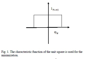
solution to the minimum area (A) problem is obtained in the limit, from a composite material containing suitable conductors and insulators as their microstructure, when they are thoroughly mixed. Also, the constrained composite conductor conductances are, C and D, respectively [1],[7]. Consequently, the design problem was to obtain the least composite area, that can carry the highest horizontal and vertical currents simultaneously (Fig. 1), and have the required conductor attributes [3],[5].
In isotropic composites (C = D), [1] indicates [8] obtained the optimal design using conducting rings around smaller insulated disks. For anisotropic composites (C φ D), ellipses were used to obtain the optimal design. Since [8] and [9] have proved that no other design could be better; we shall then use this result without proof in the paper.
2.2. Mat Design
Adopting the Mat pattern makes it easy and possible for the vertical currents to flow through the horizontal strips as their conducting paths and vice versa [1]. When the density of the vertical strip is G and the height of those strips is 1 - C, the vertical resistance of the composite becomes (1 - C)/G [3],[5].
Since the composite is in series with a conducting resistance strip C (to the vertical flow), the effective conductor properties become [1]:
Vertical resistance = C + (1 - C)/G Horizontal resistance = 1/C Conducting area A = C + G (1 - C)
The desired vertical resistance value 1/D, produces a current D with unit voltage drop [5]. Hence [1],

Consequently, the total conducting area becomes
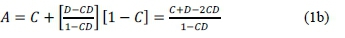
Equation (1b) above is the optimal area of the composite conductor. Coincidentally, and for small currents, the optimal area is near C + D. Furthermore, the economics of the interleaving composite matrix ensures that both the horizontal and vertical current modes can use each other's conducting paths because these conducting paths are fine, compact together, and rather indistinguishable [10].
2.3. Variational Problem
Suppose Q is the open unit square of the composite, having a unit voltage between χ = 0 and χ = 1, and a current flows. The vector has zero divergences because there are no sources or sinks inside the square. The vector describes a current function: u(x,y) by (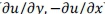 ).
).
For any u, this vector has divergence [11]:
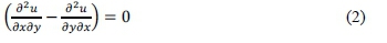
The above divergence equation (2) gives both the magnitude |Vu| and direction of the current at each point. For the insulated region, the magnitude |Vu| = 0 and the current function is constant. Hence,  = 0 is the normal derivative from both sides of the boundary. At the lower boundary of the square, u = 0 and the upper boundary of the square u = C, so that current C can flow from left to right [1],[5].
The increase in u(O) - u(P) is the current function that flows from O to Ρ [12],[13]. Since the conducting material has a unit-specific resistance, the heat loss, I2R in a single resistor, is

The current is obtained in the smallest possible conducting area A when it is flowing, because |Vu| Φ 0.
Then, the optimal bidirectional composite conductor problem becomes:
Minimize the area in which Vu, subject to:

The above one-dimensional problem in equation (4) is solved using a horizontal conducting strip of height C [1]. The current function is u = y for y < C; and u = C for y > C [12],[13]. Therefore, |Vu| = 1 inside the strip and |Vu| = 0, elsewhere. Thus, meeting the above constraints ensures that the conductor strip area C has the least value.
The constraint  indicates that the actual current minimises the above integral and satisfies Laplace's equation in the conducting area [12],[13].
Physically, the heat loss relationship is replaced by Green's identity to ease transformation, simplicity in representation, and solution to the problem [1],[7].

On the right side of equation (5) above, the only nonzero integral term is u(du/dn) along the top of the square, where u = C and J u(du/dn) ds = voltage drop = 1. Therefore:

The above unidirectional conductor problem is simple to solve and realize, and it is not convex. Consequently, the minimization of the area is the minimization of  , where 14 is a characteristic function (Fig. 1) [1],[11],[12],[13]. The step function equals unity in the set K, wherever
  and zero outside the set K, wherever
  .
.
Naturally, the Lagrange multiplier ( l) constraints minimise the 0 - 1 nonconvex integral problem whenever we can make  , as often as, practicable.
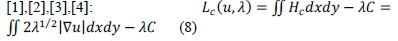
Therefore, the Lagrange multiplier functional is [1],[13] :

Fortunately, the integrand in equation (7) above has the Hessian functionals:  , that is relaxed, to realize acceptable solutions.
Moreover, for an unknown scalar, the relaxation is the same as its convexification [1],[2],[3],[4].
We use convex functions because there is one minimum point in the convex interval [14],[15]. Convexity unifies a wide range of phenomena [2],[3],[16], like the optimal bidirectional composite conductor software design validation problem under investigation in this paper.
Furthermore, every convex combination of points is in its epigraph. Therefore, a function is convex iff its epigraph is a convex set [2],[17],[18]. Hence, a convex function on a convex set A is converted to a convex function on Rn[17]. Similarly, a differentiable function f on a convex domain is convex, and the divergence of a convex function  = 0, indicates that the χ is a global minimum. Also, if f is differentiable twice on a convex domain A, it is convex iff the Hessian matrix H(x) is positive semi-definite for all
  [2].
[2].
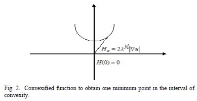
We replace Η by the greatest convex function satisfying Hc < Η without changing the minimum integral value (Fig. 2). Thus, the minimizing function u* is significantly changed, but the original L may not exist. In the one-conductor problem, Hcgrows linearly from its virtual bifurcation point having | | up to where A|Vu|2= 1 and Hcis tangent to H.
But, before that point, the convexified functional is
Minimizing u*, grows from zero at y = 0 to C at y = 1, and it is linear because u* = yC. Hence,  and the Lagrange functional is [1],[2],[3],[4]:

The maximum over λ occurs wherever λ* = 1, and gives the least area subject to the constraint: Optimal area = C.
But, /T|Vu*|2= C2 < 1. Consequently, the least conductor area appears where Hc, is lower than H. This homogenisation condition ensures that the composite conductor mat structure swings between Η = 0, and H = 1 + λ| |2. This is so because the average of Η is Hc[1]. Although the unidirectional conductor problem uses relaxation, the least area C is obtained without relaxation. However, the proof indicates that the least area used convexification, where λ = 1 and for any u: Area =

2.4. Bidirectional Optimal Conductor Problem
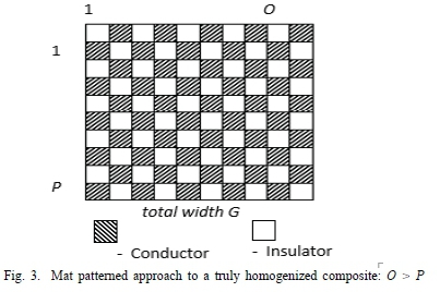
The bidirectional variational conductor problem requires two current functions u(x,y) and (x,y). The simple convexification procedure is not applicable, because the unknown vector quantity has magnitude and direction [13]. The mat design is divided into two regions R" and R2(Fig. 3). Using Green's identity, which is horizontally and vertically, simple, we divided the boundaries C and D of R into C" υ D" for boundary R" and C2 υ D2boundary R2[7]. The increase u(O) - u(P) is the current function [7],[8], that provides the flow from Ο to Ρ (Fig. 3).
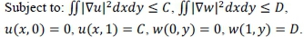
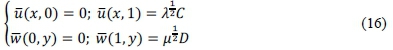
Additionally, the first part is constrained by u(x,0) = 0 and u(x,1) = C, while  = C, as in the unidirectional conductor case [1]. Similarly, the second part w shows that a vertical current D flows through the mat composite when a unit voltage is applied between the highest and lowest portions of the unit square [1],[3].
Also, wherever the horizontal and vertical currents are respectively zero,  = 0 and, Vw = 0, there is no need for conducting materials at such locations. Therefore, the bidirectional composite conductor problem occupies the set Κ values in the minimised area [1],[4],[7]:

Minimize area (K ) = J 14 dxdy
It was shown that the strips/mat design had minimal area: A = 
But, the 0-1 bidirectional composite conductor problem is not convex and is converted by the Lagrange multipliers λ and μ, into the unrelaxed functional: L(u, w, λ, μ) =

Equation (12) is convexified because the least value, Lcis small, since it is below L. The pseudoconvexification Lris the greatest functional below L, which shows the relaxation is small and partly continuous. Therefore, the minimizing functions u*, w * are feeble oscillation boundaries for L [1],[3],[4],[7].
Pseudoconvexity is laborious to test, but polyconvexity exists and can be tested. The relaxation [1],[3],[4],[7], Lr = JHr(Vu,Vw)dxdy, is polyconvex because Hris a convex function of \Vu\ and \Vw\, while the Jacobian determinant is

The Jacobian is not a convex 0-1 characteristic function of 18. It is made polyconvex by relaxation, homogenisation, and multilinearisations to form a family of upper envelopes of linear functions in J,\Vu\, and \Vw\. Convex functions are envelopes of linear functions of \Vu\ and \Vw\, but, a polyconvex function may not be convex. The unrelaxed integrand [1],[2],[3],[4],[7]:

Equations (14) above are vector transformations included in the Lagrange multipliers λ and μ into ü = Ä1/2u and w = μ1/2w. The Lagrange multipliers are positive parameters and the inequality constraints satisfy the design objectives. This is so because the bidirectional composite conductor design presents a lower resistance to either of the currents.
Also, the bidirectional composite conductor design obeys JJ\Vu\2 = C, and JJ\Vw\2 = D. The relaxation of Η is [1],[3]:
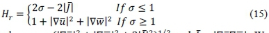
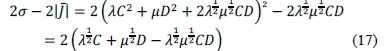
where σ = (\Vü\2 + \Vw\2 + 2\J\2)1/2and J = \VUVw\. We shall show that Hris polyconvex and Hr < H. We know that no pseudoconvex functions are between Η and Hr, provided that, the constraints are satisfied in the conducting area A' =

-. And, the area is not greater than A [1].
, the variational bidirectional composite conductor design problem is solved because Hris polyconvex. Hence, [1],[2],[3]:
Minimize J Hrdxdy subject to:
The above constraints satisfy linear functions:
The Jacobian functions are constant, which is the necessary and sufficient condition for pseudoconvexity. This is so because they satisfy the boundary conditions by producing the lowest possible solutions [1],[2],[3].
Additionally, the lowest value of  , after integration of a constant over the unit square, is [1],[2],[3]:
We realize that the final terms - in equation (18) below are as in the Lagrangian of equation (12), and we are left with a maximization over λ and μ. Therefore,
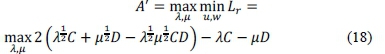
Differentiating equation (18) above with respect to λ and μ, and rearranging, the Lagrange multipliers become:
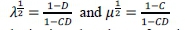
Substituting the above functionals into equation (18), we have

which is equal to area A, and this minimum occurs at σ < 1.
However, σ is equal to the density of the conducting material, and it is equal to (a = A). This is so because the density is a constant value over the unit square [1],[3].
Consequently, the area of the bidirectional composite conductor design is not less than A', because:
(a) Hr < Η since, Lr < L for each positive λ and μ
(b) Hris polyconvex, because its associated functional is least The constrained minimum area A' is equal to area A, as the mat design is approached.
Hence, the proof of polyconvexity using the computable convex functions technique will show that multilinear functions, having Hrenvelopes are below H. And, they produce the lowest possible solutions. Thus, the results come very simply and elegantly, as:

We then consider the two functions as:
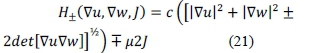
For either sign, the parameters in brackets are positive quadratic forms in Vu, Vw, and a sum of squares. The square root  , and constituents of
  are convex [2]. The linear Jacobian terms
  , make H±convex functions have supplementary parameters. Since Hris the larger of the two functions (H+), when J is equal to det[
 ], then Hris polyconvex [1],[2],[3].
We see that for c (τ) = 1 + τ2 and large τ, the H± functions are: 1 + |Vu|2 + |Vw|2. Besides, for small τ, the difference between H+and H_ depends on:

Equation (22) exists when m>n>0, and m + n < 1.
Our interest in this paper is to provide optimal solutions to the bidirectional composite conductor design problem; conduct a software validation study and discuss some composite conductor applications.

Therefore, the best solution occurs when ±det[VuVw] is equal to the absolute value |J|. Consequently, the parameter τ is equal to b in defining Hr, where max//+ is equal to Hr.
Solving equations (22) and (23) by applying the constraints, shows that: m = n, and m + n= 1, and the optimization conditions become:
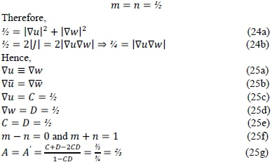
This (0,1) convex set is an optimal solution to the computable convex functions design of a bidirectional composite conductor software validation problem.
Also, the half (½) is a local maximum for grad (Vu), and the other half (½) is also a local maximum for grad w (Vw). Furthermore, any local optimum is also a global optimum, provided the constraints define a convex region. This optimisation is so because it describes linear functional [18].
Moreover, the gradient shows the direction of the greatest change along the line of equipotential or equal energy or of the value of F(x,y) [19]. Also, the Jacobian (J) tracks the distortion, whenever there is a change of coordinate system. It also mirrors the symmetry of the changes made in the coordinate system by substitution. It further measures the stretching, shrinking, or twisting of the substitution, which may result in a larger determinant of the representative matrix [20].
Although the gradient and Hessian analytically compare a derived gradient for correctness, the Hessian matrix computes the confidence interval values of parameters in maximum likelihood estimation. While the Hessian matrix as a minimizer should be positive definite, one of the eigenvalues of a semi-definite Hessian matrix will necessarily, be zero [21].
However, Hris below H simply because 2τ is smaller than 1 + τ2. The difference between the unit square and area occupied by insulator strips is the savings in the conductor area that was achieved by homogenization [1],[3],[22],[23].
2.5. Convergence Tests for Vertical and Horizontal Currents
Suppose each wire composite conductor matrix can accommodate two kinds of currents C and D, where the total number of currents in each wire adds up to N. If the wire is in state ek, k = 0,1,2, ...,N and consists absolutely k currents of type C and Ν - k currents of type D [24]. The probability that a new wire is in the state elis given by the hypergeometric distribution
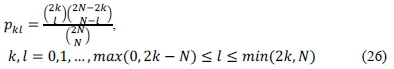
Let ek be the present state and probability of choosing the current type C in the next stage be ρ = k/N. If the Ν currents in the next stage are randomly chosen from Ν Bernoulli measurements, the C-current probability is equal to p. The transition probability that the next stage current has moved to state eB (I currents of type C and Ν - I currents of type D) from the state ekis the binomial distribution

The limiting behavior of total current based on these models after many stages can be determined because models e0and eNcontain currents of the same type and no exit from these states is possible [11],[13],[24]. Absorption probability transition matrices can be used to represent finite-chain Martingales. A martingale is a Markov chain when the expectation of probability distribution {pkl} equals k:

Let e0, β", ..., eNbe the states in a martingale and the system is absorbed either into e0or eN. If k = 0 and k = Ν in equation (28), we have p00= pNN = 1, because e0and eNare absorbing states [24]. Assuming these two are all the persistent states in the sequence, then e±,e2,...,eN_±are transient states, and the arrangement is absorbed into either e0 or eN. From equation (28), and by induction we have,

for all n. Actually,  for every transient state el, I = 1,2, ...,N - 1 and for k > 0, equation (29) provides the only solution

Because there are only two absorbing states, give

If the current starts from ek, the probability of the final kl absorption into e0and eN are  If all current states are equally likely to start with and then, finally be absorbed into eN, then:

Therefore, for a randomly selected initial distribution, final absorption into either e0or eNare both equally likely events for limited state martingale [24]. It follows that regardless of the actual process of the model, beginning from an initial state ekthe final absorption probabilities into e0 (all C currents) and eN(all D currents) are 1-k/N and k/N, respectively. Consequently, currents  -, which corroborate equation (25e). It follows that and by similar reasoning (substituting values into equation (19)) the optimal area A' tends to be two-thirds the unit area of the composite conductor design
  -=, which is in perfect agreement with equation (25g).
III. Simulation And Validation
Simulation is the mimicking of one system by another. It is used in two ways: (a) when uncertainty is high because of sparse or limited data, (b) for experimentation in a low-cost, low-risk environment. Furthermore, simulation is conducted by researchers before the validation of their forecasts in the expensive real world. Although simulation applications are useful, they have advantages and disadvantages.
The advantages of simulation include: (a) Study the behavior of a system without building it, (b) Results are accurate in general compared to analytical models, (c) Helps to find unexpected phenomena and behavior of the system, (d) Easy to perform, using "what-if analyses, (e) Forecasting under uncertainty, (f) Able to answer several questions, (g) Use low data requirements to model, (h) Low cost and (i) Innovative approaches can be applied [25],[26],[27].
The disadvantages of simulation include (a) Expensive to build a simulation model, (b) Expensive to conduct simulation, (c) Sometimes, it is difficult to interpret the simulation results, (d) Good theories are needed, (e) No standardized approach, (f) Challenging to validate, (g) Potential scope encroaches into projects, and (h) Political entanglements [25],[26],[27].
Also, simulation is an elegant approach to analyzing problems with limited data. It is so because we do not need data to design or construct a simulation. However, validating a simulation demands several data sources for a reliable representation of the real world. Thus, the process of validation is a disadvantage to simulation because validating simulations is usually more laborious to design [25],[26],[27].
3.1. Why Carry Out Bidirectional Composite Conductor Optimization Study?
We embarked on python software validation of the earlier work [3] in this study because [3],[28]:
(a) Conductor optimization is necessary for electricity network expansion planning
(b) To secure transmission lines infrastructure able to evacuate rising electricity generation and consumption capacities worldwide
(c) To support, enhance, and strengthen optimal power systems operators' response in emergencies
(d) To increase and maximize benefit-cost ratios, which enhance reliability improvements, reduce operational costs against initially high optimal bidirectional composite conductor investments
(e) To adaptively strengthen the interdependence between electricity conductor infrastructures and renewable energy uncertainties
(f) To minimize total investment costs, transmission lines losses, and optimally and efficiently engage, electricity production units
(g) To satisfy future load growth having additional security and operational constraints
(h) To minimize transmission lines rights-of-way difficulties
3.2. Policy Problem Formulation
The policy is to address some recurrent questions and challenges of the electricity industry [29] :
(a) To determine which and where optimal electricity lines are built for minimum investment costs that satisfy future energy requirements
(b) Transmission infrastructure directly and considerably impact optimal operations of electricity networks
(c) To minimize electricity production costs of power generation, which depend on fuel sources, technology, and transmission infrastructure for the supply
(d) Increasing future demand requires significant investments in electricity generators and transmission systems, which need additional capacities
(e) To develop and deploy more efficient and sustainable electricity transmission systems
(f) To educate and encourage energy suppliers to embrace new, efficient, and more sustainable transmissions systems infrastructure
IV. Results And Discussion
4.1. Results and Discussion of Mathematical Model Analysis
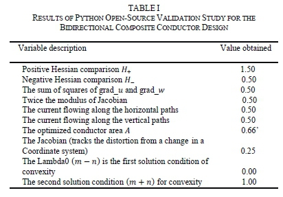
Table 1 in Appendix A indicates the results of the convexified variational bidirectional composite conductor software validation study. The study, software validated the composite conductor designs that carry high currents both horizontally and vertically. It used the minimum area without hotspots because of balanced loading. The density of conductor strips determines the vertical and horizontal resistances of the unit square. The divergence of the current functions of the variational problem evaluates the heat loss in the resistor. The minimized constrained currents satisfy Laplace's equation and Green's function identity.
Both the Lagrangian multipliers and the Hessian matrix convexified the scalar characteristic function. The convexified Hessian of the relaxed problem served as inputs to the software validation study. The python open-source computer codes of the results in Table 1 are shown in Appendix A.
The results in Table 1 show that a half (½) each was a local maximum for grad ( ), and grad w (
 ). Further, any local optimum is also a global optimum, provided the constraints define a convex region. Also, these optimization results describe linear functional [18]. In addition, the gradient indicates the direction of the greatest change along the lines of equipotential, or equal energy, or the value F(x,y) [19]. The Jacobian (J), which is a quarter (¼) tracks the distortion, whenever there is a change in the coordinate system. It mirrors the symmetry of the changes made in the coordinate system by substitution. It also measures the stretching, kinking, shrinking, or twisting of the new coordinate system leading to an alteration of the determinant of the representative matrix [20].
Additionally, the gradient (½) and Hessian [H+ = 1½; H~ = M] analytically compare the derived gradients for correctness. The Hessian matrix determines the confidence interval values on parameters in maximum likelihood estimation. Although the Hessian matrix as the minimizer should be positive definite, one of the eigenvalues of a semi-definite Hessian matrix will necessarily be zero [21].
The above semi-definite Hessian matrix condition was satisfied in this study because the eigenvalues were 0 and 1 (Convex functions). Additionally, the conductor materials occupied about two-thirds (%) of the unit square area A of the designed optimal bidirectional composite conductor proposed in the study.
However, both the vertical and horizontal currents flowing in the designed bidirectional composite conductor were half (½) each. The equality of currents between the horizontal and vertical components of the composite conductor matrix resulted in balanced current loading that does not create hotspots nor localized heating.
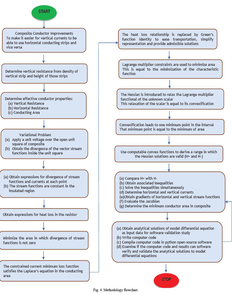
Moreover, Fig. 1 shows the characteristic function of the unit square. It used the Lagrangian multipliers, Green's function, homogenization, multilinearizations, polyconvexity, and Hessian matrices to achieve the minimization of conductor strips. Fig. 2 shows the representations of the convex function of the gradients and the convexified Hessian functionals used to achieve one minimum point in the interval of convexity, which was also a global optimum. It also supports the claim and objective of using the minimum conductor area to show that, the bidirectional composite conductor design was optimal. Fig. 3 shows the mat structure of the proposed optimal bidirectional composite conductor that was homogenous in the interleaving of insulator and conductor strips able to conduct high currents vertically and horizontally, in which the vertical currents can follow the horizontal paths and vice versa. Fig. 4 shows the methodology flowchart for the study. It also represents the step-by-step operations used to realize the body of work in the paper.
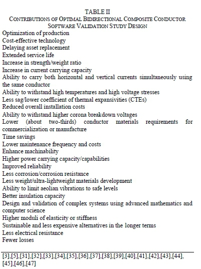
Furthermore, Table 2 shown in the Appendix indicates the contribution of the bidirectional composite conductor software validation design in this study. The next subsection 4.2 discusses software validation.
4.2. Software Validation
Although the bidirectional optimal composite conductor design has been built around the minimization criteria for the conductor area, the ability to carry maximum currents both vertically and horizontally, at the same time, remains the major contributions and benefits of the study. While simulation is used to mimic a system by another because of the paucity of data, validation of design requires ample data for a reliable representation of the real world. Therefore, verification and validation of the results of differential equations become vital for simulation processes. Thus, verification determines if the result of the simulation approximates the precise solutions to the differential equations of the original model. In contrast, validation determines if the chosen model is an adequate representation of the real-world system for the simulation [25],[26],[27].
Verification is divided into (a) solution verification, and (b) code verification. Hence, solution verification confirms that the output of the intended algorithm approximates the precise solutions to the differential equations of the original model. However, code verification confirms that the code as it is written performed the intended algorithm. More importantly, benchmarking solutions are premised on verifying solutions, which compare computed output with analytical solutions [25],[26].
From the epistemology of simulation, the dichotomy between verification and validation is not so subtle. There are overlaps and sometimes, real difficulties arise in defining one without the other. A help emanates from [30] as quoted by [26], that: "Verification deals with mathematics and addresses the correctness of the numerical solutions to a given model. Validation, on the other hand, deals with physics and addresses the appropriateness of the model in reproducing experimental data. Verification can be thought of as solving the chosen equations correctly, while validation is choosing the correct equations in the first place."
Further, simulation results show that any local optimum is also a global optimum in the region of convexity. Hence, both local maxima and global maxima occurred for the: (a) Horizontal currents, (b) Vertical currents, (c) Gradient of the vertical functional, (d) Gradient of the horizontal functional, and (e) The constraints. Moreover, the gradient, which is the direction of the greatest increase maximizes the varying tradeoffs, while the Jacobian tracks the distortion, stretching, or kinking of the change in the coordinate system [2],[18],[19],[20]. The next section discusses composite conductors and their applications.
V. Applications Of Composite Conductors 5.1. Earlier Composite Conductors
Earlier composite conductors were designed from two separate wires considering their physical and electrical properties. Aluminum conductors steel reinforced (ACSR), aluminum conductors aluminum alloy reinforced (ACAR), and all-aluminum-alloy conductors (AAAC) are long-span used in overhead transmission and distribution lines [31]. Air-expanded ACSR is an increased hollow diameter conductor used to create air spaces for cooling and minimize corona effects. Its increased current-carrying capacity, better skin effects, and using lesser metal enable it to operate at higher temperatures above 300 kV [32]. Self-supporting ACSR limits aeolian vibrations to safe levels, ACSR/TW because of smaller diameter and smooth surface experience lower wind loading. T2 conductors comprise two spiral windings from twisted standard ACSRs and significantly reduce wind-induced galloping because ice cannot form along conductor length. Steel-supported aluminum conductors (SSAC) have high electrical conductivity at high temperatures and better sag-tension properties [32].
5.2. Power Blackouts
Electrical transmission and distribution lines outages mostly come from thermal sags, when the current passing through the conductor exceeds transmission capacity. Overheated wires elongate to cause sags, which potentially violate minimum ground clearances leading to arcing faults, short circuits, and cascading failures [3],[33]. Thermal sags caused the August 14, 2003, US East Coast blackout, leaving over 50 million people without power [34]. The July/August 2012 India blackout that made over 710 million people of the Indian subcontinent without power was due to sags [35]. A combination of weak monsoon, low hydropower generation, high temperatures, high humidity, and increasing electricity consumption to cool the heat and discomfort experienced, caused the monumental collapse of the Indian power system [36].
On 2nd July 1996, a Western US power blackout occurred because of a short circuit in transmission lines from the Bridger coal-fired generator of Idaho Power affecting over 7.5 million people. A disconnection of three 500 kV lines caused heavy power flow North-South. Consequent overload caused 230/115 kV lines to disconnect leading to voltage declines, tripping power units, power oscillations, cascading separations, and power blackout [37]. North Eastern U.S. and Canada blackout of 14th August 2003 affecting over 50 million people occurred like those of 1996. A 500 kV line disconnected causing heavy power flow South-North. Another 500 kV line sags into a tree and disconnects making 230/115 kV lines to disconnect. Several 345 kV lines trip, voltage declines, power units trip, power oscillates causing voltage declines and cascading separations leading to blackout, later [37].
Over 57 million people were affected in the Italy 2003 power failure because 6 GW heavy power import to Italy caused one 380 kV line to sag into a tree and disconnect. Parallel 220/110 kV line sags into another tree because of overload to completely isolate Italy. Consequent voltage declines, power units trip, power oscillates, voltage further declines to cause cascading separations, and blackout [37]. However, using the proposed optimal bidirectional composite conductor designs validated in this study can drastically reduce thermal and cable sags in power systems networks, worldwide.
5.3. High-Temperature Low-Sag Composite Conductors (HTLS)
HTLS conductors retain their shape integrity at higher temperatures, lower thermal expansivity coefficients (CTE), and higher ampacity (ampere capacity) for transmission. CTC Global hybrid carbon/glass fiber aluminum composite core conductors (ACCC), has low CTE, low sag, operational temperatures between 1800 and 2100C, can carry twice ACSR current and less sag [3],[33]. Between 2006 and September 2012 over 14,806 km ACCC were installed in over 220 projects worldwide. Also, ACCC re-conductored 345 kV 2,680 km American Electric Power (Columbus, Ohio), 893 km power line in Texas, and 18 mm diameter ACCC conductors replaced 69 kV 32 km long, old copper conductors, in Nevada in 2009 [33]. Lightweight and fire resistance made felled conductors to be re-energized after replacing burnt H-frame. They have been installed in over 24 countries, including Russia [33].
3M's aluminum conductor composite reinforced (ACCR) cable uses a metal-matrix composite core design. Its CTE is half that of steel. 3M doubled manufacturing capacity and supplied over 2,575 km ACCR conductors to 13 countries except for Australia and Antarctica. By 2013, 3M manufactured 135 to 828 mm2 product lines using alumina ceramic oxide (AkO3) powder made into a gel. It is extruded through spinnerets to form embedded core fibers in high purity aluminum. Customer size/strength requirements enable 7 to 19 core aluminum zirconium (Al-Zr) stranded wires as twisted cable to operate continuously at 2100C and peaks at 2400C [3],[33].
EDP Escelsa (Brazil) in 2012 replaced its sagging power lines over the Rio Doce River in Linhares (918 m span) by ACCR and doubled the 138 kV line ampacity with a better line clearance, without requiring new rights-of-way permits and new construction efforts. Georgia's power saved between US$ 15 and 20 million to upgrade 54.7 km 230 kV power transmission line using ACCR. It served Savannah power 10 weeks in fall and 10 weeks in spring, at low demand periods during 2011 and 2012 [33]. Utah Power Utility cost- effectively reconductored a section of its transmission lines with CTC cables and replaced only 7 instead of 150 support towers, if it used conventional ACSR to strengthen its transmission capacity. It could meet projected electricity demand for the next 15 years without building new transmission lines [3],[33].
5.4. Power Line Analysis Tool (PLAT)
Although many benefits derive from composite conductors, the equivalency of composite-for-steel-cored cable conversions in the power industry has faced acceptance difficulties. Reference [38] indicates despite the upfront cost of developing and commercializing composite conductors, the equivalency of composite-for-steel-cored cable is the most difficult aspect of their sale to customers long used to some other technology. To break that barrier, Composite Technology Corporation (CTC) designed Power Line Analysis Tool (PLAT) software to compare, contrast, and evaluate the electrical and physical performance characteristics of available cable products based on twelve linked screens. It helps engineers, project managers, and other professionals in the power industry to select cable sizes (diameters), power capacity, cable sags, seasonal weather performance features, estimated installation costs, and computation of cost savings over the expected useful life of the cable [38].
5.5. Linking Composite Conductors with Cabling
Conductor composites connect seamlessly with the physical, electrical, and mechanical characteristics for specialized applications. These include power systems transmission cables, subsea cables on off-shore platforms, standing to rig on yachts, cable stays on bridges, solar-powered cars, and solar-powered aircrafts. These occur because of composite for metal replacement processes. These have also proved very useful and economical especially when viewed from structural and components integrity considerations [39].
Overheating and sag have plagued conventional ACSR cables. Replacing them with composite HTLS conductors provides: long-term durability, little or low maintenance, removes rights-of-way permit problems, corrosion resistance, higher ampacity, higher working temperatures, little or no tower replacements, fewer losses, longer spans, higher electrical loads, and significantly reduced installation cost. The global market for composite cored cables is over US$ 50 billion annually to strengthen the existing power infrastructure [3],[39].
Further, ACCC is constructed using a pultrusion process in which carbon fibers are drawn unidirectionally along 00-axis to form, the cylindrically shaped core around E-glass oriented fibers at the exterior. They are wetted out with high-temperature resistant epoxy resin to separate carbon from conductive aluminum overwrap that prevents metal solution and galvanic corrosion [3],[5],[39]. The process makes brittle carbon more malleable, enhances the flexibility and robustness of the composite ACCC core. This same carbon structure makes the tail section of the Boeing 777 jet [3] that is intricately linked to its efficient braking system. Thus, the wet ACCC fiber bundle is cured at 2600C, and core conductor sizes range from 12.7 mm to over 69.85 mm. They carry between 300 and over 3500 amps per line in ampacity range and these high currents are suitably controlled at high tension of 18,597 kg [39].
While fiber availability, lack of standards, testing/inspection methodologies, customers continued adherence to ACSR cables, quality, and very high upfront costs are disadvantages of composite cables [39], price, weight reduction, processing renewable resources, production using low investment, thermal recycling possibility, good thermal and acoustic insulating properties are advantages of using natural fiber composites for technical applications [40]. However, lower impact strength, weather-dependent quality variability, hygroscopic swelling, limiting maximum processing temperature, poor fire resistance, harvest-dependent price fluctuations or on agricultural politics, thinning, knots, ties, voids, and imperfections in natural fibers are the major drawbacks [40].
5.6. Subsea Cables
Subsea composite cables used in offshore oil rigs for continuous movements from shallow waters to deep waters up to 2,000 miles (3,220 km) deep have low weight, high stiffness/strength-to-weight ratio to support high stiffness/low sag and low elongation properties. Further, offshore operators need to avoid paying the higher costs for carbon fiber with termination difficulties made Aker Kvaeman Subsea, Norway, and Conoco Philip (Houston, Texas) develop carbon-composite cables used in steel for anchor tension leg platforms (TLPs). It is used in carbon-stiffened, hollow-umbilical cables, to carry electrical, fiber-optic sensing, and other service lines [39].
5.7. Bridge Cable Stays
Bridge cable stays are supports for deck or girder systems. They use a series of cables attached at regular intervals, strung diagonally to attachment points on one or more vertical supports. Bridge cable stays are durable in the longer term, corrosion-resistant, and low need for maintenance. These advantages offset the initially great upfront capital outlay [39].
5.8. Yacht Rigging
The major objective for composite conductor use in Yacht rigging is weight reduction. For every 0.45 kg weight removed from the top of the mast, about 3.6 kg of ballast is removed from the yacht keel. Many tonnes of yacht structural strength requirements are reduced to minimize material costs, yacht becomes faster and more responsive without losing stability, thereby saving between 60 and 70 percent in weight compared to steel they replace, without compromising strength. The disadvantage of fiber elongation is eliminated by increased composite rigging cross-section [39].
Element C6 carbon cables are bundles of 1 mm diameter rods with 227 kg tensile strength capable of customized performance requirements. They are 50% stronger than stainless steel at a fraction of its density. About 34 bundled rods have a breaking strength of 5,715 kg and a maximum stress capability of 2,551 MPa. They are encased in carbon or aramid brand protective jackets for better grip because cable tensions increase simultaneously with an increase in the compressive load of the terminus plug, which is distributed evenly along the full length of the rod bundle [39].
5.9. Custom Composite Rigging Cable
Custom composite rigging (CCR) cable design assembles parallel nested hexagonal tension rods pultruded (pulling through) using 60 to 70% carbon volume fiber and epoxy resin binder. Complementary dual tapering along their lengths removes stress concentrations at load points. Stainless steel or titanium-coated shanks at end terminals prevent corrosion between metal and carbon [39].
5.10. Petroleum Pipelines Anti-Corrosion Control Systems New lease of life was given to internally corroded
petroleum oil pipelines earmarked for closure using AntiCorrosion Protective Systems (APS) in 2013. In-Field-Liner (IFL) is an innovative composite liner system of the corrosion-resistant barrier, between highly corrosive hydrogen sulfide medium produced by sulphate-reducing bacteria (SRB) in crude oil that causes damage or rupture to steel pipeline structures [40]. In 2014, gas pipelines totaling 4 km were installed in four other PETRONAS Cargali locations in West Lutong fields of Sarawak in Malaysia. The service lives of pipelines were extended by beyond 30 years, and saving over 50% of pipeline capital replacement costs [41].
The success of APS's IFL technology for oil, gas, crude and multiphase mixtures, enabled the rehabilitation of over 10 subsea pipelines running between platforms operating at temperatures up to 1100C. PETRONAS saved over US$ 100 million using IFL technology [42]. In 2015, PETRONAS Malaysia awarded two multi-year contracts to APS (Dubai, UAE) worth US$ 150 million to rehabilitate much subsea crude oil gathering and high-pressure gas and condensate lines.
5.11. Cured-In-Place Pipe (CIPP)
Alternative on-land rehabilitation and repair lining using cured-in-place pipe (CIPP) resulted in significant time and cost savings for sewer lines (on-and-offshore fields), petrochemical plants, drinking water, foul outflow, gas, and pressurized water distribution. Although CIPP has great potential in the rehabilitation/repair composite market, IFL has future potential in the rehabilitation/repair market for undersea/underwater applications [41].
5.12. Solar-Powered Car Design
Composite technology consistently made solar-powered composite car designs win racing competitions, consecutively. The redesigned 190 kg carbon composite car ran its fourth race in Australia for a total of 3,000 km from Darwin in the North to Adelaide in the South of Australia in October 2007. The race had no blaring engines, screeching tires, or smell of fuel, or smoke. Everything was quiet but powered by the strong Australian sun [44].
All Nuna1-3 designs were carbon composites instead of aluminum. Weight advantages, higher specific strength, and stiffness, led to better fatigue properties and significantly reduced parts. Nuna4 was a semimonocoque design. Its aircraft wing-like shape experienced only one-sixth drag of comparable automobile. Solar cells on top of the relatively flat horizontal surface produced enough energy to power the electric motor on the rim of the rear wheel, about 100 km/h [44].
The rear suspension system was infused with carbon fibre and Turane urethane resin cured at 800C. The thermal resistance of Turane resin was adjusted to withstand Australia's ambient temperature between -200C and 600C. The urethane is stable dimensionally, but the composite begins to soften between 950C and 1500C. Air-sprung shock-absorbers design combines dampers and springs systems. The front wheels are aluminum while the rim of the rear wheel is composite strengthened with carbon and aramid fiber. However, C-profile stiffeners incorporated into the chassis and top shell of the driver's seat provide needed strength, and to further reduce weight [44].
Although it is not clear if solar-powered cars can replace petroleum inland transportation systems, solar power is being sustainably and inexpensively used in residential heating and electricity supply [45] as in space exploration of using rovers for Mars exploration [44].
5.13. Solar-Powered Aircraft Design
Solar Impulse 2 is the second generation of Si2 first solar-powered aircraft. Solar Impulse sought North Thin Ply Technology (NTPT), Switzerland assistance to make very thin unidirectional carbon fiber spread because NTPT offered outstanding composite strength, homogeneity, and machinability for rigid commercial applications demanding high performance and low weight [46].
In July 2010, Decision built Solar Impulse 1 (Si1), the first solar-powered aircraft that stayed a total of 26 hours in the air solely on solar power (even after dark). Si2 construction began in 2011 included an increased payload. Electrical circuitry was isolated to enable flight during light rain, and system redundancy to improve reliability. The cockpit was more spacious to enable the pilot to fully lay on their back during flights that could last for five days and five nights [46].
Solar Impulse 1 flew all night in 2010. Solar Impulse 2 flew halfway around the world in 2015. It journeyed from Abu Dhabi in the United Arab Emirates (UAE) on 9th March 2015 to Oman, India, Myanmar, China, and Japan (eight stops). It flew nonstop for almost five days (117 hours 52 minutes) to arrive in Honolulu, Hawaii on July 3rd, 2015 at 5.55 am. The average speed was 47 km/h [47].
Extremely thin composite Si2 main and rear wing spars, body, and tail were thin-ply (or spread-tow) tapes (prepregs), constructed using individual carbon fiber tow spreads, which separate the flattened fibers into a wider and much thinner unidirectional tape. However, Si2 was grounded in Hawaii from July 3rd, 2015 to 2016, because of battery problems and not from composites failure [47].
Si2 72 m wingspan is longer than the 60 m wingspan of Boeing 787 Dreamliner. The plane's fibre architecture is strong, lightweight, can withstand spar box torque resistance, and satisfy bend stiffness requirements. The cockpit was a low-density rigid polyurethane foam of 180 μm cross-section, about 40% below standard 300 μm cell density (or mass) [47]. Cockpit windshield of Covestro's transparent polycarbonate protected pilot and instruments, because the outside temperature could fall to -500C, and still able to maintain a planned temperature in the cockpit [47].
However, the worth of Si1 and Si2 solar aircraft industrialization endeavors gained expertise, know-how, and developed network over the years in energy efficiency, ultralight materials, complex systems design, solar production, energy storage cycle, and electric motors. Solar-powered drones are developed and promoted by organizations like Google, Airbus, and Facebook, for internet access, disaster relief, environmental damage detection, and assessment [47].
VI. Conclusions
The convex set was used to obtain optimal solutions to the bidirectional composite conductor software validation problem, in this paper. Further, the local optimum was also the global optimum, for both the currents and gradients of the optimal bidirectional composite conductor design in the region of convexity. The materials and costs optimization was so because the gradient shows the direction of the greatest change along the line of equipotential or equal energy. The Jacobian tracks the distortion, mirrors the symmetry, and measures the stretching, shrinking, or twisting of the changes to the new coordinate system. Also, the Hessian, as a minimizer analytically compares a derived gradient for correctness and evaluates the confidence interval values of parameters for maximum likelihood estimation.
Composite conductors commonly comprise two different wires with separate characteristics. They minimize corona effects, increase current-carrying capacity at higher temperatures, limit aeolian vibrations to safe levels, lower wind loading, reduce wind-induced galloping, acquire high electrical conductivity, and better sag-tension properties at high temperatures.
Cable and thermal sags occur when currents passing through the conductors exceed transmission capacity. The overheated wires elongate and cause sags, which potentially violate minimum ground clearances. Further, cable and thermal sags were implicated in the major blackouts of catastrophic proportions worldwide and their occurrences could be significantly reduced if the bidirectional composite conductors designed and software validated in this study could be deployed in future power systems networks worldwide.
Also, the CTC Global hybrid carbon/glass fibre ACCC and 3M's ACCR have low CTE and low sag. Their operational temperature ranges between 1800 and 2600C and can carry twice as much current as ACSR of similar dimensions. They are also able to carry currents between 300 and over 3500 A per line in their ampacity range.
The subsea composite cables have low weight high stiffness/strength-to-weight ratio. They are used in deep offshore for high stiffness/lower sag and lower elongation properties. The carbon-stiffened, hollow-umbilical cables carry electrical, fiber-optic sensing, and other service lines.
Current technological developments in composite conductors have led to frontiers in energy efficiency, ultralight materials, complex systems design, solar production, energy storage cycle, and electric motors. Other benefits include optimization of production from existing assets, focus on innovation, cost-effective technology, delaying assets replacement, extending service life, better strength-to-weight ratios, lower thermal expansivity coefficients, higher moduli of elasticity (or stiffness), and lower electrical resistance.
Economically, longer spans between towers lead to a reduction in the number of towers, which carry the greater electrical load by close to 20% and significantly reduce installation costs.
However, the major drawbacks to composites conductor commercialization include fiber availability, lack of standards, testing/inspection methodologies, customers continued adherence to the traditional ACSR cables, quality, and very high upfront costs.
Furthermore, the demerits of natural fiber composites include low impact strength, weather dependent quality variability, hygroscopic swelling, limited maximum processing temperature, poor fire resistance, harvest dependent price fluctuations, or based purely on agricultural politics, thinning, knots, ties, voids, cracks, and other imperfections.
Above all, the optimal bidirectional composite conductor design software validation proposed in this study shows one of the most innovative ways of using results of differential equations to make maximum use of the conductor materials in the design of using very tiny strips, and the advantage of minimizing cross-sectional area, and possible total elimination of galvanic corrosion, and metal solution problems.
References
[1] G. Strang and R. Kohn, "Optimal design of a two-way conductor," in Topics in Nonsmooth Mechanics, J. J. Moreau, P. D. Panagiotopoulus, and G. Strang, Eds. Basel: Birkhauser Verlag, 1988, pp. 143-155.
[2] G. N. O. Asemota," On a class of computable convex functions," Can. J. Pure Appl. Sc., vol. 3, no. 3, pp. 959-965, 2009. [ Links ]
[3] G. N. O. Asemota, "Optimal two-way conductor design using computable convex functions approach," Adv. Mat. Res., vol. 367, pp. 75-81, 2012, 10.4028/www.scientific.net/AMR.367.75. [ Links ]
[4] S. Takriti, "The unit commitment problem," in Operational research in Industry,T. A. Ciriani, S. Gliozzi, E. L. Johnson, and R. Tadei, Eds. London, UK: MacMillan, pp. 299-322, 1999, 10.1057/9780230372924.
[5] G. N. O. Asemota, "Optimal two-way conductor design using computable convex functions approach," in Proc. 3rd ICERD, Benin City, Nigeria, 2010.
[6] J. J. Moreau, "Bounded variation in time," in Topics in Nonsmooth Mechanics, J. J. Moreau, P. D. Panagiotopoulus, and G. Strang, Eds. Basel: Birkhauser Verlag, 1988.
[7] C. H. Edwards and D. E. Penney, Calculus. New Jersey, NJ, USA: Prentice-Hall, 2002.
[8] Z. Hashin and S. Shtrikman , "A variational approach to the theory of the elastic behavior of multiphase materials," J. Mech. & Phys. Solids., vol. 11, no. 2, pp. 127-140, Mar.-Apr. 1963, 10.1016/0022-5096(63)90060-7. [ Links ]
[9] F. Murat and L. Tartar, Optimality conditions and homogenization: nonlinear variational problems. (Isola de'Elba, 1983). London, UK: Roman Publishing, pp. 1-8, 1985.
[10] V. K. Mehta and R. Mehta Principles of Power System. New Delhi, India: S. Chand, 2007.
[11] C. F. Gerald and P. O. Wheatley, Applied Numerical Analysis. Massachusetts, MA, USA: Addison-Wesley, 1999.
[12] M. S. Naidu and V. Kamaraju, High Voltage Engineering. 2nd ed. New Delhi, India: Tata McGraw-Hill, 2007.
[13] F. B. Hildebrand, Advanced Calculus for Applications. New Delhi, India: Prentice-Hall, 1977.
[14] T. Moon, "Convexity and Jensen's inequality," 2000. Accessed on: Dec. 5, 2007 [Online]. Available: http://www.neng.usu.edu/classes/ece/7860/lecture2/node5.html
[15] L. Potter, "Convexity," 2005. [Online]. Available: http://cnx.org/content/m 10328/latest/
[16] E. Fink and D. Wood, "Fundamentals of restricted-orientation convexity," 1996. Accessed on: Oct. 18, 2007 [Online]. Available: citeseer.ist.psu.edu/38250.html
[17] G. Lebanon, "Convex functions," 2006. Accessed on: Dec. 5, 2007 [Online]. Available: http://www.cc.gatech.edu/~lebanon/notes/convexFunctions.pdf
[18] C. M. Bishop, Pattern Recognition and Machine Learning. Singapore: Springer, 2008.
[19] Betterexplained, "Vector calculus: Understanding the gradient- better Explained," [Online]. Available: https://betterexplained.com/articles/vector-calculus-understanding-the-gradient/
[20] Whitman. "16 Vector calculus," [Online]. Available: https://www.whitman.edu/mathematics/multivariable16VectorCalculus.pdf
[21] P. A. Brodtkorb and J. D'Errico. Numdifftools Documentation Release 0.9.20.post0.dev144+ ng9114a1a. 2018. [Online]. Available: https://media.readthedocs.org/pdf/numdifftools/latest/numdifftools.pdf
[22] S. Bimenyimana, G. N. O. Asemota, and P. J. Ihirwe, "Optimization comparison of stand-alone and grid-tied solar PV systems in Rwanda," Open Access Lib. J., vol. 5, no.5, pp. 1-18, 2018a, 10.4236/oalib.1104603. [ Links ]
[23] S. Bimenyimana, G. N. O. Asemota, P. J. Ihirwe, and L. Li, "Clustering residential electricity consumption: a case Study," in Proc. ACM Digital Library, Tianjin, China, 2018b, pp. 121-128. ISBN: 978-1-4503-6541-3
[24] A. Papoulis and S. U. Pillai, Probability, Random Variables and Stochastic Processes. New Delhi, India: Tata McGraw-Hill, 2008.
[25] X. Meng, "Simulation CSCI 6337: advantages and disadvantages," [Online]. Available: https://www.eg.bucknell.edu/~xmeng/Course/CS6337/Note/master/node3.html
[26] E. Winsberg, "Computer simulations in science. Stanford encyclopedia of Philosophy," 2015. [Online]. Available: https://plato.stanford.edu/entries/simulations-science/
[27] D. Duzevik. Advantages and disadvantages of simulation. 2017. [Online]. Available: https://concentricmarket.com/blog/advantages-and-disadvantages-of-simulation/
[28] Y. Hu, Z. Bie, T. Ding, and Y. Lin, "An NSGA-II based multi-objective optimization for combined gas and electricity network expansion planning," Appl. Energy., vol. 167, pp. 280-293, 2016.
[29] M. Jakubcionis and J. Carlsson, "Estimation of European Union residential sector space cooling potential," Energy Policy. Vol. 101, pp. 225-235, 2017. [ Links ]
[30] S. Roy, "Recent advances in numerical methods for fluid dynamics and heat transfer," J. Fluid Eng., vol. 127, no. 4, pp. 629-630, 2005. [ Links ]
[31] J. J. Burke and A. L. Clapp, "Power distribution," in Standard Handbook for Electrical Engineers, 14th ed., D. G. Fink and W. H. Beaty, Eds. New York, NY, USA: McGraw-Hill, 2000, pp. 18-72-18-76.
[32] C. B. Rawlins, J. Tanaka, D. J. Barta, C. A. Harper, T. W. Dakin, J. Stubbins, and D. E. Lyon, "Properties of materials," in Standard Handbook for Electrical Engineers, 14th ed., D. G. Fink and W. H. Beaty WH, Eds. New York, NY, UAS: McGraw-Hill Handbooks, 2000, 4-2-4-39.
[33] D. Dawson, "Composite-cored conductors: Holding the line," 2013. [Online]. Available: https://www.compositesworld.com/articles/composite-cored-conductorsholding-the-line
[34] J. R. Minkel, "The 2003 Northeast blackout-Five years later," 2008. [Online]. Available: https://www.scientificamerican.com/article/2003-blackout-five-years-later/
[35] H. Pidd, "India blackouts leave 700 million people without power," 2012. [Online]. Available: https://www.theguardian.com/world/2012/jul/31/india-blackout-electricity-power-cuts
[36] R. Bedi and R. Crilly, "World's biggest ever blackout as India is brought to a standstill," The Telegraph. (July) 2012. [Online]. Available: https://www.telegraph.co.uk/news/worldnews/asia/india/9441940/Worlds-biggest-ever-blackout-as-India-is-brought-to-a-standstill.html
[37] G. N. O. Asemota and F. B. Gahimano, "Symmetrical fault currents determination at 70-110 kV primary of Electrogaz grid in Rwanda," ZambianEng., vol. 41, no. 1, pp. 48-55, 2008. [ Links ]
[38] D. Dawson, "Modeling software facilitates composite-for steel-cored cable conversion," 2006a. [Online]. Available: https://www.compositesworld.com/articles/modeling-software-facilitates-composite-for-steel-cored-cable-conversions
[39] D. Dawson, "Composites connect with the world of cabling," 2006b. [Online]. Available: https://www.compositesworld.com/articles/composites-connect-with-the-world-of-cabling
[40] G. N. O. Asemota, "Critical angle estimation of light in plantain fibres," Can. J. Pure & Appl. Sc., vol. 5, no. 3, pp. 1693-1699, Oct. 2011. [ Links ]
[41] D. Dawson, "Composites extend service of oil and gas pipelines," 2015. [Online]. Available: https://www.compositesworld.com/articles/composites-extend-service-of-corrosion-prone-oil-and-gas-pipelines
[42] J. Sloan, "Composite liner for subsea oil and gas nears readiness," 2017. [Online]. Available: https://www.compositesworld.com/news/composite-liner-for-subsea-oil-and-gas-nears-readiness
[43] Staff, "In-field-liner installations helps to extend service life for Petronas subsea pipelines," 2016. [Online]. Available: https://www.compositesworld.com/news/infield-liner-installations-helps-to-extend-service-life-for-petronas-subsea-pipelines-
[44] D. Dawson, "Focus on design: solar-powered composite car designed to Win," 2007. [Online] Available: https://www.compositesworld.com/articles/focus-on-design-solar-powered-composite-car-designed-to-win
[45] S. Bimenyimana, G. N. O. Asemota, C. M. Kemunto, and L. Li, "Shading effects in photovoltaic modules: simulation and experimental results," in Proc. 2017 2nd IEEE- ICPRE, Chengdu, China, 2017, pp. 904-909, 10.1109/ICPRE.2017.8390665
[46] D. Dawson, "Spread-tow technology takes off," 2014. [Online]. Available: https://www.compositesworld.com/articles/spread-tow-technology-takes-off-
[47] D. Dawson, "Solar impulse 2: pulse on the future," 2016. [Online]. Available: https://www.compositesworld.com/articles/solar-impulse-2-pulse-on-the-future

Godwin Norense Osarumwense Asemota (M'2004-SM'2013): became a Member (M) of IEEE in 2004 and a Senior Member (SM) in 2013. He holds a B.S. in physics, post graduate diploma in electrical and electronics engineering, M.S. in ι electronic and electrical engineering, j MBA in finance and banking, and I Ph.D. in electrical engineering. He researches in electricity load management, power systems engineering, convex functions mathematics, plantains biology, finance and banking, renewable energy systems, power systems control, and optimization.
He taught high voltage engineering, power systems engineering, power plants engineering, and research methodology at the Kigali Institute of Science and Technology (Now College of Science and Technology, University of Rwanda, Kigali, Rwanda). He is currently at the African Centre of Excellence in Energy for Sustainable Development, University of Rwanda, Kigali, Rwanda and Morayo College, Nairobi, Kenya.
Dr. Asemota has published over seventy journal articles and conference papers, Electricity Use in Namibia, iUniverse, 2013, and Application of Modern Load Flow Techniques to Electric Power Systems, Lambert, 2010.
Professor Nelson Ijumba is the International Research and Innovation Programme Manager, based in the Africa Hub of Coventry University. He is Emeritus Professor of Electrical Engineering at the University of Rwanda, based in the African Centre of Excellence in Energy for Sustainable Development (ACEESD), and also an Honorary Professor of Electrical Engineering, at the University of KwaZulu Natal, South Africa. He has over 40 years of experience in teaching, research, consulting and academic leadership.
His research and consultancy services are in green energy, renewable energy resources exploitation, energy efficiency, electrical power systems, high voltage technology, innovation, higher education management and engineering education. Prof Ijumba is passionate about the impact of technologies on sustainable development and translation of research outputs into socially relevant innovative products. Professor Ijumba graduated from the University of Dar es Salaam (Tanzania), and obtained his Master's and Doctoral degrees from the Universities of Salford and Strathclyde (United Kingdom), respectively. He is a Fellow of the Southern African Institution of Electrical Engineers, a Senior Member of the Institute of Electrical and Electronics Engineers, a Member of the Institution of Engineering and Technology. Professor Ijumba is a Member of the Academy of Sciences of South Africa and a Fellow of the South African Academy of Engineering.
He is a registered Professional Engineer with the Engineering Council of South Africa; the Engineering Registration Board of Tanzania and a Chartered Engineer of the United Kingdom Engineering Council. He has published widely in indexed journals and made numerous presentations at international and local conferences.
This paper was submitted on 24 October 2020 for review. This work was funded by the African Centre of Excellence in Energy for Sustainable Development, University of Rwanda, Kigali, Rwanda.
GNO Asemota is with Morayo College, Nairobi, Kenya and African Centre of Excellence in Energy for Sustainable Development, University of Rwanda, Kigali, Rwanda (e-mail: asemotaegno@gmail.com).
NM Ijumba is with the School of Engineering, University of KwaZulu-Natal, Durban, South Africa and African Centre of Excellence in Energy for Sustainable Development, University of Rwanda, Kigali, Rwanda (e-mail: n.ijumba@ur.ac.ur).
Appendix A
A.I. The Compiled Python Open-Source Software Program
# The solution to the two-way optimal composite conductor
problem
import math
m=0.5
n=0.5
grad_u=0.5 grad_w=0.5 C=D=0.5
Area=(C+D-2*C*D)/(1-C*D) Jacobian=0.5*n Lambda0=m-n Lambda1=m+n a=2*math.sqrt(m+n)-n b=2*math. sqrt(m-n)+n a>=b if m>=n: if m>=0:
if n>=0:
(m+n)<=1
print('Positive Hessian comparison H+ =',a,'Negative Hessian comparison H- =',b,
'The sum of squares of grad_u and grad_w =',m,'Twice the modulus Jacobian =',n,
'The current following along the horizontal paths =', C,
'The current following along the vertical paths =', D,
'The optimized area A =', Area,
'The Jacobian keeps track of the distortion from change in coordinate system =',Jacobian,
'The Lambda0 (m-n)is the first solution condition of convexity =',Lambda0,
'The second solution condition (m+n) for convexity =',Lambda1)

