


Serviços Personalizados
Artigo
 Inglês (pdf)
 Artigo em XML
 Referências do artigo
Indicadores

Links relacionados
-
 Citado por Google
 -
 Similares em Google
Compartilhar

 Permalink
SA Orthopaedic Journal
versão On-line ISSN 2309-8309
versão impressa ISSN 1681-150X
SA orthop. j. vol.11 no.4 Centurion Jan. 2012
INSTRUCTIONAL ARTICLE
Circular external fixator application for midshaft tibial fractures: Surgical technique
N FerreiraI; PH MareII; LC MaraisIII
IBSc, MBChB, HDipOrth(SA), FCOrth(SA), MMed(Orth). Tumour, Sepsis and Reconstruction Unit, Department of Orthopaedic Surgery, Greys Hospital, University of KwaZulu-Natal, Pietermaritzburg, South Africa
IIMBChB, HDipOrth(SA), FCOrth(SA). Tumour, Sepsis and Reconstruction Unit, Department of Orthopaedic Surgery, Greys Hospital, University of KwaZulu-Natal, Pietermaritzburg, South Africa
IIIMBChB, FCS(Orth)(SA), MMed(Orth), CIME. Tumour, Sepsis and Reconstruction Unit, Department of Orthopaedic Surgery, Greys Hospital, University of KwaZulu-Natal, Pietermaritzburg, South Africa
ABSTRACT
The use of fine wire circular external fixation has recently undergone a resurgence in popularity among orthopaedic trauma and reconstructive surgeons. Their modularity, biomechanical characteristics and minimally invasive application make these fixators indispensable for complex trauma and post-traumatic limb reconstruction. The application of these fixators is technically demanding and a steep learning curve exists. This article aims to provide a simplified, stepwise approach to the application of a circular external fixator to the tibia.
Key words: Ilizarov, circular external fixator, surgical technique
Introduction
Gavril Abramovich Ilizarov popularised the use of fine wire circular external fixators in Russia during the Cold War. Introduction to the West only came in 1981 after an Italian photojournalist, Carlo Mauri, was treated for a tibial non-union by Dr Ilizarov. In the following three decades we have seen a dramatic increase in the utilisation of fine wire external fixators, with a growing number of applications in elective and trauma orthopaedic surgery. The Ilizarov system, as well as the Ilizarov principles of distraction osteogenesis, has subsequently become indispensible for limb reconstruction surgery.1,2 Circular fixation has several advantages in the trauma setting, including the minimally invasive nature of application and the establishment of the optimal biomechanical milieu for fracture union. In this article we describe our surgical technique for applying a fine wire circular external fixator for a midshaft tibial fracture.
Biomechanical principles
Physiological loading of a fractured bone will cause deformation in three linear and three rotational dimensions. The resultant inter-fragmentary motion at the fracture site is therefore considered to be three-dimensional in nature.3 When an external fixator is used to immobilise a fracture the resultant stability can be conceptualised as the sum of the contributions from the external fixator and bone - the concept of shared stability.3,4
This overall stability will produce a degree of inter-fragmentary motion that is unique to each specific fracture-fixator configuration.
The biomechanical environment of the fracture site will influence both the pattern and rate of fracture healing.5,6,7 This environment is influenced by the mechanical properties of the external fixator, and can be reported in terms of axial stiffness, translational stiffness, and resistance to bending and torsion at the fracture site.3 Axial micromo-tion promotes bone regeneration while translational shear leads to the formation of fibrocartilage and predisposes to non-union.3,5,8 Bending micromotion can stimulate callus formation, but is more likely to lead to shear if the centre of rotation is not exactly at the centre of the fracture site.9 The optimal external fixator would therefore promote a degree of axial micromotion while preventing excessive bending and translational shear.2,3
Circular external fixators are fundamentally different from monolateral fixators.3,10,11 Through the use of tensioned fine wires as fixation elements, as opposed to half-pins, ring fixators are imparted with elastic properties and a low axial stiffness, while simultaneously preventing excessive bending and translational shear through high bending and translational rigidity.2,3,10 Tensioned fine wires also contribute to the circular external fixator's ability to exhibit increased axial stiffness with higher loads.12 This non-linear, load-dependent axial stiffness is similar to the viscoelastic properties of tendons and ligaments,2,12 and this biomechanical attribute has led to fine wire circular external fixators being described as the only form of 'true biological fixation'. This biomechanical superiority along with their modularity and minimally invasive application make circular external fixators ideal for the management of complex trauma and limb reconstruction surgery.
In order to benefit from these circular external fixator characteristics, certain biomechanical principles must be adhered to:
Rings and ring blocks:
- Rings should be the minimum diameter that allows two finger breadths between the ring and skin surface.2,3,10,13
- A ring-block should be used to stabilise each bone segment.2,3
- Ring-blocks should consist of two rings and four connecting rods.2
- Ring-blocks should have the maximum possible spacing between each ring.2,3 Rings that are spread more than 160 mm apart lead to torsional instability of that frame segment.10 When such a long spread is required, a 'Dummy ring' (interposed ring without fixation to bone) can be used to stabilise that frame segment.2
- All rings should be assembled parallel to each other, and aligned perpendicular to the mechanical axis of the bone segment.3,14
Wires and wire insertion:
- Each ring should have at least two tensioned fine wires, positioned as close to right angles to each other as possible.2,3,10,15
- Wire insertion technique is crucial in order to prevent complications.16 Insertion must be along predetermined anatomical safe zones and with as low energy as possible.2,16,17,18
- For adult lower limb trauma, 1.8 mm wires tensioned to 100-130 kg are required.1,10,19
Surgical technique
Meticulous pre-operative surgical planning is essential with the use of circular external fixators. The modularity of ring fixator systems affords the user the ability to construct a specific external fixator configuration for each individual fracture pattern. This attribute is especially beneficial when dealing with complex fractures, but the process can be very time-consuming when done in theatre. We therefore advise that, after studying the fracture pattern, a custom external fixator is prebuilt for each case and sterilised fully assembled (Figure 1).
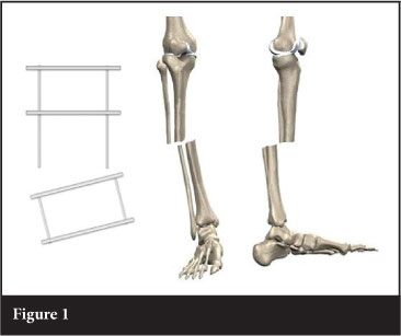
Essential to this technique is constructing a frame with two ring blocks, and the ability to adjust the distance between the ring blocks. When building our trauma frames we incorporate long threaded rods in one of the ring blocks (Figure 1). This allows intra-operative adjustment of the distance between the ring blocks, resulting in inter-fragmentary compression or distraction. During frame application, the frame is set at moderate distraction to facilitate fracture reduction.
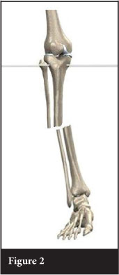
The first few steps of the external fixator application are critical to fracture reduction. This involves application of the proximal and distal reference wires, which are inserted in close proximity to the joint capsules of the knee and ankle respectively. In order to avoid traversing the joint capsules, and eliminating the potential risk of septic arthritis, these wires should be placed outside the reflections of the joint capsules. For the knee and ankle joints, this is approximately 1.5 cm and 1.0 cm respectively.
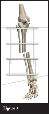
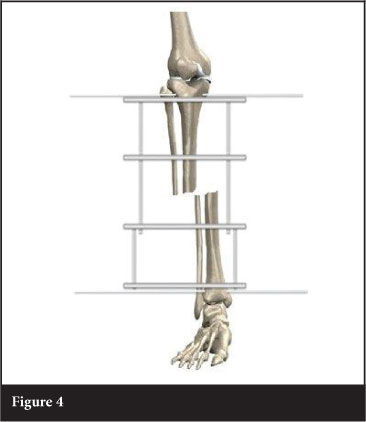
Accurate placement of the reference wires, parallel to the knee and ankle joint lines, will address coronal plane angulation. The proximal reference wire is inserted transverse (in the coronal plane), and parallel to the tibial plateau articular surface / perpendicular to the proximal fragment mechanical axis (Figure 2). The prebuilt frame is applied to the limb, fixed to the wire, and the wire is tensioned. The distal reference wire is then inserted in the coronal plane, and parallel to the distal tibia articular surface / perpendicular to the distal fragment mechanical axis (Figure 3). Attaching and tensioning the distal reference wire to the distal ring will align the proximal and distal fragments in the coronal plane (Figure 4). It is important to ensure proper rotational alignment before attaching the distal reference wire.
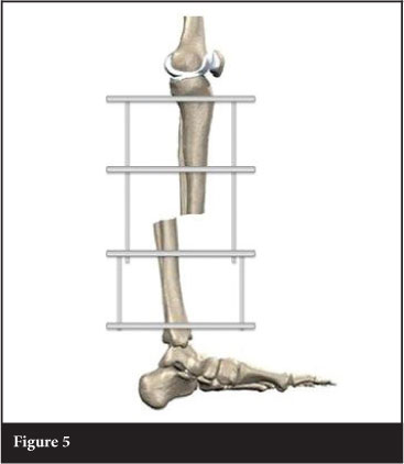
Once coronal plane angulation is corrected, attention must be given to translation and angulation in the sagittal plane. This is addressed by the position in which the distal reference wire is attached to the frame. Due to gravity and patient positioning, the distal fragment will usually be translated posteriorly and angulated in recurvatum (Figure 5). Posterior translation of the distal fragment is corrected by attaching the distal reference wire in the anterior half of the ring and aligned with the knee in the coronal plane (Figure 6).
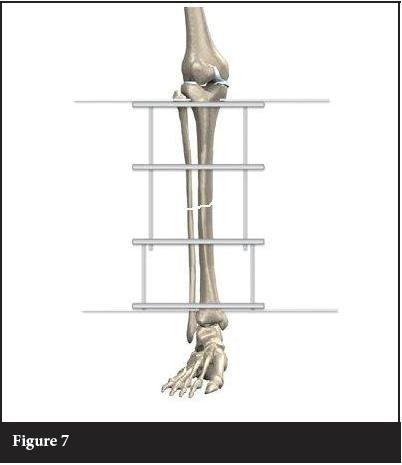
Coronal translation and sagittal angulation are the final displacements to be addressed.
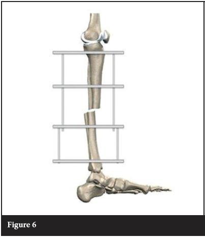
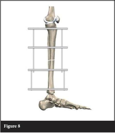
Firstly, coronal translation is corrected by sliding the fracture fragments along the reference wires until aligned (Figure 7). Sagittal angulation (Figure 6) is corrected by rotating the fracture fragments around the reference wires until alignment is restored (Figure 8). Rolled up towels will maintain this reduction until it can be stabilised with fixation to the middle two rings. This final position is maintained by adding fixation to the two middle rings.
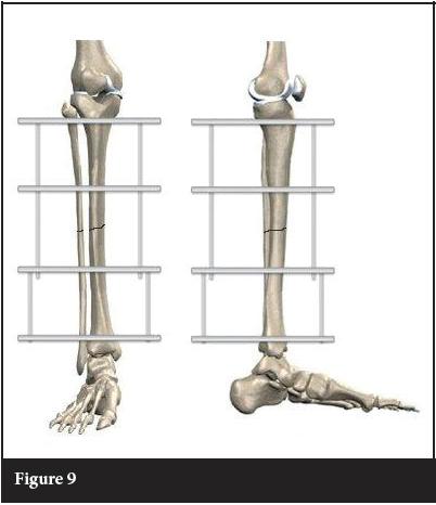
Adding a second, tensioned wire to every ring on the frame completes the fixation. This wire can safely be placed parallel and deep to the anteromedial surface of the tibia (approximately 60° to the horizontal / transverse wire.) The final adjustment of the fixator is compression across the fracture site. This is accomplished by adjusting the distance between the proximal and distal ring blocks (Figure 9).
The most common post-operative complication of circular external fixators is pin tract infection.16,20,21 The first step in preventing pin site infection is a meticulous insertion technique. Wire and pin insertion should be as low energy as possible, with minimum damage to the skin, soft tissue and bone. Following frame application, we advocate dressing pin sites with an alcoholic solution of chlorhexidine-soaked gauze.16,17,22 These dressings are left undisturbed for the first seven days, followed by twice daily cleaning with a chlorhexidine solution.16,17
The first step in preventing pin site infection
is a meticulous insertion technique.
Wire and pin insertion should be as low energy
as possible, with minimum damage to the skin,
soft tissue and bone.
Conclusion
The surgical technique described in this article is simple, reproducible and effective. Accurate reference wires serve as the foundation for a successful frame application. Fracture reduction proceeds in a stepwise fashion, starting with coronal plane angulation and translation, followed by sagittal plane translation and angulation. Finally compression allows for accurate apposition of the fracture fragments. When these steps are followed meticulously it allows the surgeon the ability to obtain anatomical reductions for midshaft tibial fractures.
The content of this article is the sole work of the authors. No benefits of any form have been received or will be received from a commercial party related directly or indirectly to the subject of this article.
References
1. Mullins MM, Davidson AW, Goodier D, Barry M. The biomechanics of wire fixation in the Ilizarov system. Injury, Int J Care Injured. 2003;34:155-157. [ Links ]
2. Fragomen AT, Rozbruch SR. The mechanics of external fixation. HSSJ. 2007;3:13-29. [ Links ]
3. Watson MA, Mathias KJ, Maffulli N. External ring fixators: an overview. Proc Instn Mech Engrs. 2000; 214:45970. [ Links ]
4. Giotakis N, Narayan B. Stability with unilateral external fixation in the tibia. Strat Traum Limb Recon. 2007;2:13-20. [ Links ]
5. Cunningham JL. The biomechanics of fracture fixation. Current Orthopaedics. 2001;15:457-64. [ Links ]
6. Perren SM. Evolution of the internal fixation of long bone fractures. The scientific basis of biological internal fixation: choosing a new balance between stability and biology. J Bone Joint Surg Br. 2002;84(8):1093-10. [ Links ]
7. Hak DJ, Toker S, Yi C, Toresen J. The influence of fracture fixation biomechanics on fracture healing. Orthopaedics. 2010;33(10):752-55. [ Links ]
8. Yamagishi M, Yoshimura Y. The biomechanics of fracture healing. J Bone J Surg. 1955;37(A):1035-68. [ Links ]
9. Paley D. Biomechanics of the Ilizarov external fixator. In Operative Principles of Ilizarov (Eds AB Maiocchi and J Aronson) 1991;33-42. [ Links ]
10. Bronson DG, Samchukov ML, Birch JG, Browne RH, Ashman RB. Stability of external circular fixation: a multi-variable biomechanical analysis. Clin Biomech. 1998;13:441-48. [ Links ]
11. Erhan Y, Oktay B, Lokman K, Nurettin A, Erhan S. Mechanical performance of hybrid Ilizarov external fixator in comparison with Ilizarov circular external fixator. Clin Biomech. 2003;18:518-22. [ Links ]
12. Caja VJ, Kim W, Larsson S, Chao EYS. Comparison of the mechanical performance of three type of external fixators: linear, circular and hybrid. Clin Biomech. 1995;10:401-406. [ Links ]
13. Gasser B, Boman B, Wyder D, et al. Stiffness characteristics of the circular Ilizarov device as opposed to conventional external fixators. J Biomech Eng. 1990;112:15-21. [ Links ]
14. Ilizarov GA. Clinical application of the tension-stress effect for limb lengthening. Clin Orthop. 1990;250:8-26. [ Links ]
15. Roberts CS, Antoci V, Antovi V Jr.,Voor MJ. The effect of transfixion wire crossing angle on the stiffness of fine wire external fixation: A biomechanical study. Injury, Int J Care Injured. 2005;36:1107-1112. [ Links ]
16. Ferreira N, Marais LC. Pin tract sepsis: incidence with the use of circular fixators in a limb reconstruction unit. SA Orthop J. 2012;11(1):10-18. [ Links ]
17. Ferreira N, Marais LC. Prevention and management of external fixator pin track sepsis. Strat Traum Limb Recon. 2012;7:67-72. DOI 10.1007/s11751-012-0139-2. [ Links ]
18. Nayagam S. Safe corridors in external fixation: the lower leg (tibia, fibula, hindfoot and forefoot). Strat Traum Limb Recon. 2007;2:105-10. [ Links ]
19. Antoci V, Voor MJ, Antoci Jr V, Roberts CS. Biomechanical effect of transfixion wire tension on the stiffness of fine wire external fixation. 5th Combined Meeting of the Orthopaedic Research Societies of Canada, USA, Japan and Europe. Poster No: 367. [ Links ]
20. Rogers LC, Bevilacqua NJ, Frykberg RG, Armstrong DG. Predictors of postoperative complications of Ilizarov external ring fixators in the foot and ankle. J Foot Ankle Surg. 2007;46(5):372-75. [ Links ]
21. Bibbo C, Brueggeman J. Prevention and management of complications arising from external fixation pin sites. J Foot Ankle Surg. 2010;49:87-92. [ Links ]
22. Davies R, Holt N, Nayagam S. The care of pin sites with external fixation. J Bone Joint Surg [Br]. 2005;87-B:716-19. [ Links ]
 Reprint requests:
Dr N Ferreira
Department of Orthopaedic Surgery
Greys Hospital
Private bag X9001
Pietermaritzburg 3201
Fax: +27 33 897 3409
Tel: +27 033 897 3299
Email: drferreiran@gmail.com

