


Servicios Personalizados
Articulo
 Inglés (pdf)
 Articulo en XML
 Referencias del artículo
Indicadores

Links relacionados
-
 Citado por Google
 -
 Similares en Google
Compartir

 Permalink
Journal of the South African Institution of Civil Engineering
versión On-line ISSN 2309-8775
versión impresa ISSN 1021-2019
J. S. Afr. Inst. Civ. Eng. vol.65 no.1 Midrand mar. 2023
http://dx.doi.org/10.17159/2309-8775/2023/v65n1a2
TECHNICAL PAPER
Alleviating the problem of cracking of masonry buildings on expansive clay by building flexibility into the masonry
P R Stott; Z Smith; E Theron
ABSTRACT
Damage caused by soils subject to change in volume beneath light structures, particularly low-cost housing units of masonry construction, is unacceptably frequent. It has led to the demolition of many such units within a small fraction of their design lifespan. Perhaps the most spectacular such failure is Lerato Park in Kimberley, where the development was demolished within four years. The reason for this failure is examined in Stott and Theron (2016).
The normal ways of attempting to reduce heave damage have involved increasing the strength and stiffness of foundations, together with reducing masonry panel size through movement joints and increasing the strength of the panels. While these measures have improved the situation somewhat, they are expensive and have proved to be only partially successful. This investigation examines the possibility of increasing the ability of masonry panels themselves to accommodate significant distortion without sustaining unacceptably serious cracking. The existing specifications in SANS 10164 (SANS 10164 2000) are shown to allow considerably greater inherent flexibility than current practice allows. This is dependent on the specified quality of sand (frequently ignored) and water demand requirements, as specified in South African standards, being adhered to.
Keywords: flexibility, expansive soils, light structured houses, masonry buildings, mortar flexibility
INTRODUCTION
Light structures built on expansive clays in South Africa are very prone to cracking for two reasons. Firstly, the expansive potential of clay depends on the suction against which the clay can draw in water. The clay can swell when its suction potential is greater than the pressure of the foundation above it. Normal dwelling houses, and particularly low-cost housing units, apply such low pressures to their foundations that even clays with very limited suction potential can cause heave (Stott 2017). Secondly, masonry as currently used in South Africa is very brittle. Pidgeon (1980) examined design methods for alleviation of heave damage from various countries, including Australia, the USA and South Africa. He noted widely differing values assumed by various methods for the distortions (deflection/length) that masonry can sustain without cracking. Some values were as low as 1 in 360, others as high as 1 in 3 500. He noted that
the lower values are "... unlikely to guarantee a satisfactory level of serviceability ..." (p 287). Currently, in South Africa, 1 in 3 500 is often considered a suitable estimate of distortion for the probable onset of cracking in masonry panels due to soil heave. The reason for the wide range of flexibilities found by Pidgeon is almost certainly due to the mortar specified (and complied with) in the standards of the various countries.
The flexibility of mortar is dependent on several factors, including cement content. It has an inverse, nonlinear relationship to the Portland cement content. Portland cement began to be widely used in mortar in the UK and the USA around 1930. Before that, lime was the key ingredient of mortar for most buildings throughout Europe and America, and many structures in South Africa, including churches, the Union Buildings and the Castle of Good Hope. Lime mortar has high flexibility, but low compressive strength (Costigan & Pavía 2009). Since mortar is applied as a very thin layer between strong units that exercise powerful restraint, failure of mortar by compression is very rare. Compressive strength is of minor importance until high loading is applied. The most important aspects of mortar for the majority of light buildings (up to two storeys) are the ability to bond to the building units (usually bricks or stone blocks) and the ability to keep water out of the building, as per SABS 0164 Part 1 (SANS 1980). Cube compression strength is of very little relevance to these aspects, whereas bond strength and flexibility are crucial.
European Standard EN459 has standards for three strength grades of lime mortar (European Standard 2005).
American Standard ASTM C1489-15 (ASTM 2015) deals with lime putty for structural purposes. Present standards in South Africa do not cover construction using lime mortar, and lime mortar is no longer produced commercially here. However, there is a provision for hydrated lime conforming to SANS 523 (SANS n.d. LEG523) to be used in limited quantities as an additive to cement mortar. There are significant advantages to adding hydrated lime to cement mortar - it greatly improves workability, allowing a greater proportion of sand while increasing the area of adhesion to the bricks, giving better bonding between bricks and mortar. It retains water, allowing improved curing of the cement. SANS 10164 (SANS 10164 2000) notes: "... good results can be obtained with sand of fineness modulus in excess of 2.5 used with the maximum amount of lime as indicated in Table C-1 of Appendix C."
HEAVE DAMAGE
The problem of damage to buildings due to heaving clay became a global problem after the introduction of Portland cement (Costigan & Pavía 2009). Portland cement mortar has the advantages of ease of use and rapid preparation. Until the introduction of cement mortar, apprentice builders had spent much of their apprenticeship learning the complexities of matching lime, and aggregate type and proportions, to foundation conditions. Lime had to be prepared several days before use in construction - necessitating forward planning of building operations. Building with Portland cement mortar requires very little training and far less planning. The convenience and simplicity of using Portland cement mortar rapidly led to it becoming the standard material for masonry construction. Such construction has the disadvantage of being brittle, as it cannot accommodate significant deformation. The addition of hydrated lime (which requires no preparation but provides little intrinsic strength) gives Portland cement mortar much-improved workability and water retention (Tate 2005). This results in a larger area of bonding with the bricks, as explained by Graymont (Graymont.com 2019), and better curing of the cement, resulting in a much-improved bond between bricks and mortar. It also increases the flexibility of the mortar, while reducing its compressive strength. Masonry rarely fails by crushing of bricks or mortar (Sehume et al 2018). The strength characteristic that is meaningful for brickwork is the bond strength between bricks and mortar (Agarwal et al 2021; Gumaste et al 2007; Prasad et al 2014).
SANS 0164-1 7.1.2 C.1 General (SANS 1980) states "... the primary functions of mortar are (a) to provide an even bed so that the load on the wall is distributed evenly over the whole bearing area of the structural units; (b) to bond the structural units together and help them to resist lateral forces; (c) to seal the joints against the penetration of rain. The first requirement for mortar is that it should be readily workable to allow the bricklayer or block layer to produce at an economic rate. It should also be sufficiently resilient to accommodate minor structural movement of the wall or shrinkage or expansion of the structural units, and it should be durable"
Buildings at the former Oranje Hospital (now the Free State Psychiatric Complex) in Bloemfontein provide a very good illustration of the performance of mortar that meets these criteria. The one- and two-storey buildings were built in the late 19th and early 20th centuries. Construction is of baked clay bricks and lime mortar. The underlying foundation material is expansive. These buildings have largely been abandoned, though one or two are still used for storage. The reason for abandonment is failure to meet current standards for hospitals (size of rooms, number, and positioning of ablution facilities, etc). No aprons around the buildings or movement joints in the walls were provided. No maintenance has been performed for several decades, yet the condition of the masonry remains excellent. Despite the length of the building shown in Figure 1, there are no visible cracks or evidence of distress, even though there are no movement joints.
The interior of this abandoned building is shown in Figure 2. It does not show any evidence of cracks forming at the top of the windows or anywhere on the walls after many decades of abandonment and neglect.
A closer look at the outside wall of one of the abandoned buildings in Figure 3 illustrates that there is no evidence of distress found in the mortar and no gaps between the bricks and mortar.
A much later addition of a wall to an abandoned building, to close a gap between two buildings and restrict access to a locked gate, shows typical damage due to soil movement (Figure 4). The new, cement mortar wall, is leaning away from the original wall and typical cracks at the mortar-brick interface are evident. At the end farthest from the old building, severe cracking along mortar joints has taken place. The new wall shows staining and degradation of the mortar, while the old wall shows very little degradation. The original lime mortar allowed the buildings to flex under the action of expansive clay, whereas the later additions do not have the required flexibility to do so.
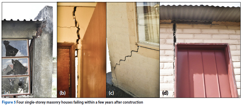
In contrast to these buildings, which have remained intact on unfavourable foundation conditions for about a century, many of the light structures now being built in South Africa have failed to last even five years without severe damage. Figure 5 illustrates four light, single-storey houses that failed within a few years after construction. Picture (a) shows a small light structure in an "emerging middle class" development that became too dangerous to complete before receiving its first coat of paint. The second picture (b) is of a single-storey masonry house in another "emerging middle class" development that lost its structural integrity less than four years after construction. The third picture (c) is of an RDP (Reconstruction and Development Programme) development where almost every house showed evidence of cracks on this scale within five years of construction. In picture (d) the RDP house failed soon after receiving its first coat of paint.
The current philosophy for dealing with this problem in South Africa revolves around building strength and stiffness into foundations, combined with providing movement joints to allow a degree of flexibility in superstructures. Comparing Figures 1 to 4 with Figure 5 suggests that this philosophy might lead to better results if the flexibility of mortar could be increased. The flexibility of mortar is non-linearly and inversely proportional to the compressive strength (Costigan et al 2015). Flexibility increases with increasing sand and hydrated lime content, and decreases with cement content. Flexibility increases as compressive strength decreases. Heave damage increases with a decrease in flexibility.
CURRENT AND RELEVANT RESEARCH IN MASONRY
Most current investigations of masonry performance are concerned with shear and compressive strength. De Villiers et al (2018) modelled compression failure in masonry structures of alternative materials using criteria of cracking-shearing-crushing and compared results with test panels two bricks wide by five bricks high as in EN1052-1 (European Standard 1999) shown in Figure 6. This may have relevance to medium-rise masonry construction, where failure may be due to high structural loading. It may be unhelpful for light structures, such as low-cost housing, where distress in brickwork is usually due to distortion caused by foundation movement rather than by high structural loading.
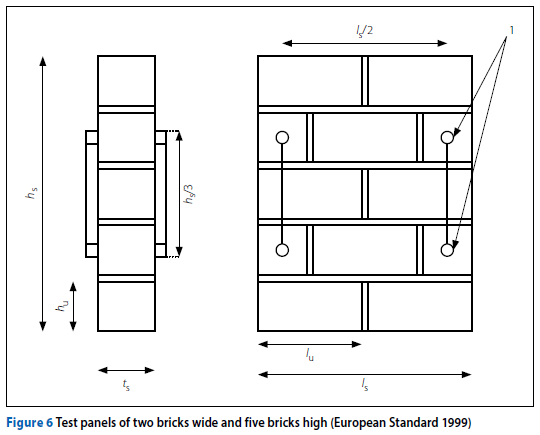
Costigan et al (2015) dealt with both lime mortar and cement-lime mortar. They tested masonry compressive strength, also with two-brick by five-brick panels as in EN1052-1 (European Standard 1999). They found disagreement between mathematical predictions and their experimental results for lime mortar, which they attributed to the significant distortion of the lime during their compressive tests. They noted that, "... the masonry stress-strain relationship becomes increasingly non-linear as mortar strength lowers" The fact that their mathematical models could not cope with the distortion of the lime suggests that lime can accommodate very significant distortion.
McNary and Abrams (1985) dealt only with compression tests, and tested simple stack-bond brick prisms. They found that a softer mortar increases the lateral tensile stress applied to the brick, decreasing the stiffness of the masonry. They also noted that the relationship between stress and strain becomes increasingly nonlinear as mortar strength decreases. These results from four decades ago confirm the findings of recent investigations.
Zucchini and Lourenço (2009) proposed a method of analysing shear walls, and compared their predictions with tests performed by Raijmakers and Vermeltfoort (1992 and 1993, sourced from Zucchini & Lourenço 2009) on panels of 4½ bricks in 18 courses. They pointed out that the analysis is highly nonlinear, and that several advanced computational techniques, such as artificial damping through fictitious viscous forces, are employed to achieve convergence. This leads to some parameters being arbitrarily chosen. Accessibility for normal engineering practice could therefore be problematic. Their analysis might well be suitable for assessing masonry response to deformation by expansive soil, but they only considered the failure of shear walls under high stress.
A general understanding, widespread in the literature, appears to be that the only mortar property of real value is strength.
Samiei et al (2015) regard any variation to their mix designs that reduce strength as being deterioration. Hughes and Taylor (2005) also concentrate on strength properties when dealing with hydraulic lime mortars. This seems to be illogical, since it is well known that hydraulic limes have low strength properties and are used because of their flexibility and durability properties.
CURRENT MORTAR SPECIFICATIONS IN SOUTH AFRICA
Building of most light structures in South Africa is done according to the South African Building Regulations SANS 10400 (SANS 1990) which, for most construction, now calls for Class II mortar that complies with SANS 2001-CM1 (SANS 2001).
Class III mortar, which used to be standard for light masonry construction (SANS 0164 1980, Part 1 (SANS 1980)), appears to have been disregarded in SANS 10400 (SANS 1990). This may be because of the large number of masonry buildings failing due to cracking. A stronger mortar is probably being used to (hopefully) alleviate the problem (Sehume et al 2018). In this paper, we suggest that this change was not helpful, and may lead not only to increased expense but also to worse results for buildings where foundation movement is encountered. The limited classes of mortar allowed in South Africa may explain the discrepancies noted by Pidgeon in his comparisons of design procedures for coping with soil heave in the various countries he considered (Pidgeon 1980).
COMPARISON OF MORTAR SPECIFICATIONS IN AMERICA AND SOUTH AFRICA
Table 1 is from SANS 10164 (SANS 10164 2000), while Table 2 is from ASTM C 270-51T (ASTM 2019).
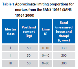
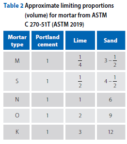
It is not easy to compare Tables 1 and 2 since the American specification deals with volume for all items, whereas the South African specification deals with mass for the cement and volume for the lime and sand. A 50 kg bag of cement packed at the factory has a volume of 33 litres, so to compare mixes, the values of Table 1 have been adjusted accordingly and are shown in Table 3.
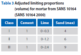
It can be seen that SANS Class 1 is between ASTM Type M and Type S. Class II has close correspondence to Type N. Class III with the maximum permitted quantities of sand and lime has close correspondence to Type O.
The American standard Type K has no South African equivalent. It is unlikely that American practice caters for structures smaller and lighter than RDP housing. This suggests that American practice would probably consider Type K suitable for South African low-cost housing.
SANS Class I mortar is almost irrelevant at present. It is intended for engineering structures such as bridge piers and railway arches, but these are no longer constructed with masonry in South Africa. South Africa no longer produces engineering bricks with the strength to warrant the use of Class I mortar. Class II mortar is suitable for medium-rise buildings (approximately four to seven storeys). The standard of bricklaying in South Africa
is generally so poor at present that most buildings of this kind are now concrete-framed with brick infill panels that do not warrant Class II mortar.
AIMS OF THIS INVESTIGATION
This investigation aims to examine the possibility of building masonry structures to available South African standards, with enough flexibility to allow the design of foundations less stiff and expensive than currently necessary to limit cracking in light economic housing. This will hopefully enable foundation and superstructure to be matched for more economically satisfactory construction. To achieve this aim, a finite element procedure was developed to model the stress in masonry consisting of generic brick units and generic mortar caused by applied distortion.
FINITE ELEMENT ANALYSIS
Development of the finite element model
The finite element analysis was conducted using a PROKON software package that is widely used in South Africa and is accessible to many South African civil and structural engineers. This package is available to the Central University of Technology under an academic licence. While it lacks advanced features which would be useful for the study undertaken - e.g. interface elements and crack propagation - it was considered likely to be capable of giving insight into flexibility, which is the main factor of importance in this investigation. It was considered that, if results from the available program supported the hypothesis that significant flexibility can be provided simply by suitable selection of currently allowable mortar properties, then further investigations, particularly in matching stiffnesses of foundation and superstructure, would probably warrant more advanced software. The analysis did not attempt to deal with crack propagation. It was considered that the horizontal stresses in bricks and adjacent mortar should give a fair approximation of bond stresses, and hence give an indication of the probable onset of cracking. The properties of the material used were as follows:
■ Concrete bricks: Young's modulus of 14 000 MPa and Poisson's ratio of 0.33 (Nichols & Totoev 1997).
■ Mortar Young's modulus:
■ M6 (927 MPa) and CL90 (70 MPa) (Costigan et al 2015)
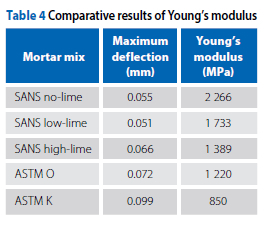
■ Three from the SANS and two from ASTM as per tests detailed in Table 4 (see page 15)
■ Mortar Poisson's ratio 0.2 as per
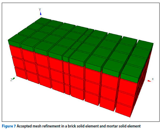
PROKON recommendations. The arrangement of elements was subject to the mesh refinement procedure, until further refinement showed less than 1% influence on stresses within the wall shown in Figure 8. Figure 7 illustrates the accepted mesh refinement in a single brick solid element (red) with a single layer of mortar (green). The standard PROKON conventions for directions, shown in Figure 7, are used throughout. All analyses used PROKON's second order setting for convergence. This setting repeatedly analyses the structure until further increases in deformation are negligible. None of the analyses required more than five iterations.
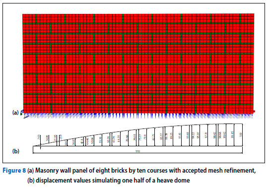
The mesh refinement shown in Figure 7 was applied to a wall panel of eight bricks by ten courses. Figure 8a provides a view of the wall panel designed using PROKON. The wall panel was restrained using restraining conditions XYZxyz (restrained from movement in the XYZ directions and from rotation about XYZ axes) at the first three nodes in line in the Z-direction of the bottom brick solid element. Thereafter, the remaining bottom nodes of the brick and mortar solid elements were restrained in the Y-direction to follow a simulated heave dome. AutoCAD was used to obtain an appropriate heave dome and the displacements were read from the simulated dome. The values presented in Figure 8b show that the maximum displacement was 100, which was converted to 1 mm maximum displacement in the wall. The rest of the dimensions were also divided by 100 and entered in the appropriate displacement table in PROKON. Because the wall panel is symmetrical, a preview of half of the dome is provided ranging from zero displacement found at the corners of the wall panel, to the full 1 mm displacement at the centre of the wall panel.
Evaluating the finite element model
The analysis is concentrated on general flexibility. An indication of bond stresses was assessed as the difference in horizontal stresses between bricks and adjacent mortar elements. Initial analysis used mortar properties found in Costigan et al (2015) and brick properties used later for analysis of experimental panels. Figure 9 shows the results of the finite element analysis of wall panels of eight bricks by ten courses with displacements simulating a heave mound using input parameters corresponding to the mortars of Costigan et al (2015): M6 (Portland cement + hydrated lime) and CL90 (hydraulic lime).
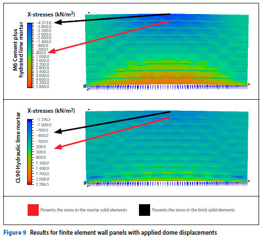
In the heave mound simulation illustrated in Figure 9, tension in the bricks at the top centre of the panel for the M6 wall was about 4 MPa. The stress in the mortar just below the top row of brick elements was approximately 0.4 MPa. The difference in stress is very high and unlikely to be achievable with any feasible bond strength. The CL90 presented a stress of about 0.5 MPa in the middle of the top row of brick elements. The mortar had a stress of approximately 0.3 MPa just below the top row of brick elements. The stresses in the wall panel and the difference in stress between bricks and mortar were far less with the CL90 mortar. Since cracking of light structures usually follows mortar/brick interfaces, this suggests that decreasing mortar strength and stiffness would reduce susceptibility to cracking due to heave distortion. It suggests an explanation for the excellent long-term performance of the buildings in Figures 1 to 4, and the deflection ratio of 1:360 used for design in some countries, noted by Pidgeon (1980) as being ". unlikely to guarantee a satisfactory level of serviceability" (see page 7 of this article). The results showed strong correlation between the increase in flexibility (and reduction of stresses) and decreasing strength of mortar. This suggested that it was worth proceeding with the finite element model and performing tests on physical panels built with a range of mortars feasible for South African practice and South African standards in order to compare theoretical and experimental results.
Available testing equipment was not well suited to modelling a panel on a heave mound. Prevention of failure by instability necessitated restraints, so the experimental panels did not model the response to a heave mound, as the above finite element models did. However, the validity of the finite element model should hold for a range of boundary conditions, and it was considered that a feasible alternative experimental model would be valid for assessing the general validity of the finite element model.
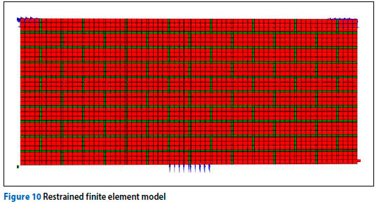
The finite element program PROKON was used to model restrained experimental test panels using the mortar parameters of Costigan et al (2015). This is shown in Figure 10. The restraints at the top corners are linear restraints in the conventional Y and Z directions, while restraints at the bottom corners are linear restraints in the Z direction (see Figure 7). Deformation is applied upwards to the central brick of the bottom of the panel.
Results showed the same trends as found in the preliminary investigation. Stronger mortar (M6 - cement plus hydrated lime) produced less flexible panels. Figure 11 shows the results of the finite element wall panels of eight bricks by ten courses simulating distortion applied in the testing apparatus.
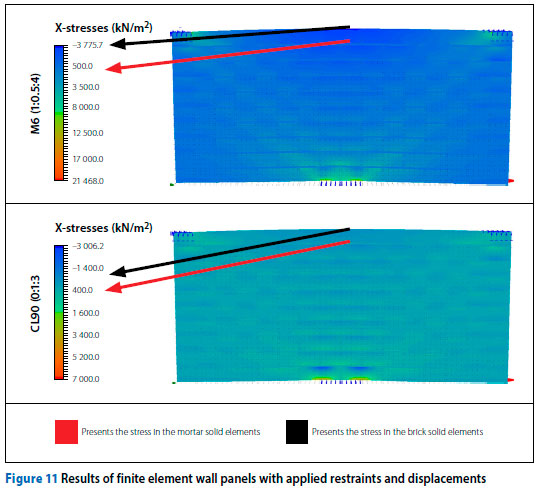
The applied displacements (1 mm) resulted in very different stresses in panels made with a strong, stiff mortar compared to a weaker, more flexible mortar. As can be seen in Figures 9 and 11, stresses throughout the masonry panels decreased considerably as mortar strength decreased and flexibility increased.
In Figure 11 the wall with M6 mortar (cement plus hydrated lime) shows tensile stresses at the upper centre of about 3 MPa and differential stress between bricks and mortar approaching 5 MPa. The wall with CL90 mortar (hydraulic lime) shows tensile stresses at the same location of about 800 kPa and stress difference between bricks and mortar of about 600 kPa. These trends are quite similar to the heave mound results.
It should be noted that, although the analysis does not indicate cracking failure values, it is obvious that the M6 mortar panel would not sustain the applied 1 mm deflection before any feasible bond strength (say 800 kPa compared with the indicated 5 MPa) was exceeded. The CL90 panel shows close to eight times reduction in estimated bond stress for the same deflection, suggesting a much greater likelihood that the applied deformation could be sustained.
MASONRY PANEL TEST APPARATUS
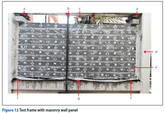
A steel test frame to accommodate an experimental masonry wall panel was used to conduct displacement tests on such panels. To maintain stability, and to provide references for displacements, restraints were applied to prevent vertical and lateral movement of the corners of the panels. A 3 mm steel plate was placed across seven evenly spaced industrial levelling jacks on the lower beam of the test frame. The panel - approximately 1 830 mm x 760 mm, consisting of ten courses of eight standard cement bricks (220 x 98 x 70 mm, 14 MPa) in stretcher bond with mortar thickness 10 mm - was built on top of the steel plate, covered with plastic sheeting, and left to cure for seven days. Figure 12 shows the test frame and an experimental masonry panel ready for testing. Two industrial levelling jacks were placed at the top corners of the experimental wall panel at positions (a) to provide restraint and stability. Safety bars (b) were clamped to the frame and a dial gauge (c) was mounted to the safety bar on the opposite side. The test frame is shown at (d) and the experimental masonry wall panel at (e). The two bottom industrial levelling jacks at the two bottom corners are illustrated at (f) with the fifth levelling jack at (g).
Wall panels were constructed using various mortars to South African and American standards ranging from cement and sand without lime, to cement with high lime and high sand content. Cement/sand/ lime ratios corresponded to:
■ SANS 0164 Class III with 15% less than the maximum allowable quantity of sand, plus no lime, half of the maximum allowable lime and three-quarters of the maximum allowable lime
■ ASTM Type O, which corresponds with SANS 0164 Class III with maximum allowable sand and 20% less than the maximum allowable lime (it, therefore, falls within SANS Class III)
■ ASTM Type K mortar.
RESULTS FOR MATERIALS, TEST PANELS AND FINITE ELEMENT ANALYSIS OF THE TEST PANELS
Material tests
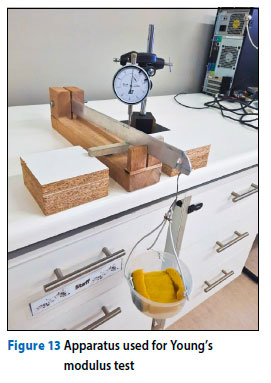
Immediately after construction of the experimental masonry panels, bond-test wallets were built according to SANS 10164 (SANS 10164 2000) using the same mortar. Ten bars of cross-section 10 mm x 12 mm and length 150 mm were cast, using the same mortar, in perspex moulds, for the determination of Young's modulus. One week after construction, the experimental wall panel was tested to failure, the three piers of the nine-brick high wallets were tested for mortar bond strength, and the ten bars of mortar were removed from their moulds for determination of Young's modulus by a bending test.
All Young's modulus samples were subjected to the same loading regime. Mortar beams spanning 130 mm were loaded at the centre of the span. Twenty-four load increments of 14 g were applied at 5-second intervals. The Young's modulus values showed trends as expected. Figure 13 illustrates the setup of the Young's modulus test. This is an existing piece of apparatus, originally designed for a similar test on clay at high suction.
The SANS Class III no-lime mortar mix had the highest Young's modulus, as illustrated in Table 4, and the lowest deflection under the maximum load applied. The other mixes showed the Young's modulus decreasing and deflection increasing with increasing lime and sand content. The ASTM mortar mixes, showed considerable increase in flexibility compared to the SANS mortar mixes. Table 4 shows the results of these tests for the three SANS mortar mixes and the two ASTM mortar mixes.
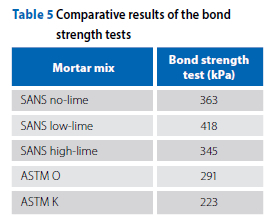
In the masonry bond strength test, the five different mortar mixes were used with standard cement bricks. For the wallets built using the SANS Class III no-lime mortar, the workability of the mix was quite poor, as is usual for no-lime mortar. The SANS Class III low-lime mortar mix allowed better workability resulting in a better bond between the mortar and the brick. The remaining mixes showed a gradual decline in bond strength as the proportion of cement was reduced. It has been noted that results of the standard bond test may be highly dependent on the skill of the bricklayer. On two sites where the requirements of SANS 10164 (SANS 10164 2000) were strictly applied over the duration of a project, a few bricklayers consistently produced excellent bond strength results, a few produced consistently poor results, while most produced acceptable intermediate results. Table 5 shows the results of the bond strength tests for the three SANS mortar mixes and the two ASTM mortar mixes. All test panels and all test wallets were built by the same bricklayer.
Masonry panel tests
After removal of the plastic sheeting surrounding the experimental masonry wall panel, four of the industrial levelling jacks were withdrawn from beneath the wall leaving one jack directly under the centre and two jacks at the lower corners. Two of the jacks from beneath the wall were used at each top corner of the wall to apply restraint. A square tubing safety rail was
clamped to the frame on either side of the test wall as a safety measure. A dial gauge mounted on one of the safety rails measured the vertical deflection at the centre of the wall panel. The central levelling jack was used to slowly raise the bottom centre of the wall panel. The wall and the dial gauge were filmed throughout the jacking procedure. When the dial gauge made a sudden advance, jacking was stopped, and the panel was examined for breakage. Figure 14 (see page 15) provides a view of the wall panels upon initial failure. In the case of the stiffest (no-lime) wall, breakage was immediate and comprehensive; no further jacking took place. In the case of the most flexible walls, breakage was subtle, did not necessarily begin at the top of the wall, and further jacking led to gradual failure eventually reaching the lower courses of bricks.
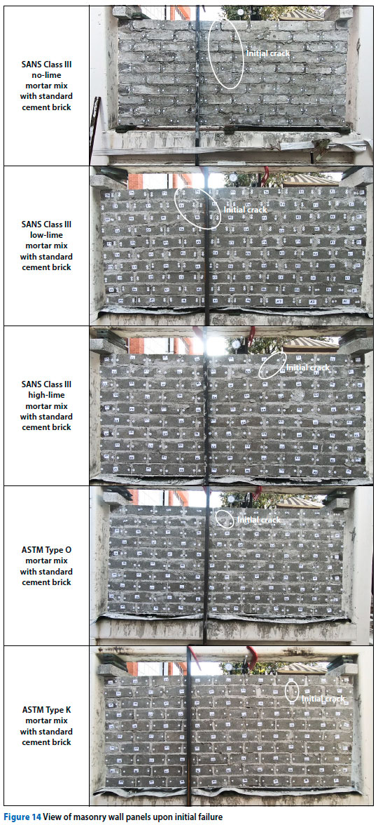
The various walls did not suffer initial failure at the same positions. The panel built using the SANS Class III no-lime mortar mix absorbed the least amount of displacement applied, and failed suddenly
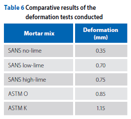
and comprehensively in the middle of the wall, with the failure path going through both bricks and mortar joints. The SANS Class III low-lime wall panel absorbed twice as much deformation as that of the SANS no-lime mortar before failure began. The failure in the SANS low-lime wall panel originated in a mortar joint in the top course of brickwork and moved gradually downwards through vertical and horizontal joints from top to bottom as more distortion was applied. The failure crack became noticeable when dial gauge deflection reached about 1.2 mm. At 1.5 mm displacement, the failure crack was just visible at half-wall height. The Class III high-lime mortar absorbed a little more deformation before the gauge indicated onset of failure. A crack became noticeable at about 1.2 mm applied displacement. The panels using the ASTM mortar mixes absorbed greater deformation before failure was indicated and considerably greater distortion before failure cracking became visible. Both absorbed approximately 4 mm of deformation before the failure crack was visible at half-wall height. Table 6 shows the deformation each wall panel could absorb before initial failure was detected by means of the dial gauge.
Finite element analysis
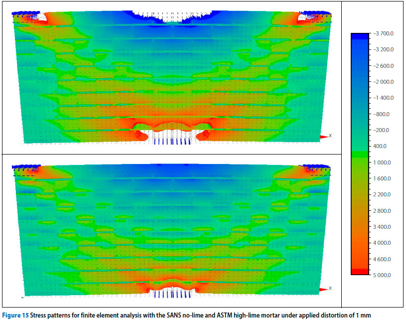
The form of the finite element stress diagrams was similar for all walls with gradually decreasing stress values for the higher lime mortar. The combined stress diagrams of the SANS Class III no-lime mortar and the ASTM Type K mortar are shown in Figure 15. The stress contours cover the stress range 3.7 MPa tension to 5 MPa compression. Stresses outside this range are bleached white. The stresses in the ASTM mortar finite element wall panel are considerably less than in the SANS mortar finite element wall panel deformed by the same applied displacement of 1 mm. The stress reduction is considerably less than that in Figure 11, which shows the difference between Portland cement plus hydraulic lime and hydrated lime with no cement. This suggests that it is unlikely to achieve the flexibility of hydrated lime by mixing cement and hydraulic lime, but it is possible to improve the flexibility considerably. While these diagrams give an indication of the stresses at the applied initial theoretical displacement (1 mm), they fail to indicate the high deformations achieved before cracking became noticeable in the flexible walls, or how gradually the cracks progressed through those walls as deformations increased to very high values. The SANS no-lime wall in Figure 15 comprehensively failed at only one third of this (1 mm) distortion, while the ASTM wall did not even register detectable failure at this same (1 mm) distortion.
PROBLEM TO BE OVERCOME BEFORE ANY SUCH FINDINGS CAN BE IMPLEMENTED
Under SANS 2001 (SANS 2001) the engineer is no longer the authority in deciding on materials and quality as was the case under SANS 1200 (SABS 1983). Rather than follow the advice of the engineer, the principal agent now usually insists on the cheapest mortar available. This usually results in a product generally known as bousand (building sand) being used with only cement and no lime. Our tests on such material, supplied by an NHBRC (National Home Builders Registration Council) inspector from a home building site, showed that it failed the requirements for fines (silt and clay) content and required more than 70% above the permissible amount of water to reach workability adequate for bricklaying to take place. The inspector was surprised and concerned because this is typical of the material used on all the sites inspected. The unacceptable fines content is required to make mortar workable if no lime is used in the mix. This partly accounts for the unacceptable water content. Even a sand of acceptable mortar quality is not likely to reach good workability within the permitted water content without lime. As noted above, SANS 10164 (SANS 10164 2000) recommends sand with a fineness modulus not less than 2.5 and the maximum allowable quantity of lime. Sand of the required quality is available, but suppliers rarely stock such sand, because current practice leads to almost no demand for it.
The use of bousand has not only led to extremely poor standards of masonry, but it has also led to such a drop in demand for building lime that its production has dwindled, and its price has risen sharply. Formerly building lime was available almost everywhere where cement was sold, and at a reasonable price. Today it is sold, but by very few suppliers, and at an unreasonably high price. If engineers and inspectors were to insist on the basic SANS requirements concerning fines content and water demand, this situation could be changed. Unless it is changed there is little likelihood that anything will be done to improve the standard of masonry in South Africa.
DISCUSSION AND CONCLUSIONS
Mortar mix design can lead to a significant change in flexibility and susceptibility to heave damage of masonry. The results of this research project show that the greater the sand and lime content, the more flexible and less crack-prone the resulting masonry is likely to be. Consideration should be given to re-introducing Class III mortar into SANS 10400 (SANS 1990) and NHBRC requirements, as well as introducing a Class IV mortar corresponding to ASTM Type K. This investigation suggests that, adopting ASTM Type K mortar, which calls for 12 parts of sand and 3 parts of building lime for each part of cement, would probably lead to significantly less heave damage to light masonry structures. Using SANS Class III mortar with maximum allowable sand and maximum allowable lime would probably also give very good results. However, unless the existing standards for the sand to be used in mortar are enforced there may be little chance of improvement in the failure statistics for light structures in general and low-cost housing in particular.
It is hoped that the results of this investigation will change perceptions on the cheapness or expensiveness of mortar from the perspective of the overall cost of a building project over an acceptable lifespan. This would allow a rational assessment of the cost savings which might result from using a more flexible mortar to ameliorate the problem of cracking in light masonry construction. This in turn could lead to the possibility of a rational assessment of the performance of foundation and superstructure combined to achieve reliable and economic design.
REFERENCES
Agarwal, D M, Basutkar, S M, Madhavi, K, Devi, M R & Jagadish, KS 2021. Influence of surface reinforcement on the strength of brick masonry wall. Materials Today, 46(10): 5112-5117. [ Links ]
ASTM 2015. ASTM C1489-15. Standard Specification for Lime Putty for Structural Purposes. West Conshohocken: ASTM International. [ Links ]
ASTM 2019. ASTM C270-51T. American Standard Building Code Requirements for Masonry. West Conshohocken: ASTM International. [ Links ]
Costigan, A & Pavía, S 2009. Compressive, flexural and bond strength of brick/lime mortar masonry. In Mazzolani F (Ed). Proceedings of the International Conference on Protection of Historical Constructions (PROHITEC 09). London: Taylor and Francis, pp 1609-1615. [ Links ]
Costigan, A, Pavía, S & Kinnane, O 2015. An experimental evaluation of prediction models for the mechanical behavior of unreinforced, lime-mortar masonry under compression. Journal of Building Engineering, 4: 283-294. [ Links ]
De Villiers, W I, Boshoff, W P & Fourie, J 2018. Numerical modelling of alternative masonry units. Proceedings, International RILEM Symposium on Concrete Modelling (CONMOD18), 26-29 August 2018, Delft, The Netherlands. [ Links ]
European Standard 1999. EN 1052-1 1999. Methods of Test for Masonry. Part 1: Determination of Compressive Strength. Brussels: European Committee for Standardization (CEN). [ Links ]
European Standard 2005. EN 1996-1-1:2. Design of Masonry Structures. Part 1-1. General Rules of Reinforced and Unreinforced Masonry Structures. Brussels: European Committee for Standardization. [ Links ]
Graymont.com 2019. Benefits of cement-lime mortar. Available at: https://www.graymont.com/en/markets/building-construction/mortar/benefits-cement-lime-mortar. [ Links ]
Gumaste, K S, Nanjunda Rao, K S, Venkatarama Reddy, B V & Jagadish, K S 2007. Strength and elasticity of brick masonry prisms and wallettes under compression. Materials and Structures, 40(2): 241-253. [ Links ]
Hughes, J J & Taylor, A K 2005. Compressive and flexural strength testing of brick masonry panels constructed with two contrasting traditionally produced lime mortars. In Proceedings, Repair Mortars for Historic Masonry. International [ Links ]
RILEM Workshop, 26-28 January 2005, Delft, The Netherlands, pp 162-177. [ Links ]
McNary, W S & Abrams, D P 1985. Mechanics of masonry in compression. Journal of Structural Engineering, 111(4): 857-870. [ Links ]
Nichols, J M & Totoev, Y Z 1997. Experimental determination of the dynamic Modulus of Elasticity of masonry units. Proceedings, 11th International Brick and Block Masonry Conference, Shanghai, China. [ Links ]
Pidgeon, J T 1980. A comparison of existing methods for the design of stiffened raft foundations on expansive soil. In Gidigasu, M D, Hammond, A A & Gogo, J A (Eds). Proceedings of the 7th Regional Conference for Africa on Soil Mechanics and Foundation Engineering. Rotterdam: Balkema. [ Links ]
Prasad, R B K, Nasir, O B & Amarnath, K 2014. Size of effect in brick masonry wallets. International Journal of Research in Engineering and Technology, 3(May): 15-18. [ Links ]
Samiei, R R, Daniotti, B, Pelosato, R & Dotelli, G 2015. Properties of cement-lime mortars vs cement mortars containing recycled concrete aggregates. Construction and Building Materials, 84: 84-94. [ Links ]
SABS (South African Bureau of Standards) 1983. G-1200. Concrete (Structural). Pretoria: SABS Standards Division. [ Links ]
SANS (South African National Standard) 1980. SABS 0164: Part 1. Code of Practice for Unreinforced Masonry Walling. Pretoria: SABS Standards Division, p 74. [ Links ]
SANS 10400 1990. Code of Practice for the Application of the National Building Regulations. Pretoria: SABS Standards Division, pp 34-35. [ Links ]
SANS 10164 2000. The Structural Use of Masonry Unreinforced Masonry Walling. Pretoria: SABS Standards Division. [ Links ]
SANS 2001. Part CM1: Masonry Walling. Pretoria: SABS Standards Division. [ Links ]
SANS n.d. LEG523. Law of Data Security and Investigations. Pretoria: SABS. [ Links ]
Sehume, L C, Stott, P R & Theron, E 2018. The influence of mortar mix design on resistance to damage in light structures built on expansive clay. Proceedings, Out-of-the Box 2018 Conference, 24-25 October 2018, Pretoria. [ Links ]
Stott, P R 2017. Identification and assessment of problematic expansive soils. PhD Thesis. Bloemfontein: Central University of Technology. [ Links ]
Stott, P R & Theron, E 2016. Shortcomings in the estimation of clay fraction by hydrometer. Journal of the South African Institution of Civil Engineering, 58(2): 14-24. [ Links ]
Tate, M 2005. The most important property of cement-lime mortar in masonry construction is ... Proceedings, International Building Lime Symposium, 9-11 March 2005, Orlando, FL, pp 1-13. [ Links ]
Zucchini, A & Lourenço, PB 2009. A micro-mechanical homogenisation model for masonry: Application to shear walls. International Journal of Solids and Structures, 46(3-4): 871-886. [ Links ]
 Correspondence:
Philip Stott
Department of Civil Engineering, Central University of Technology
Private Bag X20539, Bloemfontein 9300, South Africa
E: pstott@cut.ac.za / stott.philip@gmail.com
Zandri Smith
Department of Civil Engineering, Central University of Technology
Private Bag X20539, Bloemfontein 9300, South Africa
T: +27 51 507 3911; E: zventer@cut.ac.za
Elizabeth Theron
Department of Civil Engineering, Central University of Technology
Private Bag X20539, Bloemfontein 9300, South Africa
T: +27 51 507 3911; E: etheron@cut.ac.za

DR PHILIP STOTT (Pr Eng, FSAICE) studied civil engineering at Manchester University, obtaining BSc (Honours) and MSc degrees, and subsequently obtained a DEng at the Central University of Technology Free State. He lectured at Ahmadu Bello University, Nigeria, and the University of the Witwatersrand before becoming a consulting engineer. He worked in several fields, including the Southern Perimeter Road in Lesotho; sewage disposal, irrigation and industrial projects; and commercial, educational and residential buildings in Natal, Free State and Northern Cape. In addition he has conducted fire damage assessments and supervised remedial work for commercial structures damaged by fire. He published a number of papers on structural engineering and soil mechanics, and received the Henry Adams and J E Jennings awards.

ZANDRI SMITH (AMSAICE) studied at the Central University of Technology Free State where she obtained her National Diploma (Civil), BTech (Civil), and MEng (Civil). She is a lecturer in structural, transportation and construction materials modules at the same institution. Her research interests includefiniteelementanalysis, construction materials and masonry.

PROF ELIZABETH THERON (Pr Tech Eng, FSAICE), who is an Associate Professor in the Department of Civil Engineering at the Central University of Technology Free State, holds a PhD (Geog) and an MTech Eng (Civil). She is a lecturer and researcher with more than 30 years of academic, industry and research experience. Her research interests include geotechnical and transport engineering. She also serves on the ECSA Council.

