


Services on Demand
Journal

Article
 English (pdf)
 Article in xml format
 Article references
 Send this article by e-mail
Indicators
Related links
-
 Cited by Google
 -
 Similars in Google
Share

 Permalink
R&D Journal
On-line version ISSN 2309-8988Print version ISSN 0257-9669
R&D j. (Matieland, Online) vol.25 Stellenbosch, Cape Town 2009
Development of a Reciprocating Aerofoil Wind Energy Harvester
Russell Phillips; Danie Hattingh
Department of Mechanical Engineering, Nelson Mandela Metropolitan University Port Elizabeth. E-mail: Russell.Phillips@nmmu.ac.za
ABSTRACT
Theoretical predictions and prototype tests investigate the use of a unique type of wind turbine to extract high torque at low rotational speeds. The low solidity ratio combined with large aerofoil area offer potential for improved efficiency over existing low speed wind turbines. Results show favourable efficiencies at tip speed ratios less than 0.5. The high starting and running torque as well as slow rotation render the machine suitable (without the need for gearing) for compressing of air for energy storage systems, water pumping and other high torque applications. The slow speed and quiet operation make the turbine suitable for use in or near residential areas. Control of the aerofoil tails allows seamless turbine power output control from zero to a maximum as well as the ability to fully feather the aerofoils in storm conditions.
Nomenclature
Roman
A aerofoil area (m2)
CL coefficient of lift
Cp power coefficient
D rotor diameter (m)
F total lift force per aerofoil (N)
H component of lift perpendicular to wind (N)
M moment arm of lift force (m)
N rotational speed of rotor (rev/min)
P mechanical power (W)
r turbine radius (m)
U wind speed (m/s)
Vrot velocity vector at aerofoil due to rotation of rotor (m/s)
Vtot resultant of Vrot and U (m/s) W work done (J)
T torque (Nm)
Greek symbols
a angle of attack (deg)
p density of atmospheric air (kg/m3)
θ rotor rotation angle (deg)
Φ lift force direction relative to wind direction (deg)
λ tip speed ratio
1. Introduction
During the past three decades horizontal axis wind turbines (HAWT) have evolved dramatically1 into highly efficient machines capable of extracting up to 45 % (Cp = 0.45) of the kinetic energy of the wind passing through their swept area2 and converting it into electrical energy. Their main purpose is generation of electricity. Their design optimization has been driven by financial pressure to make them as cost effective as possible3 in terms of power output versus capital cost. Most large, modern HAWT's have three slender aerofoils which rotate with a tip speed to wind speed ratio (λ) greater than 51, Aerofoil slenderness held advantages in materials savings and increased efficiency within the constraints of structural strength and aerodynamic flutter.
The Darrieus rotor, a vertical axis wind turbine (VAWT) has also seen commercial use. They have slender aerofoils and are capable of power coefficients4 close to those of HAWT's but suffer from poor starting torque and structural complications. Both the HAWT and Darrieus turbines described are high speed, low torque devices with high λ and low solidity and are well suited to driving electrical generators, often directly coupled5 for efficiency reasons. Little evidence exists of significant research being conducted since the late 19th century1 to optimize slow turning, high torque wind turbines. The American multi-blade wind turbine optimized by Thomas Perry for water pumping is the last record of significant research1. This device is a common sight on South African farms with its numerous curved metal blades arranged in an annular ring. It is characterized by high rotor solidity (80%)1, relatively low 1 (1.9)1, high starting and running torque and a Cp of approximately 0.151. It was never considered efficient enough for electricity generation and hence saw little development after Perry1, Many developing nations have no grid "feed in policy" for wind turbine operators6. Operators therefore can only make use of the electricity that they generate when it is available and cannot sell any surplus generated. If, however, a viable means of energy storage could be developed then the surplus energy could be utilized as and when it was required. Battery storage7 is utilized to a limited extent, however, it is an expensive and seldom viable option. Storage of surplus wind energy harvested is also possible by pumping water to higher elevations and utilizing its energy via hydro turbines8 at a later date. This is obviously limited to areas located near suitable high ground. Compression of air9 is also a possible means of energy storage. The wind turbine requirements for water pumps and compressors are high torque and relatively slow rotation. The American multi-blade wind turbine would therefore be mechanically well suited to the task due to the fact that it could be direct coupled without gearing losses, however, it is possible that a device with similar torque and speed outputs could be developed with improved Cp.
2. Basic Theory
Lift based wind turbines (such as the three described above) produce lift from the flow of air over their aerofoils (which are of suitable cross section)10.
From equation 1 it is evident that an increase in total area would produce a proportional increase in lift force which would increase torque and ultimately power output. (Total area is the product of aerofoil chord length, span and number of aerofoils). It would seem logical that a high solidity ratio (such as the American multi-blade turbine) would yield high output (Cp) however this is not the case. The reason for this was determined by Albert Betz in 19262 and is well explained by quoting Gipe1. "We must strike a balance between a rotor that completely stops the wind and one that allows the wind to pass through unimpeded". Betz demonstrated mathematically that the optimum was reached when the rotor reduced the wind speed by one third. By conserving two thirds of the wind's momentum after passing through the rotor an optimal quantity of the wind passed through the aerofoils rather than being deflected around them. A rotor disc of high solidity would cause most of the wind to pass around it and little energy would be extracted from the wind by the aerofoils. Betz concluded by using a linear momentum theory that the maximum power that could be extracted by a HAWT was 16/27 of the total wind power2. The basis of the wind turbine described in the remainder of this paper is based on one which has the combination of large aerofoil area (due to a large chord length) and low rotor solidity ratio. This is possible due to the fact that the aerofoils face primarily into the wind. An increase in aerofoil chord length results in little increase in solidity ratio. This combination is not possible with any other wind turbines known to be in existence and has the potential of higher power coefficients in comparison to other low λ wind turbines.
3. Principle of Operation
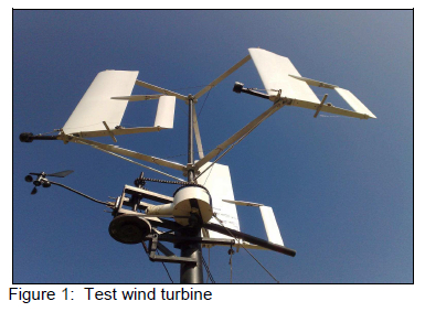
Figure 1 shows the test wind turbine, consisting of three untwisted symmetrical section aerofoils mounted vertically 120° apart on radial arms connected to a central shaft. The aerofoils provided equal lift force in the positive and negative direction due to their symmetrical cross section. The aerofoils were freely pivoted on bearings at each of their spanwise ends, positioned at ¼ chord length (measured from the leading edge). This position was chosen as controlling force on the symmetrical aerofoils would be least if hinged at ¼ chord length11. The aerofoils were each fitted with a tail as shown in figure 2, which would align the aerofoil with the local relative airflow (RAF) automatically.
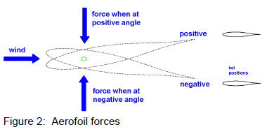
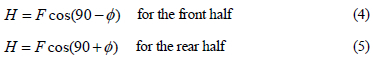
To ensure that the aerofoil tails had a stable restoring tendency once deflected they were hinged at 20 % of their chord length (measured from the leading edge). The aerofoil tails were controlled by a linkage connected to a cam follower. The cam follower ran on a cam fixed to the radial arms of the wind turbine. The shape of the cam was such that when viewed from above the aerofoil tails were made to deflect clockwise in relation to the main aerofoil in the front semi-circle of rotation and anticlockwise in relation to the main aerofoil in the rear semi-circle of rotation. It was found that deflection of the aerofoil tails to approximately 10° in relation to the main aerofoils caused the main aerofoils to deflect to a similar but opposite angle in relation to the relative airflow (RAF).
4. Calculations
The test wind turbine had the following specifications:
□ Aerofoil span 1300 mm
□ Aerofoil chord length 400 mm
□ Turbine radius 840 mm
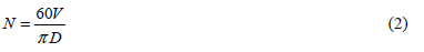
At an assumed wind speed of 16 m/s and with λ = 0.478 the rotational speed would be 89.94 rev/min where:
The peripheral velocity of the aerofoils due to rotation would be 7.65 m/s where:
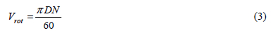
Figure 3 shows the method used to determine the resultant velocity of the RAF over the aerofoil as well as the direction and magnitude of the lift force. Vrot was replaced with velocity components (Vx and Vy) which were summed with U to determine Vtot. Equation 1 was used to calculate the lift force. The lift force was resolved into components. Torque was calculated using the product of the lift force component in the x direction and the effective moment arm:
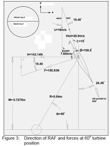
The Torque produced would be the horizontal component of the lift force multiplied by the effective moment arm

The orientation of the aerofoils during a full revolution when running at 87 rev/min and 16 m/s wind speed would be as depicted in figure 4. This was determined using table 1.
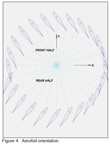
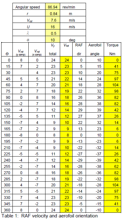
Equations 2-6 were used to calculate the values in table 1.
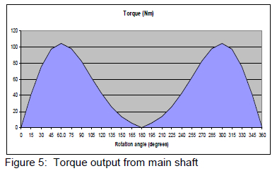
Plotting torque values yielded a symmetrical graph as shown in figure 5.
The work done by the wind turbine was calculated using equation 7.

The area of the graph in figure 6 was equal to the work done per half revolution.
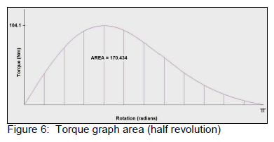
W = (170.434)2
W = 340.86 J
At 86.94 rev/min (1.449 rev/s):
P = 493.9 W
This would be the theoretical power produced by one aerofoil, neglecting aerofoil drag losses as well as wake effects between aerofoils. Due to the low solidity of the device and the low λ the method used should provide a reasonable approximation of power output. The calculations assume that sufficient resisting torque was applied to the output shaft to maintain the chosen speed.
5. Test Results
The test wind turbine shown in figure 1 was tested by mounting it on a moving vehicle and driving the vehicle at various speeds thereby simulating various wind speeds. The tests were conducted during low ambient wind conditions thereby simulating the reduced turbulence that the turbine would experience when mounted on a high mast. The lowest part of the turbine was positioned at a height of 2.3 m above the vehicle to ensure that little or no aerodynamic interference occurred between the vehicle and the turbine. The test setup allowed data to be logged for performance over a wide range of wind speeds in a relatively short space of time. Tests were conducted with three different resistive loads applied to the generator. Figures 7, 8 and 9 display the measured data. Electrical power output was obtained by using the product of the voltage and amperage readings recorded. Wind speed and rotor speed were also recorded. A logging interval of 2 s was used throughout.
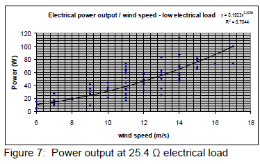
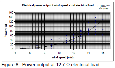
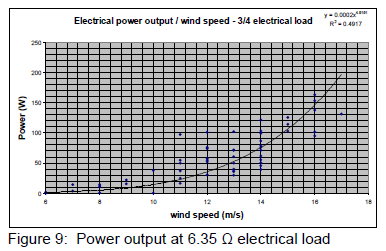
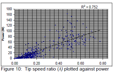
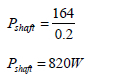
Figure 10 shows the electrical power output plotted against λ. The maximum electrical power13 output of 164W was achieved at λ= 0.478.
The combined efficiency of the mechanical gearing and the electrical generator was determined by removing the turbine from the main shaft and replacing it with a drum. A cord was wrapped around the drum and a steady tension applied by means of a calibrated spring balance. The applied torque was determined using the product of the rope tension and the effective drum radius. The efficiency obtained under conditions which closely matched the 164 W maximum condition was 20 %. Correcting the output power to obtain the actual power in the main shaft:
6. Conclusion
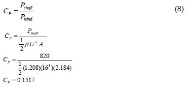
The maximum power coefficient13 achieved during testing in a 16 m/s wind was:
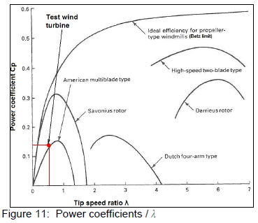
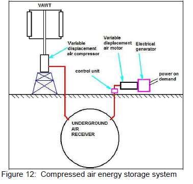
The power coefficients of various types of wind turbines are shown in figure 11 as well as that of the test wind turbine. The performance obtained was very similar to the American multi-blade type but at a lower λ. The potential exists to improve the Cp over that obtained by means of further experimentation and research, particularly with regard to the optimum aerofoil aspect ratio. Figure 12 shows the arrangement of a compressed air energy storage system14 which should be ideally suited to the wind turbine described in this research.
References
1. Gipe P, Wind Power, Chelsea Green, Vermont, USA, 2004.
2. Manwell JF, McGowan JG and Rogers AL, Wind Energy Explained, Wiley, Great Britain, 2002.
3. De Vries E, 49000 MW by 2020: Building offshore in Europe, Renewable Energy World, 11 (1), 2008, 36-42. [ Links ]
4. Gupta R, Biswas A and Shaavona K-K, Comparative study of three-bucket Savonius rotor with a combined three-bucket Savonius three-bladed Darrieus rotor, Renewable Energy, 2008, 33 (9), 1974-1981. [ Links ]
5. Eriksson S, Direct Driven Generators for Vertical Axis Wind Turbines, doctoral thesis, Department of Engineering Sciences, Uppsala University, Sweden, 2008. [ Links ]
6. Winkler H, South African Energy Policies for Sustainable Development, Energy Research Centre, University of Cape Town, 2005.
7. Lin C-C, Lin WB and Chen K-K, A study on integration of hybrid wind/PV/battery renewable energy generation system, proceedings of Energy and Power Systems, 29-31 March 2006, Chang Mai, Thailand, ACTA-Press.
8. Leonhard W, Sustainable Electrical Energy Supply with Wind, Biomass and Pumped Hydro Storage, University Braunschweig, Germany, 2004.
9. Lemofouet S, Hybrid Energy Storage Systems Based on Compressed Air, Swiss Federal Institute of Technology, Switzerland, 2005.
10. Von Doenhoff Abbott IH and AE, Theory of Wing Sections, Dover, New York, 1949.
11. Riblett H, GA Airfoils, Riblett, USA, 1996.
12. Gipe P, Wind Energy Comes of Age, Wiley, New York, 1995.
13. Hughes E, Electrical Technology, Longman, New York, 1981.
14. Yang L, Wang J, Mangan S, Derby JW and Lu N, Mathematical model and energy efficiency analysis of a scroll type air motor, IAENG International Journal of Applied Mathematics, 38, 1, Paper 1, 2008. [ Links ]
Received 29 September 2008
Revised form 6 November 2009
Accepted 22 December 2009
