


Services on Demand
Journal

Article
 English (pdf)
 Article in xml format
 Article references
 Send this article by e-mail
Indicators
Related links
-
 Cited by Google
 -
 Similars in Google
Share

 Permalink
R&D Journal
On-line version ISSN 2309-8988Print version ISSN 0257-9669
R&D j. (Matieland, Online) vol.20 Stellenbosch, Cape Town 2004
Computational Fluid Dynamic Modelling of a Stealthy Air Inlet
A.L. MaraisI; G.D. ThiartII
IM.Sc.(Eng) student, Department of Mechanical Engineering, University of Stellenbosch
IIProfessor, School for Science and Technology, Faculty of Military Science, University of Stellenbosch
ABSTRACT
The aerodynamic performance of a stealthy air inlet design was evaluated using commercial computational fluid dynamics software. The simulations showed that the aerodynamic performance of this type of inlet is adversely affected by the constraints of a stealthy design. Flow separation ahead of the inlet capture plane was identified as one of the major problem areas. It is demonstrated that by modifying the base configuration to alleviate the flow separation problem, it is possible to improve the aerodynamic performance of the inlet. The two designs are compared quantitatively in terms of the kinetic energy correction factor at the engine face, which is a measure of the uniformity of the flow into the engine; significant reduction of this factor is seen to be possible, albeit only in theory.
NOMENCLATURE
Af Engine face area
L Duct length
m Engine mass flow rate
Mx Free stream Mach number (flight Mach number)
Pf Average total pressure at engine face
P∞ Free stream total pressure
V Local velocity magnitude
Vf Average velocity at engine face
Vx Flight speed
V Local velocity vector
χ Distance along duct length
y+ Dimensionless distance from wall
a Kinetic energy correction factor
η Inlet pressure recovery ratio
ρ Density
Introduction
A military aircraft must generally operate unobserved by the enemy for as long as possible if it is to complete its mission successfully. In a modern war theatre, detection risks in the form of advanced radar systems make it increasingly difficult for "normal" aircraft to operate safely. Stealth technology aims to overcome this problem by reducing the radar cross section (RCS), thereby minimising the risk of detection 1,2,3,4.
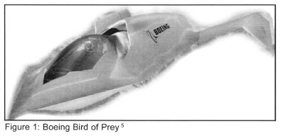
Air inlets are large contributors to the overall RCS of an aircraft. This contribution has to be minimised on a stealth aircraft 1,2,3. Following the suggestions by Paterson 1 a typical stealthy layout consists of a top-mounted inlet (hiding the inlet from ground-based radar) with sharp inlet lips. Sharp leading edges are preferable from a a stealth viewpoint, since rounded leading edges are sources of specular (mirror-like) reflection. The engine is buried inside the airframe, to hide the compressor face, and air is supplied through an S-shaped duct. Such an air inlet configuration is, for example, incorporated in the design of the the Boeing "Bird of Prey" stealth research aircraft5, depicted in Figure 1.
Unfortunately, as a result of the constraints mentioned in the previous paragraph, an air inlet with good stealth characteristics generally has a reduced aerodynamic effciency compared to a similar inlet optimized for aerodynamic performance. The purpose of this paper is to to demonstrate how computational fluid dynamics (CFD) can be utilized to effect and quantify improvements in the aerodynamic performance of a stealth aircraft inlet during the early design stages. This is accomplished by presenting computational results for two configurations: a baseline configuration and a modified configuration. The latter configuration incorporates geometrical modifications that were deemed necessary to alleviate the flow separation observed at the inlet plane of the baseline configuration.
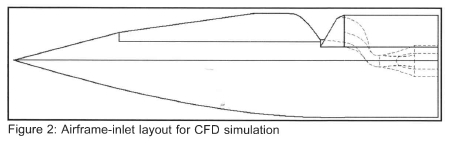
In order to ensure that the flow into an inlet is as uniform as possible, most inlets on military aircraft are either offset from the fuselage or supplied with a boundary layer splitter plate, preventing the fuselage boundary layer from entering the inlet. Both these techniques are undesirable from a stealth viewpoint, since extra edges are added to the planform geometry that can reflect radar energy. For this reason, and also to simplify the computational problem definition, the flow simulations were done without a fuselage boundary layer control system. As a result, the results presented here correspond to a "worst case" flow scenario. The layout of the airframe-inlet combination that were investigated is shown in figure 2. Note that only the front part of the fuselage is shown.
Numerical model
Prior to the simulations reported here, the software1 was validated against a number of external and internal flow problems with known solutions 6. This demonstrated that between 0.5 < M∞ < 0.9, the typical operational envelope of a subsonic stealthy aircraft, a combination of k-z turbulence model, total energy heat transfer model, and the high resolution advection scheme2produced results which most closely matched the known solutions.
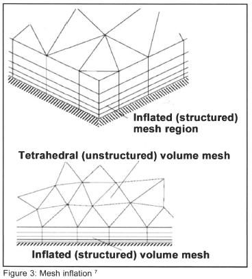
An unstructured volume mesh was created around the air-frame/inlet combination, using the standard meshing tools of CFX 5.5. To ensure that the boundary layer is suffciently resolved when using an unstructured mesh, provision is made to "inflate" the triangular surface mesh into layers of structured prismatic elements normal to the walls, as shown in figure 3. For the purposes of these simulations, 10 layers of mesh inflation were used, with the target position of the first grid node next to the wall being y+ = 11. The total number of elements in the domain were in the order of 6 x10⁵.
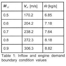
The simulations were run with the airframe at zero angle of attack, and zero yaw angle. Inflow into the domain was through an inlet boundary condition on which the normal speed was specified, and the engine was modelled by specifying the mass flow through an outlet boundary. The engine mass flow is obviously dependent on flight speed; the values used in the simulations are listed in table 1. These values were obtained from the performance curves of the Microturbo TRI-60-5 engine, a small turbojet engine that is often used in air-breathing missiles and unmanned aircraft8. All the remaining external boundaries were modelled as openings with a constant static pressure of 101325Pa and temperature of 288.16 K. Only the steady-state solutions were considered.
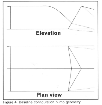
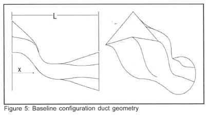
Baseline configuration
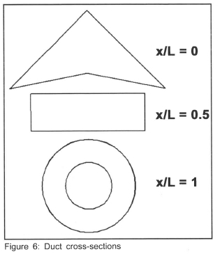
In the baseline configuration the inlet is located behind a "bump"(see figure 4), similar in concept to the inlet-canopy arrangement on the "Bird of Prey". Side and oblique views of the duct leading from inlet to engine are shown in figure 5, illustrating its highly curved shape. Its cross-section also changes from roughly triangular through rectangular to circular (figure 6). Since electromagnetic radiation cannot pass through an opening that is smaller than its wavelength3, this assists in preventing radar energy that may still enter the duct from radiating back out again.
The computational results revealed numerous aerodynamic problems, namely:
1. Strong flow separation at the back of the bump (indicated by "1" in figure 7).
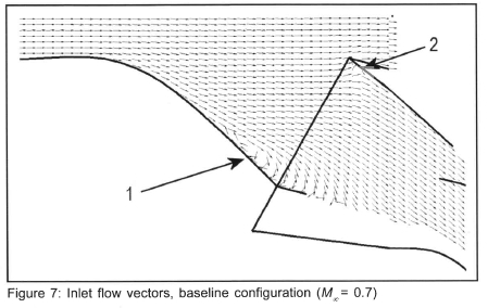
2. Flow spillage (where air enters the duct, but flows out again) over the inlet front lip (indicated by "2" in figure 7). This is partly due to the flow impinging almost normal to the back wall of the duct, causing a higher local pressure inside the inlet lip than just outside.
3. Pronounced non-uniformity in velocity and total pressure profiles around the circumference at the engine face (figure 8).
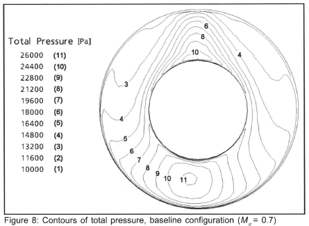
All flight speeds exhibited these problems to a greater or lesser degree than the M∞= 0.7 results presented in figures 7 and 8.
Separation in front of the inlet capture plane reduces the inlet pressure recovery ratio, which is defined as the ratio of the average total pressure at the engine face to the free stream total pressure, i.e.
The inlet pressure recovery ratio is the basic performance parameter of an inlet, and a reduction in its magnitude lowers the effective thrust of the engine, while flow spillage adds to the external drag of the aircraft 9. Non-uniformity of the velocity and total pressure profiles at the engine face translates into a variation in the angle of attack of the engine compressor blades around the circumference. This is unwanted, since too large a distortion in the local inflow velocity and total pressure can lead to stalling of the compressor blades 10.
Modified configuration
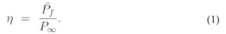
The problems with the baseline configuration prompted a number of detail changes to the design: 1. Attempting to reduce separation in front of the inlet capture plane, the shape of the bump (as seen in the plan view of figure 4) was changed from a constant width profile to a tapering profile (figure 9).
2. The angle of attack of the inlet lips was aligned with the local flow vector, in order to prevent high stagnation pressures inside the inlet, along with the associated flow spillage (figure 9).
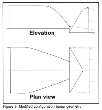
3. The shape of the back wall of the duct, from x/L = 0 to x/L = 0.5, was modified to be more rounded, in the quest for smoother flow acceleration and more uniform velocity and total pressure profiles at the engine face (figure 10).
The cross-sectional shapes of the modified duct at the positions indicated in figure 6 are the same as those for the baseline configuration.
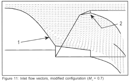
The subsequent flowfield computations revealed that the change in the shape of the bump had negligible influence on the flow separation in front of the inlet capture plane (indicated as "1" in figure 11). The separation bubble is actually slightly bigger both in the 2D plane and in 3D space. The flow spillage was eliminated, but at the cost of a small amount of separation at the top, just inside the inlet lip ("2" in figure 11). The inlet streamtube is displaced by the separation at the back of the bump, causing a misalignment of the flow relative to the inlet lip.
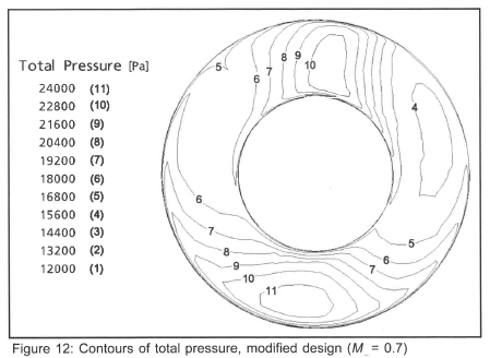
The velocity and total pressure profiles at the engine face is somewhat more uniform (figure 12). It is difficult to judge the level of distortion from the contour plots, however. Quantification of the degree of nonuniformity is pursued in the next section.
Performance comparison
As noted previously, the main performance parameter of an air inlet is the pressure recovery ratio. The numerically determined values of η are plotted in figure 13, for both the baseline and modified configurations. These values are also compared to a theoretical value, determined using the theory of friction loss, developed by Seddon9. This theory assumes that there is no separation on the approach to the inlet or inside the duct, and that all losses in total pressure are entirely due to friction.
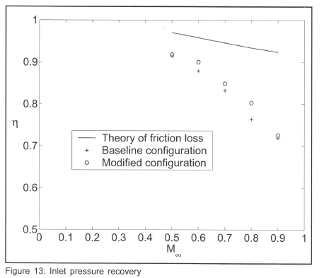
It is clear from figure 13 that the numerically calculated pressure recoveries are significantly lower than the analytical predictions. This is mainly due to the flow separation at the back of the bump, ahead of the inlet capture plane, the effects of which are not considered in the theory of friction loss. When comparing the two numerical solutions, it can be seen that the predicted performance of the modified configuration is slightly better than that of the baseline configuration, especially for 0.6 < M∞< 0.8.
The distortion in the velocity and total pressure profiles at the engine face can be quantified by means of the kinetic energy correction factor 11 on that plane. This factor is defined as
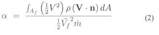
and has a value of unity for a uniform velocity profile. The greater the value of a, the greater the distortion in velocity (and also the distortion in total pressure) at the engine face. Values of a calculated for the two inlet configurations are listed in table 2 as a function of flight Mach number.
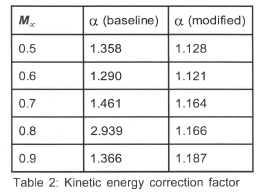
The results presented in table 2 confirm that the distortion is less for the modified configuration than for the baseline configuration throughout the flight speed range. It also shows that for the modified configuration the level of distortion is almost constant throughout the flight speed range as opposed to the highly variable distortion level of the baseline configuration; since inlet distortion lowers the effective surge margin of the engine 10, it seems reasonable to postulate that a more-or-less constant level of distortion across the range of flight speeds is more desirable than a highly variable distortion level. The former situation implies that the surge performance of the engine is more predictable as the aircraft accelerates through its flight speed envelope.
Conclusion
It has been demonstrated that computational fluid dynamics is a useful tool during the conceptual design process of an air inlet, to evaluate competing configurations. Problem areas can be readily identified from the CFD results, which greatly aids in devising modifications to improve the performance of the inlet.
In order to make further progress, it is envisaged that it will be necessary to parameterize the geometry of a typical configuration of inlet and "bump", and then to optimize the configuration in terms of the inlet pressure recovery ratio.
References
1. Paterson J. Measuring Low Observable Technology's Effects on Combat Aircraft Survivability, AIAA-975544, SAE Transactions on Aerospace, 1997, pp. 1515-27
2. Piccirillo Albert C. The Have Blue Technology Demonstrator and Radar Cross Section Reduction. AIAA-965538, SAE Transactions on Aerospace, 1996, pp. 1348-60
3. Aronstein, David C. and Piccirillo, Albert C Have Blue and the F-117A: Evolution of the "Stealth Fighter", American Institute of Aeronautics and Astronautics, 1997
4. Knott E.F. Radar Cross Section, Second Edition, Chapter 7: "Radar Cross Section Reduction", Artech House, 1993
5. Popular Science Website: http://www.popsci.com/popsci/aviation/article/0,12543,365576-3,00.html.l Last acess date: 11/06/2003
6. Marais, A.L. Aerodynamic characteristics of a mission-adaptive stealthy air inlet, M.Sc.(Eng) thesis, University of Stellenbosch, 2003 [ Links ]
7. AEA Technologies, CFX-Build Users manual, Chapter 10, 2002
8. Microturbo Inc. Web Site: http://www.microturbo-usa.com/Products/Turbojet/Tri_60.htm. Last access date: 11/06/2003.
9. Seddon, J. and Goldsmith, E.L. Intake Aerodynamics, Second Edition, Blackwell Science Ltd., 1999
10. Oates, Gordon C. Aircraft Propulsion Systems Technology and Design, AIAA Educational Series, American Institute of Aeronautics and Astronautics, 1989
11. White, F.M. Fluid Mechanics, 3rdedn. McGraw-Hill, 1994
1 CFX 5.5 of ANSYS lnc., Canonsburg, Pennsylvania, USA.
2 CFX 5.5 (and later) allows the user to set a "blend factor" value between 0 and 1, where 0 is equivalent to first-order advection, and 1 enforces full second-order differencing for the advection terms. The high resolution scheme calculates the blend factor locally throughout the flow field. ln flow regions with low variable gradients, the blend factor will be close to one for accuracy, but where the gradients change sharply, it will be closer to 0 to prevent numerical dispersion and maintain robustness .
