


Services on Demand
Journal

Article
 English (pdf)
 Article in xml format
 Article references
 Send this article by e-mail
Indicators
Related links
-
 Cited by Google
 -
 Similars in Google
Share

 Permalink
R&D Journal
On-line version ISSN 2309-8988Print version ISSN 0257-9669
R&D j. (Matieland, Online) vol.19 Stellenbosch, Cape Town 2003
A Correlation for Estimation of Ignition Delay of Dual Fuel Combustion Based on Constant Volume Combustion Vessel Experiments
M. Mbarawa
Senior Lecturer, Department of Mechanical Engineering, Technikon Pretoria, Private Bag X680, Pretoria 0001, South Africa
ABSTRACT
One method of using alternative fuels in diesel engines is by adopting a mixed combustion process called dual-fuelling where alternative fuel such as natural gas (NG) is induced into the cylinder as a primary fuel with air and is subsequently ignited with a pilot injection of diesel fuel. The ignition delay in a dual fuel (DF) engine is different from that in a diesel engine because the primary fuel alters the properties of the charge, reduce oxygen available and undergoes pre-ignition reactions during compression. Various conclusions of DF ignition delay have been reached using different engines. In the present work a constant volume combustion vessel (CVCV) has been used to study the ignition delay of a DF combustion process. Experiments have been performed to investigate the ignition delay period at different initial temperatures and pressures. The results obtained were used to modify the Hu and Milton 's5 DF ignition delay correlation. The proposed correlation predicts a delay period for a wide range of initial temperatures and pressures. The trends exhibited by the correlation are consistent with DF ignition delay engine tests data from other researchers12. In particular, it explains why some reported tests results show that ignition delay is always rising while others show that it decreases temporarily before rising again to very high values. The rising of ignition delay occurs with low pilot diesel quantities and the latter with high ones.
NOMENCLATURE
Alphabetical symbols
Po initial pressure
To initial temperature
minj mass of injected diesel fuel
Greek symbols
τign ignition delay
φgasgas equivalence ratio
Subscripts
oreferring to initial conditions
inj referring to diesel injection ign referring to ignition delay
Introduction
Dual Fuel (DF) engines are modified diesel engines wherein a primary fuel that is normally gaseous is induced along with air and compressed. A small quantity of diesel, called the pilot, is injected near the top dead centre (TDC). The pilot self ignites and becomes the ignition source for the induced charge. Flame propagates from the ignition centres formed by pilot droplets into homogeneous primary fuel-air mixture to complete the combustion process The ignition delay in a DF engine is different from that in a diesel engine because the primary fuel alters the properties of the charge, reduce oxygen available and undergoes pre-ignition reactions during compression. The ignition delay in a DF engine has a significant effect on the combustion, performance and exhaust emissions. A long ignition delay period may result in poor thermal efficiency and high levels of exhaust emissions of hydrocarbons and carbon monoxide and it may be likely to exacerbate knock. For optimum performance, the injection timing in a DF engine has to be set based on the ignition delay. The temperature of the charge, nature of the gaseous fuel and concentration of the gaseous fuel in the charge significantly alter the ignition delay period1,2,3. The induced gaseous fuel also alters the physical properties of the charge being compressed, reduces oxygen concentration and also leads to pre-ignition reactions during the compression process. These factors affect the ignition delay period significantly. The DF ignition delay displays trends different from those observed in the corresponding diesel engines and hence existing diesel engine ignition delay correlations cannot be used for DF mode operation.
Many of previous studies on DF ignition delay have been performed in engines. Nielsen et al1 used a single cylinder diesel engine to study the ignition delay, where it was noted that the ignition delay was significantly increased by the presence of NG. For example it was shown that the presence of 2 % methane in the intake air doubled the ignition delay period. They suggested that part of this delay was caused by a thermal effect; that is introducing the methane into the combustion chamber changed the specific heat of the mixture and thus lowered the compression temperature. Also, it could have been a chemically inhibiting effect of the presence of methane on the diesel fuel reaction rate. However their results didn't firmly verify their hypothesis.
Investigation has been carried out by Liu and Karim2 on factors affecting the ignition delay period of a DF engine. They used a detailed reaction kinetic scheme for the oxidation of the gaseous fuel and employed an experimentally based formula for the ignition delay. They observed that the values of the ignition delay in DF operation strongly depend on the type of gaseous fuel used and its concentrations in the cylinder charge. The associated changes in the charge temperature during compression, pre-ignition energy release, external heat transfer to the surroundings and the contribution of residual gases appear to be the main factors influencing the length of the ignition delay period of the DF engine.
Mtui and Hill4 used multi-cylinders two-stroke diesel engine to investigate the ignition delay of the DF operation. They concluded that with gas/diesel fuelling and appropriate injection timing, ignition delay and combustion duration could be the same as 100% diesel liquid fuelling. Their flame photography and mass-burned determinations indicate that there is no appreciable effect of the presence of the NG on the ignition delay. The timing of the first appearance of the flame does not change significantly if the injection of diesel fuel is stopped. This is in contrast to the findings of Liu and Karim2.
Although there have been numerous attempts to study the ignition delay of DF engines, no suitable correlation is available. It may be due to the fact that most of the previous studies have been carried out in the engines, where their results were hampered by several limitations such as inability to separate a single factor from mutually dependent parameters. Therefore, in order to establish an understanding of the way in which the ignition delay of DF combustion behaves, it is important to employ a single-shot combustion device, which enables to separate a single factor from mutually dependent parameters. A constant volume combustion vessel (CVCV) suits this purpose. CVCV is a device for simulation of the real combustion process by injecting the diesel fuel into a high pressure and temperature air charge mixture.
Several approaches have been used to study the ignition delay period: empirical5,6 and detailed or reduced chemical mechanisms2,7,8. In this work, a purely empirical approach based on the correlation developed by Hu and Milton5 has been selected. In its initial formulation, this correlation is of limited interest because it may be applied for low initial temperatures and pressures only. Hence, the objective of this work is to determine a more general correlation, which could be applicable for a wide range of initial temperatures and pressures conditions existing in naturally aspirated DF engines.
Experimental Apparatus
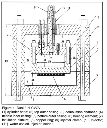
In order to simulate conditions of high temperatures and pressures in engines at top dead centre and to conveniently observe ignition of pre-mixed NG/air mixture by pilot diesel spray, a CVCV was designed. It was electrically heated and was pressurised so that the pre-ignition temperatures and pressures could be obtained in quiescent conditions for its NG/air mixture. Its dimensions were 108 mm bore and 30 mm depth. Figure 1 shows the construction of the CVCV. A single shot diesel injection system was developed from an in-line diesel injection pump giving characteristics identical to those in a diesel engine injection system. The pencil type injector with four holes was mounted centrally and vertically and spray from each orifice oriented with an angle of 15° to the horizontal. The injection pressure and the needle lift signal were measured to determine the injection conditions. Mean temperature and instantaneous pressure in the chamber were measured, respectively, with a thermocouple (type K, 2mm diameter) and a water-cooled piezo-electric transducer (Kistler 5011). Acquisition and processing of these signals were done on a computer. Details of the experimental set-up and the procedures are described in Mbarawa et al9.
Determination of the Ignition delay
The determination of a correlation law allowing the prediction of ignition delay period requires the knowledge of the main parameters influencing the delay. These parameters are experimental conditions in the chamber (i.e. pressure, temperature and the diesel fuel characteristics). Thus, experiments have been carried out over a wide range of temperatures (570 - 690 K), pressures (1.4 - 4.0 MPa), mass of pilot diesel injection (3-57 mg) and NG partial pressures (0.05 MPa to 0.3 MPa) which gives an NG/air equivalence ratio φgas of 0.17-1.8. As it can be seen that the pre-ignition temperatures were a little lower than those normally experienced in diesel engine operation (i.e. 3 MPa, 800 K) as it was found that the higher temperatures could spontaneously ignite the pre-mixed NG-air mixture.
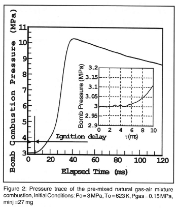
The ignition delay is defined as the period from the start of injection to the time at which ignition occurs. Different concepts of ignition delay have been used in previous studies (pressure rise delay, luminous delay, etc). In this work, the ignition delay is regarded as the pressure rise delay. This was evaluated by recording both needle lift and the dynamic pressure trace of the entire combustion process. The delay section was then enlarged and re-plotted (see Figure 3) such that the pressure rise delay period became distinct from the following combustion process. The pressure that arises from the ignition of the mixture during the delay period is significantly different from the pressure disturbance caused by the pilot diesel injection. By way of example, from Figure 2, the fuel injection (needle lift) was commenced at 0 ms and hence, the ignition delay is evaluated as 5 ms.
Development of the DF ignition delay correlation
The ignition delay was evaluated from the dynamic pressure traces of the combustion process. The ignition delay times of each diesel fuel only and DF combustion experiments at different pre-ignition conditions (i.e. Po, To, minj and φgas for DF combustion) were determined. At first, the diesel fuel ignition delay data were analysed in terms of the relationship between the delay time, pressure, and temperature. Regression analysis was used to develop a diesel fuel ignition delay correlation. The correlation is as follows:
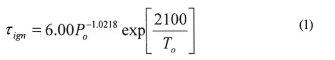
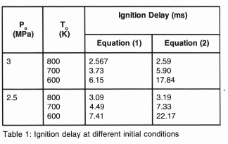
This gives τign values in reasonable agreement with the standard Wolfer6 correlation for diesel combustion, namely:
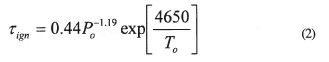
At 3 MPa, 800 K, there is almost an exact agreement, although Equation (1) gives shorter delays at lower temperatures as shown in table 1.
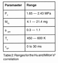
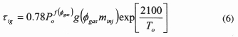
Equation (1) therefore provides a good starting point for a modification of DF ignition delay correlation developed by Hu and Milton5.Their correlation was based on the pre-ignition pressure and temperature experimental data which were below those temperature and pressure of the conventional diesel engine at the point of injection. Using different functional forms of To, Po, φgas and minj, a regression analysis of the experimental data gave an ignition delay correlation, which is applicable to the combustion vessel at delay times less than 30 ms. Above 30 ms delay, the ignition and subsequent combustion were unreliable. Nevertheless, 30 ms corresponds to 108° of crank angle at 600 rpm and is therefore well in excess of that which is applicable in engine operation. The correlation of Hu and Milton5 is as follows:
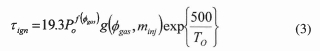
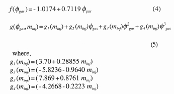
where τign is in ms, Po in bar, minj in mg and To in K. The function f(φgas) and g(φgas, minj) are determined as below:
The ranges where the correlation is applicable are given in Table 2.
In order to modify this correlation other factors such as its relationship with other parameters needs to be considered. For example, as the value of gas-air equivalence ratio (φgas) → 0, the ignition delay value should approach that obtained by a similar correlation for diesel fuel only. Therefore, in order for this correlation to be used in analysing the effect of different parameters (at different ranges) on the DF delay, it needs to be modified for higher temperatures and pressures while retaining its accuracy for low temperatures and pressures.
To modify Equation (3) such that it is consistent with Equation (1), the Arhenius exponential function of the former was held identical to that of the latter. To satisfy the DF effects, the functions f(φgas) and g(φgas, minj) were retained as in Equation (3). Re-examination of the data then gave a new correlation, which fitted DF data almost as well as Equation (3). This is:
Although, the correlation was developed on the basis of the experimental data obtained from the initial temperatures and pressures close to those of the conventional diesel engines at the point of injection, it is expected that this correlation will differ from normal correlation for engine. This is due to the fact that first, the strong in-cylinder turbulence generated in many engines cannot be achieved in a combustion vessel. Secondly, the combustion vessel gas temperature is necessarily decreasing before auto-ignition whereas if the injection event occurs during the compression stroke of an engine, the temperature is increasing.
Comparison of calculation and experiment of DF ignition delay at different initial conditions
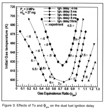
Figure 3 shows the comparison of the experiment and correlation results. It can be seen that the modified correlation shows a reasonable agreement with experimental ignition delay (tign = 6 ms). It can also be seen that the correlation demonstrates that the ignition delay period reaches a certain minimum value at a particular fgas. From that point, increasing or decreasing fgas prolongs ignition delay as shown in Figure 4.
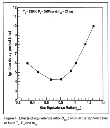
This behaviour is well documented in previous investigations1,2. The effect of the air charge temperature has a strong influence on the delay period. As the temperature increases, ignition delay also decreases due to the increase of pre-ignition chemical reactions which are commonly regarded as the first stage ignition (cool flame). Although the correlation has not considered many factors like mixing, wall temperature, etc., it gives fairly accurate trends.
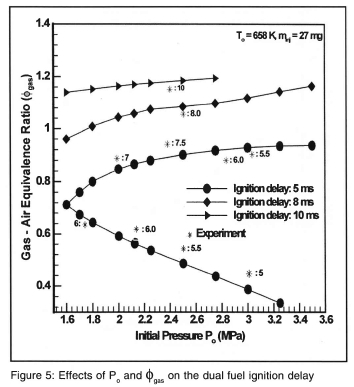
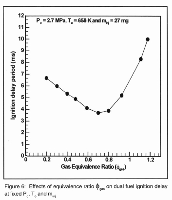
Figure 5 shows that the ignition delay at fixed conditions of To and minj decreases to a certain minimum value at a particular φgas. From that point, increasing or decreasing φgas prolongs ignition delay as shown clearly in Figure 6.
Simulation Results
Effects of the Initial conditions (φo, minj) on the DF ignition delay
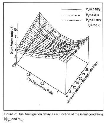
Figure 7 shows the contour plot of the ignition delay variation with the φo and minj at fixed temperature and pressure. The 3-D contour plot shows that the combined effect of φgas and minj is complex. Increasing the value φgas from the minimum of 0.4 gives a consistent lengthening of the delay only for low pilot injection quantities (approximately 4 mg). As the pilot diesel fuel is increased on the constant minj line, the ignition delay contour first reduces with increasing φgas before commencing to rise. This can be clearly seen for minj of 28 mg where the minimum delay occurs at φgas of about 0.7. That is, the contour valley moves progressively to higher φgas and minj. This is a possible explanation for different observations made in previous reports. Further experiments are needed to clarify this question in equipment which can be extended to higher initial temperatures and pressures.
Effects of the Initial conditions (Po, minj) on the DF ignition delay.
The 3-D contour plot indicates the complex combined effect of Po and minj on the ignition delay. It can be seen in the figure 8 that, for the case φgas = 0.5, as the initial pressure Po is increased, the τign contour on the constant minj line decreases.
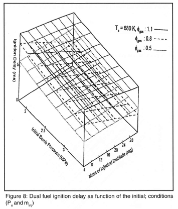
It also increases as pilot diesel fuel increases on the constant pressure line. In the other two cases (i.e., φgas = 0.8 and φgas = 1.1), τign decreases as the pressure Po increases on the constant minj line. It also decreases on the constant pressure line as the mass of pilot distillate increases.
Effects of the Initial conditions (To, minj) on the DF ignition delay.
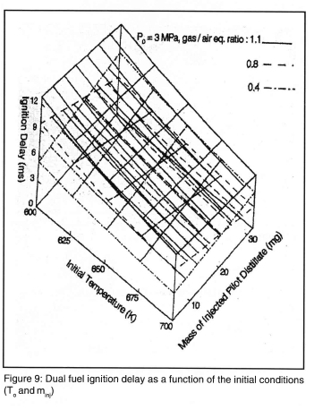
Figure 9 shows the 3-D contour plot of the combined effect of T0 and minj on the ignition delay. For the case of φgas = 0.4, as the initial value of T0 is increased, τign period on the constant minj line decreases but it increases on the constant temperature line as the pilot distillate increases. In the other case (i.e., φgas = 0.8 and φgas =1.1), τign decreases as the temperature To increases on the constant minj line but in the other direction of the contour plot on the constant temperature line τign decreases as the mass of pilot diesel injection increases.
Conclusions
Based on the present work the following conclusions are drawn:
□ Experiments have been carried out in CVCV to obtain the data for the study of the ignition delay of the DF combustion process. The data were used to modify a DF ignition delay correlation proposed for low initial temperatures and pressures
□ A modified ignition delay correlation has been used to investigate the effects of the initial pressures and temperatures on the ignition delay period of the DF combustion process.
□ The trends exhibited by the correlation are consistent with known data from engine tests from other researhers1,2. In particular, it explains why some engine tests show that ignition delay always rising while others show it decreasing temporarily before rising again to very high values. The former occurs with low pilot injected diesel quantities and the latter with high ones.
References
1. Nielsen O B et al. Ignition Delay in the Dual-fuel Engine. SAE Paper 870589, 1987.
2. Liu Zand Karim G A. The ignition Delay Period in Dual Fuel Engines. SAE Paper 950466, 1995.
3. Karim G A. Ignition of Premixed Fuel and air Charge by Pilot Fuel Spray Injection with Reference to Duel Fuel Combustion. SAE Paper 680768,1968.
4. Mtui P L & Hill G P. Ignition Delay and Combustion Duration With Natural Gas Fuelling of Diesel Engines. SAE Paper 961933, 1996.
5. Hu B and Milton BE. A Correlation for the Ignition Delay of Dual-fuel Combustion Based on Constant Volume Combustion Bomb Experiments. Int. Conf. on Fluid Eng., JSME Centennial Grand Conf, Tokyo, pp 1997.
6. WolferH. IgnitionLag in Diesel Engines VDI-Forchungsheft 392, 1938, (English Translation, RAE Farnborough, Lib. No 359, UDC 621-436 - 047, 1959).
7. Halstead M P et al. A Mathematical Model for Hydrocarbon Autoignition at High pressures. Proc. R. Soc. Lond. Ser. A, Vol. 346, pp. 515-538, 1975. [ Links ]
8. Westbrook, C. K. & Dryer, F. L., Chemical Kinetic Modelling of Hydrocarbon Combustion. Prog. Combust. Sci., Vol. 10, pp 1-57, 1984. [ Links ]
9. Mbarawa M, et al. Fuel injection characteristics of diesel stimulated natural gas combustion. Int. Journal of Energy Research, 23, pp. 1359-1371, 1999. [ Links ]
