


Serviços Personalizados
Artigo
 Inglês (pdf)
 Artigo em XML
 Referências do artigo
Indicadores

Links relacionados
-
 Citado por Google
 -
 Similares em Google
Compartilhar

 Permalink
South African Computer Journal
versão On-line ISSN 2313-7835
versão impressa ISSN 1015-7999
SACJ vol.29 no.3 Grahamstown 2017
http://dx.doi.org/10.18489/sacj.v29i3.452
RESEARCH ARTICLE
A state-of-the-art survey of indoor positioning and navigation systems and technologies
Wilson SakpereI; Michael Adeyeye-OshinII; Nhlanhla B.W. MlitwaIII
IUniversity of Bologna, Italy. wilson.sakpere2@unibo.it
IISheridan College, Western Australia, Australia. madeyeye@sheridan.edu.au
IIIUniversity of Zululand, Richards Bay, South Africa. mlitwan@unizulu.ac.za
ABSTRACT
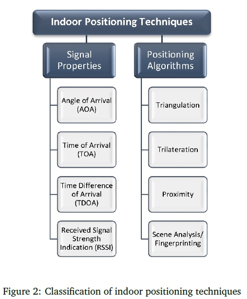
The research and use of positioning and navigation technologies outdoors has seen a steady and exponential growth. Based on this success, there have been attempts to implement these technologies indoors, leading to numerous studies. Most of the algorithms, techniques and technologies used have been implemented outdoors. However, how they fare indoors is different altogether. Thus, several technologies have been proposed and implemented to improve positioning and navigation indoors. Among them are Infrared (IR), Ultrasound, Audible Sound, Magnetic, Optical and Vision, Radio Frequency (RF), Visible Light, Pedestrian Dead Reckoning (PDR)/Inertial Navigation System (INS) and Hybrid. The RF technologies include Bluetooth, Ultra-wideband (UWB), Wireless Sensor Network (WSN), Wireless Local Area Network (WLAN), Radio-Frequency Identification (RFID) and Near Field Communication (NFC). In addition, positioning techniques applied in indoor positioning systems include the signal properties and positioning algorithms. The prevalent signal properties are Angle of Arrival (AOA), Time of Arrival (TOA), Time Difference of Arrival (TDOA) and Received Signal Strength Indication (RSSI), while the positioning algorithms are Triangulation, Trilateration, Proximity and Scene Analysis/ Fingerprinting. This paper presents a state-of-the-art survey of indoor positioning and navigation systems and technologies, and their use in various scenarios. It analyses distinct positioning technology metrics such as accuracy, complexity, cost, privacy, scalability and usability. This paper has profound implications for future studies of positioning and navigation.
Keywords: Indoor Environments, Indoor Navigation, Indoor Positioning, Localisation, Pedestrian Navigation, Positioning Techniques, Sensors, Wayfinding
1 INTRODUCTION
The adoption and use of the mobile device has made computing more mobile, ubiquitous, robust and context-aware (Aker & Mbiti, 2010; Reddy et al., 2010). The mobile phone is the most popular and widely used mobile device in this information age (Goggin, 2012; Dinh, Lee, Niyato, & Ping, 2013). By comparing it with contemporary analogue phones possessing limited audio exchange functionality in fixed locations, it was discovered that multi-functional mobile phones, known as 'smartphones', are fast becoming irreplaceable devices (Reddy et al., 2010; Goggin, 2012; Dinh et al., 2013). However, these mobile devices can only function effectively within an ideal situation and environment (Aijaz, Aghvami, & Amani, 2013). For instance, communicating through voice and textual means is dependent on the availability of the network (Aker & Mbiti, 2010; Dinh et al., 2013). In addition, accessing learning environments online and downloading useful applications are dependent on network or Wi-Fi availability.
Likewise, using a mobile phone to navigate in an outdoor environment is dependent on uninterrupted access to satellite signals and network or Wi-Fi availability. In buildings where network or Wi-Fi availability is almost non-existent, users will find it difficult to do much on the mobile device (Aijaz et al., 2013). Such difficulties are mainly encountered in indoor environments, basements and underground environments of large buildings. These difficulties make internet access and the use of certain applications challenging. Hence, the mobility and ubiquity of the mobile device has made it a popular personal device, which has many uses including navigation (also known as Wayfinding). Navigation in indoor environments, which is the focus of this study, has become as popular as outdoor navigation.
In effect, there has been a steady and exponential growth in the research and use of positioning (also known as localisation) and navigation technology outdoors in recent years. As a result, attempts to implement these technologies indoors have led to numerous studies in this field, spurring researchers into discovering ways to make life easier for people while navigating indoor spaces. These works employed techniques and technologies which have varied levels of strengths, as well as weaknesses. The outcomes of this research have resulted in observed inhibitions in the various technologies which have affected performance.
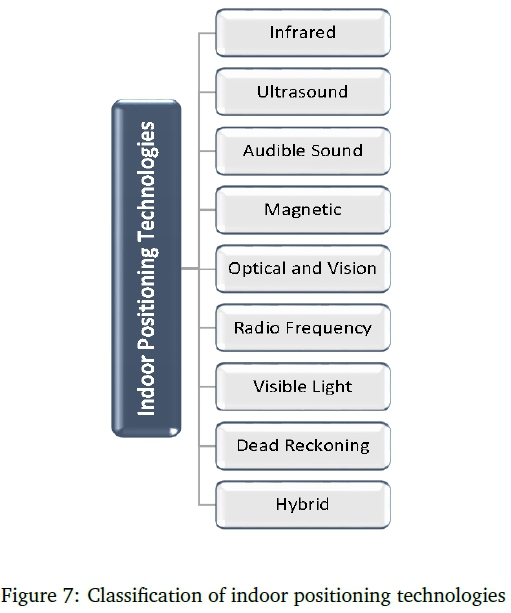
Although these technologies were discussed in a previous study by Sakpere and Adeyeye (2015), an extensive state-of-the-art survey of these technologies in indoor navigation and their use in various scenarios and environments is presented in this paper. The existing technologies, observed from literature, used in positioning and navigation studies include Infrared (IR), Ultrasound/Ultrasonic, Audible Sound, Magnetic, Optical and Vision, Radio Frequency (RF), Visible Light, Pedestrian Dead Reckoning (PDR)/Inertial Navigation System (INS) and Hybrid. The RF technologies include Bluetooth, Ultra-wideband (UWB), Wireless Sensor Network (WSN), Wireless Local Area Network (WLAN), Radio-Frequency Identification (RFID) and Near Field Communication (NFC). Expectedly, as technology advances we are likely to witness newer technologies being used in similar studies.
In addition, the positioning techniques applied in indoor positioning systems and technologies include the signal properties and positioning algorithms. The prevalent signal properties are Angle of Arrival (AOA), Time of Arrival (TOA), Time Difference of Arrival (TDOA) and Received Signal Strength Indication (RSSI), while the positioning algorithms are Triangulation, Trilateration, Proximity and Scene Analysis/ Fingerprinting. However, because there maybe numerous positioning techniques and technologies, only those innovations that are most relevant to the purpose of this survey have been discussed. The strengths of these techniques and technologies as well as the areas of weaknesses and non-performance are noted and discussed. How the techniques and technologies fare against one another is compared and discussed.
The focus, therefore, is on the application of techniques, algorithms and methods in indoor positioning and navigation scenarios by researchers in this field. This is meant to provide an understanding of present research stages, and propose possible research directions for further improvement. Hence, this survey made use of over 180 articles in journals, conference proceedings, books, book chapters, dissertations, and online articles or white papers to get an academic and industry view of the current state of the research. The literature search was done using flagship digital libraries. Only articles within the scope of this survey based on the study carried out in the articles were considered to be relevant. The survey follows a historical and systematic approach in its presentation. The indoor positioning techniques and technologies were discussed based on their classification or types, features, application scenarios, strengths and limitations.
Figure 1 shows a flow diagram of the discussion's structure.
The remainder of the paper is structured as follows: Section 2 introduces the concept of Navigation from a general point of view and narrows it down to the subject of discussion in this survey; Section 3 examines the various positioning techniques that have been used to determine position optimally while Section 4 discusses the positioning technologies and the techniques applied in them; Section 5 identifies further research directions and Section 6 presents the conclusions of this survey. Moving forward, we now examine navigation in detail.
2 NAVIGATION
The word navigation has its root in Latin and is derived from the words 'navis' meaning ship and 'agere' meaning to drive, move or direct (Sonnenberg, 1988; Hofmann-Wellenhof, Legat, & Wieser, 2011). The definition of navigation is as diverse as its activity. For example, Sonnenberg (1988) and Hofmann-Wellenhof et al. (2011) defined navigation in relation to vehicles or objects and not humans, while Prasad and Ruggieri (2005) and Kaplan and Hegarty (2006) took into account that humans and objects can be involved in the navigation process. However, certain points are common to all these definitions of navigation. They are: determination of the initial position or departure point of the object or person, knowledge of the destination point of the object or person, and the information necessary to determine the best path or route from the initial position to the destination. These three points are the major determinants in navigation that must be taken into consideration before orientation may begin (Sakpere & Adeyeye, 2015). They help the traveller in arriving at the destination, and on time.
For this survey, navigation will be defined as the process of successful orientation by a human, object or vehicle from a point of departure through a pre-determined and well-planned path or route to a desired or known destination in outdoor, indoor and even more challenged spaces without inhibitions or quality-loss.
2.1 Outdoor navigation
In the general sense, navigation is an activity that dates back to as far as humans have been in existence (Prasad & Ruggieri, 2005; Grewal, Weill, & Andrews, 2007). Originally, navigation was used to describe the movement of ships on sea (Prasad & Ruggieri, 2005). In modern times, it has included much more such as human, car, robot, airplane and spaceship navigation. The goal of navigation is to move from an initial position through a pre-determined path or route to a destination successfully.
Early humans used natural landmarks and celestial elements like wind, mountains, trees, sun, moon and stars as guide while navigating on land and sea (Titterton & Weston, 2004). These elements helped them to calculate and determine their movement eastwards, westwards, southwards or northwards. Travelling on sea was a major means of navigation in ancient times. In the 15th century, Christopher Columbus did his explorations by travelling mainly on sea using celestial elements and navigation maps and tools (Prasad & Ruggieri, 2005; World Book Inc., 2013). The use of maps and charts evolved from celestial elements when people began to draw landmarks to keep detailed records for directions (Prasad & Ruggieri, 2005; Titterton & Weston, 2004). Over time, tools that helped in achieving a more accurate navigation timing were developed. They include the hourglass, cross-staff, astrolabe, sextant, quadrant and compass among others (World Book Inc., 2013). The use of these tools evolved as the methods of navigation evolved.
The introduction of air navigation brought new challenges with it (Hofmann-Wellenhof et al., 2011). Locating a position in the air was more difficult than on land, which could lead to an aircraft getting lost (Prasad & Ruggieri, 2005). Thus, inventors developed tools that made positioning and navigation faster and more accurate (Hofmann-Wellenhof et al., 2011; Powers & Parkinson, 2010). Such tools include the compass, crystal oscillator for radio navigation, dead-reckoning processes (used also in INS) and automated positioning systems (Ibid.). However, these ancient methods of navigation had their difficulties (Hofmann-Wellenhof et al., 2011). Positioning and navigation was not accurate and easy to use. It involved a lot of guesswork resulting in complexities and sometimes failure such as losing one's way. For example, Christopher Columbus made an error during one of his explorations when he got to the Americas; he thought he had arrived in Asia and named the place the Indies (Prasad & Ruggieri, 2005; World Book Inc., 2013). In addition, the orientation to a destination takes time since there is no certainty of the exact navigation route (Prasad & Ruggieri, 2005).
Advancements taking place in marine and land navigation led researchers to work on navigating in space (Prasad & Ruggieri, 2005). Navigating in space has its own challenges with respect to positioning and navigation. However, the possibilities of traveling in space inspired researchers (Ibid.). These researchers attempted varied approaches to determine positions on the Earth using orbiting satellites (Pace et al., 1995; Whitlock & McCaskill, 2009). Successes recorded led to the development of the Global Positioning System (GPS), which is eventually used in many new applications including outdoor positioning and navigation (Grewal et al., 2007; Hofmann-Wellenhof, Lichtenegger, & Collins, 2012). With traffic road signs and billboards as conventional means of navigating outdoors, locating a destination, and helping a user understand current position on the route of orientation, the advent of the GPS has transformed navigation into a simplified activity. Users have the choice of using conventional and/or technological means of navigation.
Areas of application of the GPS include land, marine, air and space (Sonnenberg, 1988, p.42). Hofmann-Wellenhof et al. (2011, p. 375) stated some specific areas of navigation applications. They include location-based services (integrating navigation with communication and information), mobile robotics (complementing navigation with computer science and mechanical engineering), mobile mapping (combining navigation with imaging and geo-referencing), pedestrian navigation (mainly user-focused) and indoor navigation (focused on highly demanding indoor environments). The GPS may be integrated in these application areas. GPS is mainly used for tracking, timing and positioning of which navigation is a part (Whitlock & McCaskill, 2009).
Furthermore, because position determination is a major problem in a wide range of positioning and navigation applications and systems, the GPS has been widely adopted for outdoor use due to its accuracy, precision and effectiveness (Ibid.). However, there is no such acceptance with indoor positioning and navigation systems (Van-Diggelen, 2009). This is due to buildings and walls that serve as obstacle to the satellite's signals.
2.2 Indoor navigation
Following the numerous success of the GPS outdoors, the challenge was shifted to the provision of such services for the indoor environment (Mautz, 2012). Indoor navigation has generated interest in users and researchers, shifting position computation from outdoors to indoor spaces. Thus, several applications have been developed to aid indoor services. Mautz (2012, p. 7) points out that, "the ability to locate objects and people indoors remains a substantial challenge, forming the major bottleneck preventing seamless positioning in all environments." Thus, navigating indoors with mobile devices became an interesting subject in recent years.
Indoor navigation is a subject that has been studied over the years using variety of techniques and technologies (Storms, Shockley, & Raquet, 2010; Hammadi, Hebsi, Zemerly, & Ng, 2012)Gu, Lo, and Niemegeers (2009) posit that an indoor navigation system consists of a network of devices used in locating objects or people inside a building. Upon knowing where something or someone is, activities such as tracking and position determination can be done with the information (Gu et al., 2009; H. Liu, Darabi, Banerjee, & Liu, 2007). The early indoor navigation systems involved using sensors, which consist of transmitters and receivers, for tracking and positioning (Want, Hopper, Falcäo, & Gibbons, 1992; Fukuju, Minami, Morikawa, & Aoyama, 2003; Minami et al., 2004). Either of the transmitters or receivers could be fixed while the other is on the user who is in motion. Similarly, recent indoor navigation systems use mobile phones for positioning and navigation (K. Liu, Liu, & Li, 2013; Barberis, Bottino, Malnati, & Montuschi, 2014).
Over the past decade, mobile phones have been used in indoor navigation research (Hammadi et al., 2012). Mobile indoor navigation involves an individual finding his/her way around within indoor spaces to arrive at a desired destination using an interactive navigation system in a mobile device (Hammadi et al., 2012). It involves the use of a mobile device, an installed navigation application in the mobile device, map of the indoor space of the building and a database to store map data. Navigating in large buildings, such as museums, airports, malls, hospitals and campuses, with an indoor navigation system guides a user to a preferred destination without hassles and without wasting time. However, the different technologies that have been used so far in indoor navigation implementation have limitations and are discussed subsequently.
3 INDOOR POSITIONING TECHNIQUES
In indoor positioning systems, 'positioning techniques' are used to determine and estimate the position of sensor nodes to improve positioning accuracy (Gu et al., 2009; Nuaimi & Kamel, 2011). A number of algorithms and techniques exist for obtaining bearing, range or proximity information based on signal measurement or properties (Amundson & Koutsoukos, 2009). The algorithms used in positioning systems translate recorded signal properties into distances and angles, and then computes the actual position or location of a target object. Thus, a user is able to use the position information in a navigation system during a navigation activity (Nuaimi & Kamel, 2011), and the position information can be used to track objects.
Although, most of the techniques, algorithms and constituents of the positioning technologies are not new, as they are implemented outdoors. However, how they fare indoors is different from outdoors altogether. This has spurred researchers into discovering ways of optimally applying the positioning techniques in position determination. To determine the position of a user, the two positioning techniques used are signal properties and positioning algorithms, shown in Figure 2. However, because positioning techniques and technologies may be varied and infinite, only those innovations that are most relevant to the purpose of this survey have been explored.
In this paper, we discuss the application of the prevalent techniques, properties, algorithms and methods in indoor positioning, as well as their benefits and limitations in indoor positioning and navigation during deployment. In addition, since PDR/INS systems are based on inertial sensors whose working principle differ from that of other technologies discussed, the positioning techniques discussed in this section do not apply to PDR/INS systems, as they use different algorithms for inertial sensors that were only mentioned but not discussed in this section.
3.1 Signal properties
Positioning systems can be classified by the signal measurement and/or techniques they employ (Amundson & Koutsoukos, 2009). Signal properties are geometrical parameters consisting of metrics such as angle, distance and signal to measure an object's position using calculations (Ibid.). In general, there are various methods of signal measurement or techniques (Nuaimi & Kamel, 2011; Amundson & Koutsoukos, 2009). However, the prevalent techniques are Angle of Arrival (AOA), Time of Arrival (TOA), Time Difference of Arrival (TDOA) and Received Signal Strength Indication (RSSI).
3.1.1 Angle of Arrival (AOA)
AOA is the angle and distance calculated relative to two or multiple reference points through the intersection of direction lines between the reference points (Amundson & Koutsoukos, 2009). The calculation of the angle and distance is used to estimate and determine the position of a transmitter, and the information is used for tracking or for navigation purposes (Ibid.). With AOA, a position can be determined with few sensors for two-dimensional (2D) or three-dimensional (3D) positioning (Brás, Carvalho, Pinho, Kulas, & Nyka, 2012). In practice, likewise, few sensors definitely require AOA information, though several sensors are capable of using it as well when present (H. Liu et al., 2007). In addition, the hardware tends to be complex and expensive. Figure 3 shows the AOA positioning method.
3.1.2 Time of Arrival (TOA)
While the measurement of AOA is angle-based, the measurement of TOA is mainly distance-based. TOA is sometimes called Time of Flight (TOF) (Brás et al., 2012). This is because TOA is the time taken by a signal to arrive at a receiver from a fixed transmitter, with the transmitter as the reference point (Nuaimi & Kamel, 2011). On the other hand, TOF is the time taken for a signal to take off from a transmitter to a receiver, with the receiver as the reference point (Hazas & Hopper, 2006). Therefore, TOA and TOF are the same because the time in both cases is the same.
Furthermore, TOA uses the absolute time of arrival at the receiver rather than the measured time difference between departing from a transmitter and arriving at the receiver (Xiao, Liu, Yang, Liu, & Han, 2011). Thus, the distance between the transmitter and the receiver can be directly calculated from the TOA, and position can be determined with the information (H. Liu et al., 2007). TOA provides high accuracy but at a cost of higher hardware complexity (Brás et al., 2012), hence TDOA attempts to eliminate the hardware complexity limitation. Figure 4 shows the TOA positioning method.
3.1.3 Time Difference of Arrival (TDOA)
Just like TOA, TDOA is also distance-based. TDOA determines the relative position of a mobile transmitter based on the difference in the propagation time of arrival of the transmitter and multiple reference points or sensors (H. Liu et al., 2007). In other words, TDOA measures the difference in TOA at two different sensors and thus eliminates the need to know when the signal was transmitted (Nuaimi & Kamel, 2011; Amundson & Koutsoukos, 2009). When the position of the mobile transmitter is known, tracking can be effected with this information (Brás et al., 2012). As an improvement on TOA, TDOA eliminates the modification of the transmitter for absolute arrival time (Amundson & Koutsoukos, 2009), and hence reducing its complexity. In addition, TDOA provides high accuracy as well (Xiao et al., 2011). Figure 5 shows the TDOA positioning method.
3.1.4 Received Signal Strength Indication (RSSI)
Unlike the angular and distance-based metrics, RSSI is a measure of the power level of the Received Signal Strength (RSS) present in a radio infrastructure that can be used to estimate the distance between mobile devices (Subhan, Hasbullah, Rozyyev, & Bakhsh, 2011). In other words, the RSSI approach measures the signal attenuation of transmitted signals to calculate the signal strength reduction or loss due to propagation, hence distance between mobile devices can be estimated (Ibid.). Through the estimation, position information can be acquired (Brás et al., 2012). RSSI is the relative RSS in a wireless environment; the higher the RSSI the better the signal quality (H. Liu et al., 2007). However, in indoor environments where it is difficult to obtain line-of-sight (LOS), the RSSI and positioning may be affected by multipath and shadow, hence decreasing accuracy (H. Liu et al., 2007; Xiao et al., 2011). Figure 6 shows the RSSI positioning method and Table 1 summarises the characteristics of the signal properties.
In brief, the signal property is an important element in determining position, as it will be required in the calculation and estimation of a position. The signal property used with a positioning algorithm goes a long way in determining the potency of the positioning technique. Hence, to use the most appropriate property, it is important to understand positioning algorithms.
3.2 Positioning algorithms
Positioning algorithms specify how to calculate the position of a target object (Gu et al., 2009). In other words, these algorithms translate the recorded signal properties into distances and angles, and then computes the actual position of a target object. For example, when the distance between a target object and the reference points is estimated, the algorithm calculates and determines the position of the object (Gu et al., 2009). Both the signal property and the positioning algorithm work together to determine the position of an object. The positioning algorithm processes the signal property and outputs a position.
Furthermore, the various positioning algorithms improve the accuracy of a determined position (Gu et al., 2009). The accuracy of the information gathered on the position depends on the correctness of the signal property value. In addition, positioning algorithms have unique advantages and disadvantages, hence using more than one type of positioning algorithm at the same time will improve position accuracy and performance (H. Liu et al., 2007). Therefore, several techniques exist for determining position using bearing, range, or proximity information based on signal measurement (Mautz, 2012). However, the main algorithmic techniques used in positioning are triangulation, trilateration, proximity and scene analysis/fingerprinting, and the various signal properties are applied within corresponding positioning algorithms (Mautz, 2012; H. Liu et al., 2007).
3.2.1 Triangulation
Triangulation (or angulation) uses the geometric properties of triangles to estimate the position of a target object by computing angular measurements relative to two known reference points (Da Zhang, Xia, Yang, Yao, & Zhao, 2010). In other words, the position of the target object is found by the intersection of two pairs of angle direction lines, a method known as direction finding (H. Liu et al., 2007; Da Zhang et al., 2010). AOA is used to compute the distance between direction lines or fixed points to locate the object (H. Liu et al., 2007). The position of the object is determined by calculating the position of a transmitter based on the angle and distance relative to the reference points (Amundson & Koutsoukos, 2009). Furthermore, when two or three reference points are used to determine position, it results in a simple and low-cost system (Gu et al., 2009; H. Liu et al., 2007). However, when the coverage area is wider with multiple reference points, position determination may contain some errors that may result in a decreased accuracy (Gu et al., 2009). In addition, the hardware requirement for a wide coverage area tends to be complex and expensive (Ibid.). Moreover, triangulation is often assumed to be synonymous with trilateration, however both terms are used and explained differently in this paper.
3.2.2 Trilateration
Just like triangulation, trilateration (or lateration) also uses the geometric properties of triangles to estimate the position of a target object (H. Liu et al., 2007; Subhan et al., 2011). However, in this case, distance measurements relative to three known reference points are used to determine position by computing the attenuation of the transmitted signal (Amundson & Koutsoukos, 2009; Da Zhang et al., 2010). Similarly, multilateration which is similar to trilateration uses four or more reference points (Mautz, 2012). The position of the target object is determined using TOA to measure the time taken by a signal to arrive at a receiver from a transmitter (Nuaimi & Kamel, 2011). Also, TDOA, which is an improvement on TOA, is used in some instances. TDOA measures the difference in TOA at two different receivers, and determines the relative position of the transmitter based on the difference in the propagation time of signals (Xiao et al., 2011). This results in high accuracy like TOA, but at a cost of higher hardware complexity (Ibid.). The accuracy depends on the signal received and the environmental conditions (Subhan et al., 2011).
3.2.3 Proximity
Unlike triangulation and trilateration, proximity does not give an absolute or relative position estimation because it only provides position information (Gu et al., 2009; H. Liu et al., 2007). To provide the information, a grid of antennas with known positions is used to determine position (H. Liu et al., 2007; Nuaimi & Kamel, 2011). When a mobile device is detected in motion, the closest antenna is used to calculate its position (Ibid.). But if the mobile device is detected by more than one antenna, the antenna with the strongest signal is used to calculate its position (Gu et al., 2009; Nuaimi & Kamel, 2011). The position of the mobile device is determined using RSSI, which is generally used in proximity to estimate the distance between mobile devices in order to acquire the device's position information (Xiao et al., 2011). Getting the device's position is beneficial in location-based services and applications such as tracking and navigation (Gu et al., 2009). In addition, proximity is applied in systems using IR, RFID and Bluetooth, and yet requires little calibration effort (H. Liu et al., 2007; Harle, 2013). However, there is the need for larger spread of readers to achieve a reliable and a wider coverage area (Harle, 2013). This large concentration of readers could lead to complexity and high cost.
3.2.4 Scene analysis and fingerprinting
The position estimation in Scene Analysis is done independent of angle or distance. Scene Analysis collects information or features from a scene or observation and then estimates the position of an object by matching or comparing the collected information with the one in an existing database (H. Liu et al., 2007; Nuaimi & Kamel, 2011). This information collected is also known as a fingerprint, which is a unique characteristic or signature that distinguishes a scene from another (Ibid.). Thus, the Scene Analysis algorithm is also referred to as location fingerprinting or simply as fingerprinting, which is an RSS-based algorithm in wireless or RF networks (Mautz, 2012; H. Liu et al., 2007). The fingerprinting method uses a database of RSS values to determine the position of a Wi-Fi device in a Wi-Fi coverage area (H. Wang & Jia, 2007).
Location fingerprinting matches the fingerprint of some characteristic of a signal that is location dependent (H. Liu et al., 2007). It can be done in two phases, namely offline and online (Brás et al., 2012). In the offline phase, an environment within a building is surveyed and grid points are computed at different locations in the building. Each grid point has a list of RSSI values for visible access points at the locations (Brás et al., 2012). Furthermore, the respective position information and signal strengths from the different locations are collected for position estimation purposes (H. Liu et al., 2007). The accuracy obtained by this method is higher than the RF-based indoor positioning technique that determines object position based on RSS as presented by Subhan et al. (2011). In the online phase, grid points and collected position information compute the most feasible position of the object (H. Liu et al., 2007).
Fingerprinting has a better positioning accuracy and performance when compared with propagation (H. Wang & Jia, 2007; Yim, Park, Joo, & Jeong, 2008). However, the offline stage requires a significant amount of effort and time to build the coordinate signal strength maps for each WLAN and to update the RSS map of the WLAN when there is a change in position (Gu et al., 2009). In general, the challenges of fingerprinting are mainly the time consuming process and the high computational cost (H. Liu et al., 2007; Yim et al., 2008). As a result, fingerprinting suffers from high cost, high complexity and low speed. In addition, due to the fact that positioning techniques based on RSS could sometimes be less accurate (Yim et al., 2008), robust methodologies that could be implemented on a low-cost infrastructure is required. Areas of application of scene analysis or fingerprinting are in the RF-based systems such as WLAN, and vision-based systems such as IR and camera-based ones. Table 2 summarises the characteristics of the positioning algorithms.
4 INDOOR POSITIONING TECHNOLOGIES
Given that positioning and navigation development employ variety of algorithms and techniques, navigation technologies vary in their application. While many technologies have evolved for positioning and navigation, the prevalent ones for indoor environments are the focus of this section.
According to (Mautz, 2012), determining the current position of a user is the most important and yet challenging phase in indoor positioning. Without the current location, planning or rerouting a path to the destination is difficult with any device; thus, navigation becomes cumbersome. Additionally, when a pedestrian does not know where he/she is while trying to locate a destination without a device, it is difficult to know the exact route to take towards the destination. The individual is considered lost. For this not to happen, certain technologies and techniques help in determining an individual's current location. For example, celestial bodies, natural landmarks, points-of-interest or known buildings, radio signals and satellite signals aid position determination.
Furthermore, investigating and classifying positioning while navigating indoors have required various technologies that include Infrared (IR), Ultrasound/Ultrasonic, Audible Sound, Magnetic, Optical and Vision, Radio Frequency (RF), Visible Light, Pedestrian Dead Reckoning (PDR)/INS and Hybrid (Gu et al., 2009; H. Liu et al., 2007) (See Figure 7). These investigations are based on accuracy, performance, cost, usability, privacy and complexity of the technology used, while the classification is based on the main medium used to determine location (Gu et al., 2009; Fallah, Apostolopoulos, Bekris, & Folmer, 2013). In addition, all positioning and navigation systems are technique driven. Therefore, starting with the IR positioning system, their benefits as well as limitations are expounded in the succeeding sub-sections.
4.1 Infrared (IR) positioning system
The early indoor positioning systems were used for positioning and tracking purposes. One of such systems is the Active Badge, which studies have shown that it can be used for position determination (Want et al., 1992). The Active Badge system is a widely recognised Active IR positioning system for the location of objects or people wearing a badge or tag (Mautz, 2012). The system uses IR signals to determine the position of objects or people, and is made up of a network of IR sensors linked by wires and connected to a centralised location or server (Mautz, 2012; Want et al., 1992). Although the IR sensors are low-cost, researchers such as Gu et al. (2009) and Mautz (2012) tend to agree that the IR positioning system is expensive. In general, the Active IR positioning system is beneficial because of its good battery life, cheap sensors and badges, and lightweight badges carried by users (Gu et al., 2009). In addition, the Active Badge determines a position by using the TOA and trilateration positioning techniques.
Furthermore, the desire to develop a system without the use of badges or tags motivated Kemper and Linde (2008) to propose a passive IR indoor positioning system based on passive thermal IR sensors known as thermopiles, a proposal that was implemented by Hauschildt and Kirchhof (2010). The passive IR positioning system consists of thermal IR sensors that measures the thermal radiation emitted by any human within its range. This is possible because the temperature of the human skin differs from room temperature in indoor environments. However, the system has limitations just like the Active IR system. Because humans are not the only source of heat in indoor environments, other heat sources could influence the signals received by the IR sensors (Kemper & Linde, 2008; Hauschildt & Kirchhof, 2010). For example, light bulbs, computers, electronic devices and so forth, could influence the heat signals and thus affect the performance and accuracy of the system (Ibid.). In concluding their study, Hauschildt and Kirchhof (2010) posit that limitations that affect performance and accuracy still exist in the IR system.
4.1.1 Challenges and drawbacks of IR
While there is no doubt that the implementation of the IR positioning system at room level is at a very low cost, its coverage range and accuracy are limited (Aitenbichler & Muhlhauser, 2003). For a large space implementation, an IR system would need several receivers to improve accuracy (Mautz, 2012). As a result, this will lead to infrastructure complexity and high cost of the overall solution; scaling the solution can also become costly over time. The cost factor however, is not the only limitation. Technical limitations, including the LOS problems, exist between sender and receiver, hence reducing widespread usability of the system. For example, the interference of IR waves with fluorescent light and sunlight. Due to these factors, researchers explored other approaches of indoor positioning such as ultrasound that could cater for the limitations in the IR system.
4.2 Ultrasound/ultrasonic positioning system
Just like the IR positioning system, the Ultrasound positioning system has high accuracy at room level. Some Ultrasound positioning systems use either narrowband or broadband signals that have shown high-accuracy level during implementation (A. De-Angelis et al., 2015). Ultrasound positioning systems involve the use of ultrasonic tags or nodes on users and objects. These tags or nodes serve as receivers or transmitters; when one is stationary or fixed, the other will be in motion (Holm, 2012; Medina, Segura, & De la Torre, 2013). The widely known Ultrasound positioning systems include the Active Bat (Woodman & Harle, 2010), Cricket system (Priyantha, 2005) and Dolphin system (Fukuju et al., 2003; Minami et al., 2004). Newer variations of these studies include that of A. De-Angelis et al. (2015), Lindo, Garcia, Urena, Pérez, and Hernandez (2015), Yayan, Yucel, and Yazici (2015).
4.2.1 Active Bat
The study on the Active Bat began with the work of Ward, Jones, and Hopper (1997); further work was done by Woodman and Harle (2010). The Active Bat system consists of receivers, transmitters and a centralised location or server for position computation. Just like in the IR system, a network of wires link the receivers fixed on the ceiling with the network of receivers connected to the server. The ultrasonic tag (or transmitter) broadcast signals while the receiver processes the signals one at a time to prevent interference. However, the study by Woodman and Harle (2010) developed a system where the receiver can process signals received from transmitters concurrently without the risk of interference. Just like the IR Active Badge, Active Bat uses the trilateration and TOA positioning techniques to determine the position of a tag.
According to Gu et al. (2009) and Xiao et al. (2011), the ultrasonic tags carried by users are small, convenient and have a good battery life. Hence, users do not need to change the batteries frequently. In addition, the Active Bat system has good accuracy at room level. However, it is not scalable for implementation in a wide coverage area. This is because the receiver or sensor processes the signal one at a time and many tags will need to be deployed. Therefore, implementation on a large scale will degrade accuracy, and performance due to noise and multipath effects (Gu et al., 2009; Fallah et al., 2013; Medina et al., 2013). The large number of sensors deployed will result in a complex and costly system, with privacy concerns still an issue because of the server that computes position (Gu et al., 2009).
The study by Woodman and Harle (2010) concurs with the views of these surveys. However, their alternative experimental system was scalable unlike the Active Bat system. That is, it can be implemented on a large scale conveniently because the sensors process signals concurrently and not one at a time. Furthermore, other newer Ultrasound positioning systems address some of the issues in the Active Bat system. For example, Medina et al. (2013) gave a summary of their study using trilateration and TOA techniques to improve positioning accuracy and performance. The study of Holm (2012) used the trilateration, TOA and RSS techniques to improve accuracy and coverage area, and hence scalability, while Lopes, Vieira, and Albuquerque (2012) made use of TOA and broadband ultrasonic transducers, as against the narrowband ultrasonic transducers that the afore-discussed systems use, to improve accuracy on a large scale. Except for the Cricket system discussed in the subsequent section however, none of these systems addresses the privacy issue.
4.2.2 Cricket system
The Cricket system improves upon the Active Bat system by using a combination of ultrasound and RF for position determination that is performed locally on the mobile device, thereby increasing user privacy (Xiao et al., 2011; Priyantha, 2005). In addition, the Cricket system uses TOA, TDOA and trilateration techniques to locate a target (Gu et al., 2009; Priyantha, 2005).
The study on the Cricket System began with the work of Priyantha, Chakraborty, and Balakrishnan (2000). Their goal was to develop Cricket, a location-support system for mobile and location dependent applications in indoor environments. In other words, Cricket does not track or monitor user location but help devices to know their position and discover where they are. This eliminates the use of a server for position computation. A similar study by Cliff Randell and Muller (2001) focused on a low-cost indoor positioning system using a single RF transmitter and four ceiling mounted ultrasound transmitters to compute user position autonomously at room level.
According to Priyantha et al. (2000) and Priyantha (2005), the Cricket system consists of nodes known as 'Cricket nodes'. The Cricket nodes are mobile or static devices installed within the positioning network. They are the ultrasound transmitters (beacons) and receivers (listeners). The beacons are active and fixed to the ceiling or wall of a building while the listeners are passive and attached to target objects or people for position determination. To determine position, the beacons transmit messages to the listener intermittently while the listener, listening for transmissions, uses the information to determine its position.
Several studies have attempted to implement the Cricket system in an indoor navigation scenario. For example, Priyantha, Miu, Balakrishnan, and Teller (2001) designed and implemented the Cricket compass system, which consists of active beacons and passive sensors or receivers. The transmitted signal from the beacons enables position estimation and movement direction of the mobile device. The Cricket compass system aids orientation within a building (Priyantha et al., 2001), but determining position while navigating is not real-time. While the compass system introduces orientation with the Cricket system, implementing it on a large scale will result in complexity, high cost and deployment difficulties. This is because of the number of sensors that will be required to improve accurate position estimation and orientation.
In addition, Miu (2002) designed and implemented a precise indoor mobile navigation system, known as CricketNav, using the Cricket indoor location-support system. CricketNav consists of active beacons, passive receivers and the Cricketserver. The Cricketserver processes and estimates the user position real-time during navigation (Miu, 2002). Miu (2002, p. 18) pointed out that, "the CricketServer normally runs in the handheld device attached to the Cricket listener but it can also run on the network to free up scarce CPU cycles on the handheld." Based on this deduction, implementing the Cricketserver in the handheld device is sufficient for testing and for research purposes. However, to implement the system on a large scale or for commercial purposes, running Cricketserver in a server is required, which of course raises privacy concerns.
Another navigation system that uses the Cricket indoor location-support system is the one developed by Smith, Balakrishnan, Goraczko, and Priyantha (2004). This system involves tracking active and passive mobile architectures. In the active architecture, receivers at known locations estimate the distances to a mobile device based on the active transmission from the device, resulting in real-time tracking and navigation. In the passive architecture, active beacons periodically transmit signals to a passive mobile device that estimates the distances to the beacons. Hence, tracking and navigation is not real-time. However, the passive architecture scales better. The advantages and limitations of both architectures led Smith et al. (2004) to focus on a hybrid system where both architectures are integrated to capitalise on the strengths of both. However, with such a system there is always a trade-off (Vasilateanu, Goga, Guta, Mihailescu, & Pavaloiu, 2016). Smith et al. (2004) did observe that tracking a moving device in this hybrid system is harder than the active architecture. To attain fast real-time tracking, the active architecture is more suitable but comes at the cost of reduced scalability, high cost and privacy concerns.
Furthermore, Priyantha (2005) posits that the development of Cricket addresses problems associated with user privacy, scalability, deployment and configuration, cost and accuracy. In addition, the Cricket system uses a less number of transmitters fixed on the ceiling and addresses the issue of fault tolerance by using RF signals as a second method of proximity positioning if enough transmitters are not available (Gu et al., 2009; Priyantha, 2005; Priyantha et al., 2000). The system is scalable for implementation in a large building and offers efficient performance and low-cost deployment as a location-support system (Ibid.). In general, Cricket provides user privacy by locally performing position calculation in the located object. However, Cricket-related systems have shown that deploying Cricket on a large scale and space for navigation purposes will result in complexity, in that additional infrastructures are used to improve convenience, accuracy and performance. Because of the increase in infrastructural usage, the cost of the system increases. In addition, while the positioning accuracy of these systems is efficient at room level, scaling them at a wider coverage area could result in lower positioning accuracy because of the computational increase in the components. This could therefore lead to poor performance. As an alternative and an attempt to improve upon this limitation(s), the Dolphin system is explored.
4.2.3 Dolphin system
Dolphin (Distributed Object Locating System for Physical-space Internetworking) is another ultrasound positioning system, based on a hop-by-hop locating mechanism and broadband signals (Fukuju et al., 2003; Minami et al., 2004). The study on Dolphin was carried out by Fukuju et al. (2003) and Minami et al. (2004). However, work on this area of ultrasound positioning system began with studies such as that of Hazas and Ward (2002). The position principle of the Dolphin is like that of active bat and cricket, using TOA, TDOA and trilateration techniques for position determination just like the Cricket.
The Dolphin system consists of nodes with RF, ultrasound transmission function and one-chip Central Processing Unit (CPU) (Fukuju et al., 2003; Minami et al., 2004). The two types of nodes used are reference node and normal node. Dolphin knows the location of a few nodes, and requires only a few pre-configured reference nodes for locating all other nodes in the system (Ibid.). Using RF and ultrasound transmission function, the remaining nodes can determine their location based on the location of reference nodes. A reference node transmits RF signal, which contains predetermined position of the reference node, and ultrasonic pulse to other nodes (Gu et al., 2009; Fukuju et al., 2003; Minami et al., 2004). The other nodes start internal pulse counter on receiving the RF signal. As soon as the internal pulse counter stops, the nodes compute distances to the reference node on receiving the ultrasonic pulse (Ibid.).
One distinguishing factor of the Dolphin system is the use of ultrasound broadband signals (Hazas & Hopper, 2006). The broadband technique can overcome some limitations of the narrowband technique used by other ultrasound positioning systems. For example, the broadband technique is able to perform better than the narrowband in the presence of noise and multipath effect (Hazas & Hopper, 2006; Hazas & Ward, 2002). The study by Hazas and Ward (2002) focused on a positioning system using ultrasound broadband signals against narrowband signals. The transmitter and receiver prototype of this system, collectively referred to as Dolphin, were designed using electronic components and broadband ultrasonic transducers. This has helped the system to overcome limitations such as processing signals one at a time. With the broadband ultrasound technique, signals are transmitted concurrently, that is, multiple access transmission (Hazas & Hopper, 2006).
Other works that have employed this approach are the studies by Hazas and Hopper (2006), Hazas and Ward (2003), Herbert and Georg (2011). The study by Hazas and Hopper (2006) is identical to that of Hazas and Ward (2002). Their study used the same process and methods, achieved the same results, and have the same advantages and limitations as that of Hazas and Ward (2002). The study of Hazas and Ward (2003) focused on a privacy-oriented location system that allows users with mobile ultrasound receivers to determine their position autonomously within the Dolphin system. The autonomous position determination guarantees privacy and improves accuracy. However, it is doubtful that this autonomous system is implementable on a large scale. On the other hand, the study of Herbert and Georg (2011), an ultrasound indoor positioning system that supports the locating of many static and mobile devices, focused on a low-cost system that improves position accuracy. Just like other Dolphin systems, this system uses a server and hence raises privacy concerns. The advantage of the Dolphin system is that it requires only a few nodes to determine all the position of nodes, hence improving performance. However, one general problem that is inherent in this system is low accurate positioning caused by multipath effects and LOS (Gu et al., 2009; Fallah et al., 2013; Medina et al., 2013). In some cases, privacy concern is an issue regarding where a server stores and computes users' position information.
4.2.4 Challenges and drawbacks of ultrasound
In general, and based on the afore-discussed, the ultrasound signal's characteristics, such as slow propagation signal speed when compared with speed of light, negligible penetration in walls and low-cost of transducers, make it interesting for studies in indoor positioning systems. The advantages of the ultrasound positioning system when compared with other positioning systems include improved accuracy and performance, low-cost and scalability. For example, the active bat exhibits good accuracy and performance, Cricket exhibits good accuracy, low-cost and user privacy, and Dolphin exhibits good performance and scalability. CricketNav exhibits good accuracy as well as low-cost and scalability. Most of these advantages are exhibited at room level.
On the other hand, implementing on a large scale will degrade the advantages in this system. Ultrasonic positioning systems are expensive to deploy and maintain on a large scale. They are usually inexpensive at room level. For example, the Active Bat system involves the deployment and configuration of many fixed sensors when implementing on a large scale, which is time consuming. The same goes for Cricket and Dolphin systems. This deployment results in complexity and high cost in instances where a server is involved. In addition, ultrasound systems suffer from multipath effects such as noise, reflection and interference. Hence, system accuracy and performance is degraded.
4.3 Audible sound positioning system
Unlike the Ultrasound positioning system, which has a limited range because of high attenuation while propagating in the air, the Audible Sound positioning system is not limited in range (Rishabh, Kimber, & Adcock, 2012). Audible Sound positioning system is a system where the position of a person or an object is determined in a building by using audible sound waves through sound cards of standard devices (Mautz, 2012; Fallah et al., 2013). Examples of such a system are Beep, BeepBeep and Guoguo as demonstrated in the studies of Mandal et al. (2005), Peng, Shen, and Zhang (2012), K. Liu et al. (2013) respectively. Other examples include the studies of Höflinger et al. (2012), Rishabh et al. (2012), Sertatil, Altinkaya, and Raoof (2012). The working operation of these systems is the same even though they consist of different but similar hardware and architecture.
The studies of Mandal et al. (2005), Höflinger et al. (2012), Rishabh et al. (2012), K. Liu et al. (2013) consist of mobile devices (e.g. mobile phone), acoustic receivers, central server and wireless network. The mobile device acts as a transmitter that sends sound to the receivers, with each acoustic receiver having a processing unit, a wireless network interface card and a microphone for detecting acoustic signals (K. Liu et al., 2013; Höflinger et al., 2012). When a request for a position is made by a mobile device, the device's speaker transmits an acoustic signal that is detected by the acoustic receivers. The receiver estimates the TOF/TOA of the acoustic signal and sends it to the central server, along with the position information of the receiver through the wireless network (Moutinho, Araújo, & Freitas, 2016). With this information, the central server computes the position of the mobile device and sends the information to the mobile device. While the mobile device acts as a transmitter in the positioning system of these studies, the usage of the mobile device differs in the study of Rishabh et al. (2012). The mobile device, in this case, acts as the receiver through the device's microphone.
Furthermore, the studies of Peng et al. (2012) and Sertatil et al. (2012) consist of speakers (signal generator), microphones (signal detector), central server and wireless network. Although, Peng et al. (2012)'s system is mainly a software-based solution, it uses hardware infrastructures nonetheless. In this configuration, the speakers transmit acoustic signals to compute the distance between the speakers and the microphone (receiver). The receiver detects the acoustic signals and uses the computed distance to perform TOF/TOA measurement of the signal. The central server receives the measurement via the wireless network and calculates the position of the device using trilateration (Peng et al., 2012; Sertatil et al., 2012; Moutinho et al., 2016).
4.3.1 Challenges and drawbacks of audible sound positioning
In general, the Audible Sound positioning system has the potential to provide a high positioning accuracy at a low cost (Gu et al., 2009). However, if high accuracy will be maintained in a system, more sensors will be needed; more so when the acoustic signal is weak (Mautz, 2012). Hence, the complexity and cost of the system rises. Furthermore, because interference, noise, reflection, low update rate, attenuation of signals, limited bandwidth of microphone and low penetration power through obstacles affect audible sound signals, system performance is also negatively impacted (K. Liu et al., 2013; Fallah et al., 2013). In addition, though privacy intrusion may be minimised in some systems, it is not eradicated; hence, privacy remains a concern (K. Liu et al., 2013).
4.4 Magnetic positioning system
Magnetic positioning is an old way of position determination and tracking as evidenced in the study carried out by Raab, Blood, Steiner, and Jones (1979), which is still relevant. This method of positioning is based on works on magnetic fields, the earth's magnetic field and the compass (B. Li, Gallagher, Dempster, & Rizos, 2012). Magnetic positioning system involves the use of magnetic signals for position determination within a magnetic field (Paperno, Sasada, & Leonovich, 2001; Blankenbach, Norrdine, & Hellmers, 2012; S.-E. Kim, Kim, Yoon, & Kim, 2012). The system consists of fixed transmitters, and receivers that are mounted on the user or tracked object. The receivers receive magnetic signals from the transmitter and send the position information to a centralised location for position determination. However, there are systems that do not use these installed devices. Instead, they make use of the magnetic properties of pillars, steel structures, electric power systems, electronic appliances and other structures that exhibit some form of magnetic field (Gozick, Subbu, Dantu, & Maeshiro, 2011).
According to Talcoth and Rylander (2011), magnetic positioning systems are implemented using two magnetic field types namely, static magnetic field and low frequency alternating magnetic field. Other variations of these magnetic field types are artificial magnetic field and electromagnetic field (Mautz, 2012), and static magnetic field and dynamic magnetic field (Gozick et al., 2011). In the static or artificial magnetic field, magnetic field is generated with permanent magnets, or coils using Alternating Current (AC) or pulsed Direct Current (DC) (Mautz, 2012; Talcoth & Rylander, 2011). In the low frequency alternating or electromagnetic magnetic field, static charges produce electric fields, and current produce magnetic fields to form electromagnetic field (Mautz, 2012). In addition, oscillating charges produce electric and magnetic fields (Ibid.). In essence, these magnetic fields change dynamically from an electrical field or device (Gozick et al., 2011). In the survey by Mautz (2012), he classified the studies surveyed into the following categories: systems using antenna near field, systems using magnetic fields from currents, systems using permanent magnets and systems using magnetic fingerprinting. Most magnetic studies fit into at least one of these categories.
While Raab et al. (1979) describes a positioning and tracking system using three-axis magnetic dipole source and a three-axis magnetic sensor, Paperno et al. (2001) focused on increasing the speed of the positioning and tracking system by using two-axis generation of a quasi-static rotating magnetic dipole source and three-axis magnetic sensor. These two studies are similar in that they both use mathematical method to attain their goal, and based on 'systems using magnetic fields from currents'. The study by Paperno et al. (2001) is an improvement on the study done by Raab et al. (1979). The study involves the excitation of the magnetic source and the resultant sensor output. The excitation obtains information about the sensors' position, and hence, enables accurate position determination and an increase in the tracking speed. Thus, there is a reduction in electromagnetic interference. Similarly, Arumugam, Griffin, Stancil, and Ricketts (2011), Talcoth and Rylander (2011), Blankenbach et al. (2012) and G. De-Angelis et al. (2015) also based their studies on "systems using magnetic fields from currents".
The study by Arumugam et al. (2011) involves the excitation of an emitting loop with a sinusoidal signal source to generate a 'magnetoquasistatic' field for positioning and tracking purposes. The generated field is analysed with complex image theory to improve accuracy and wide coverage area tracking. However, improving the accuracy over a wide coverage area resulted in some errors within proximity. Hence, this led to the researchers' study on the understanding of the source of the errors and how they can be mitigated (Arumugam et al., 2011).
On the other hand, Talcoth and Rylander (2011) focused on the optimisation of sensor positions of a magnetic tracking system by using an analytical model, where magnetic dipoles approximate the transmitting and sensing coils of the system. The analytical model uses the 'Fisher information matrix (FIM)' and the concept of 'D-optimality' to formulate a performance measure and to compare the sensor array layout. Generally, more sensors in a system results in improved accuracy. However, the more the number of sensors used the higher the system cost, complexity and configuration time (Talcoth & Rylander, 2011). Hence, the motivation to optimise sensor position should improve coverage area by a sensor and thus reduce the number of sensors used. However, since optimising the sensor positions involve performance measurement, optimisation problem formulation, sensor selection and the number of sensors used, the configuration time of a sensor is likely to increase and degrade a system's performance.
In the study of Blankenbach et al. (2012), a 3D indoor positioning system was developed based on DC artificial magnetic fields generated by active magnetic coils. By capturing the coils' magnetic field with a passive magnetometer, the position of a mobile device is determined. The magnetic field can penetrate buildings and obstacles without signal propagation error or multipath effects. However, the accuracy of the system depends on the signal quality of the coils' magnetic field. In addition, if the range between the sensor and the mobile reference point is too large, the accuracy and performance of the position estimation is degraded.
Furthermore, the study by Song, Hu, Li, Yang, and Meng (2009) is an example of 'systems using permanent magnets'. The study involves a magnetic localisation and orientation system for tracking the movement of a wireless capsule. The capsule, with a permanent magnet embedded in it, generates a magnetic field that is sensed by the magnetic sensors around it as magnetic signals. Thus, the magnetic sensors can measure the magnetic signals, and compute the capsule's position by using the 'Levenberg-Marquardt (LM)' algorithm and 'least squares curve fitting' method. As a result of using this algorithm and method, the magnetic system is able to have a good accuracy and good performance, with its application area being the medical and health related field (Mautz, 2012; Talcoth & Rylander, 2011).
Another category of the classification of studies in the magnetic positioning system is 'systems using magnetic fingerprinting'. Fingerprinting is used because of non-line-of-sight (NLOS) signal (B. Li et al., 2012). The works of Storms et al. (2010), Chung et al. (2011), Gozick et al. (2011), S.-E. Kim et al. (2012), B. Li et al. (2012), Du, Arslan, and Juri (2016) and Montoliu, Torres-Sospedra, and Belmonte (2016) fall under this category. The approach of Storms et al. (2010) made use of the distinctive nature of magnetic field variations in indoor environments to estimate position and navigation path of a vehicle. To estimate the position successfully, a map of the magnetic field intensities of the environment, three-axis magnetometers and Kalman filter algorithm are used. This resulted in a good accuracy level for the system; however, certain errors existed when using a map of an entire area.
On the other hand, Chung et al. (2011) and Montoliu et al. (2016) made use of disturbances of the Earth's magnetic field and that of structural steel elements in a building to design an indoor positioning system. Their study entails investigating the characteristics of magnetic field fingerprints, the performance of the positioning system using the fingerprints and its implementation in a pedestrian navigation system. In the navigation system, a mobile object collects magnetic fingerprints while navigating and sends it through HyperText Transfer Protocol (HTTP) or serial port Universal Serial Bus (USB) cable, which then goes to a server. The server compares the received fingerprints with the map fingerprints in the server, and returns the estimated position of the object. Hence, positioning and navigation is accomplished. The system has wide coverage area capability; however, errors and costs increase as the coverage area increases (B. Li et al., 2012). In addition, significant effort and time is required for system configuration and setup, with a fair accuracy and performance (Ibid.).
Furthermore, Gozick et al. (2011), S.-E. Kim et al. (2012) and Du et al. (2016) used a mobile phone and building structures to aid positioning and navigation. The building structures act as landmarks and guideposts within the system. The navigation system involves collecting and analysing the magnetic field at various points inside a building, using the built-in accelerometer, magnetometer and gyroscope of the mobile device. A developed measurement system collects measured data to aid magnetic map generation for positioning and navigation purposes. To determine a user's position, S.-E. Kim et al. (2012) used the "Monte Carlo Localisation (MCL)" algorithm that is based on a particle filter method. In addition to that, they made use of software development methods to develop an application that will run in the smartphone, activate the sensors and record the sensor readings. The magnetic field variations inside the building is used as magnetic fingerprints to identify landmarks, corridors and rooms effectively; thus, the system does not require additional infrastructures (B. Li et al., 2012; S.-E. Kim et al., 2012; Gozick et al., 2011). However, certain fluctuations and errors exist in the measurement of the magnetic field (B. Li et al., 2012; S.-E. Kim et al., 2012). Hence, accuracy and performance is degraded especially on a large-scale implementation.
4.4.1 Challenges and drawbacks of magnetic positioning
In general, the magnetic positioning system has high accuracy and does not suffer from NLOS errors between magnetic sensors and the tracked object (Gu et al., 2009; Chung et al., 2011; Mautz & Tilch, 2011). However, one issue with the magnetic positioning system is that of limited coverage (Mautz, 2012; B. Li et al., 2012). This limitation affects the efficiency and robustness of the system, despite its high accuracy. In order to improve the coverage range, an increase in magnetic sensors and infrastructures may be needed to cover sufficient areas, hence increasing the complexity and cost of the system (Gu et al., 2009; B. Li et al., 2012). In addition, systems using the fingerprinting method are influenced by steel and metal structures within the building (B. Li et al., 2012).
4.5 Optical/vision positioning system
The Optical and Vision-based positioning system is a system where the position of a person or an object is determined in a building by identifying a marker or image that is within view, with the aid of a mobile sensor or camera in a mobile device carried by the user (Mautz & Tilch, 2011; Klopschitz, Schall, Schmalstieg, & Reitmayr, 2010). The marker is a fixed object that has patterns used as a point-of-interest, or reference within the field of view of an imagery sensor such as a mobile camera (Mautz, 2012). Examples of a marker include barcodes, QR codes and fiducials among others. Optical and Vision-based positioning is mainly done in two ways namely, marker-based and Augmented Reality (AR) (Ibid.).
4.5.1 Marker-based method
In the marker-based method, a mobile phone camera gets visual information using markers, for example QR code, as posited by Chang, Tsai, Chang, and Wang (2007), Mulloni, Wagner, Schmalstieg, and Barakonyi (2009) and Raj, Tolety, and Immaculate (2013). The system consists of a mobile device with camera, QR code and server (Raj et al., 2013). The camera of the mobile device is used to capture data by scanning the pattern of the QR code, while the server is used for tracking purposes and storing information such as floor plan map data for retrieval purposes when required (Barberis et al., 2014; Chang et al., 2007; Mulloni et al., 2009).
While the focus of Chang et al. (2007) is on tracking individuals with cognitive impairments in smart environments, Mulloni et al. (2009) focused on scanning and updating position information of an environment in real-time to aid continuous navigation. In other words, the study by Chang et al. (2007) does not enable real-time navigation like that of Mulloni et al. (2009), but can track the movement of users at certain intervals of time. In the case of Raj et al. (2013), scanning the QR code gets the floor map URL and geo-location details. Hence, the floor map of the building is retrieved and used for navigation purposes (Raj et al., 2013). However, navigation in this case is not real-time.
Compared to the previous positioning systems discussed, the simplicity with which the QR code works makes it a viable system for indoor positioning. Chang et al. (2007) posited that it is easy to deploy because of its low cost. In addition, user privacy is protected because real-time positioning and update through a server does not exist for some solutions like the study of Raj et al. (2013). For some other solutions, the user position is not real-time despite the fact that the mobile device is being tracked (Chang et al., 2007; Mulloni et al., 2009). The user position determined is the position of the marker. The markers are distributed around the navigation environment and position is determined by placing the mobile device in close proximity to the marker (J. Kim & Jun, 2008). For some other solutions, real-time navigation is still achieved as shown in the study of Barberis et al. (2014). In addition, the accuracy of the system depends on the range of the marker position to the device, and the range depends on the resolution of the device's camera (Raj et al., 2013). If the resolution of the device's camera is not good enough, it can negatively influence the accuracy and performance of the system (Ibid.). On the other hand, the study by Barberis et al. (2014) does not require knowing the resolution and properties of the device's camera. However, these systems become more complex and the cost is higher because of additional infrastructures. These challenges led to the AR approach, which serves as an alternate method.
4.5.2 Augmented Reality (AR) method
Just like the marker-based method, AR also consists of mobile device with camera, marker and server (Raj et al., 2013). The camera of the mobile device is used to capture data by scanning the pattern of the marker, while the server is used for position calculation, position determination and real-time tracking and navigation (Chang et al., 2007; Mulloni et al., 2009). AR is the overlay of virtual objects with the real world by using visual markers or images for the purpose of positioning, tracking and navigation (Möller, Kranz, Huitl, Diewald, & Roalter, 2012). AR gets the visual information, as posited by Klopschitz et al. (2010), Mulloni, Seichter, and Schmalstieg (2011) and Möller et al. (2012), by seamlessly overlaying a user's view with location information linked to an image database in a centralised location or server. The server performs optical marker detection, image sequence matching, location recognition and location annotation (Klopschitz et al., 2010; J. Kim & Jun, 2008). The study of Mautz and Tilch (2011) noted that the server transmits the recognised location information to the mobile device; hence, enabling real-time positioning and navigation.
In the studies by Mulloni et al. (2011) and Möller et al. (2012), they focused on improving the interface of an AR indoor navigation system so that navigation in indoor environments will be enhanced. During navigation, information points such as markers are placed within the environment to aid accurate positioning and performance using activity-based instructions to guide users. Hence, there is a significant reduction in navigation errors. To achieve this, robustness, simplicity and usability are factors that are considered in the implementation process (Möller et al., 2012; Mulloniet al., 2011).
Although most positioning and navigation systems use the marker-based approach, the study by Klopschitz et al. (2010) adopts a new approach that is "markerless-based". This approach uses available image features for matching and tracking purposes. Because matching image features in real-time could be difficult, the markerless-based approach uses some assumptions with respect to the camera of the mobile device (Klopschitz et al., 2010).
Furthermore, real-time positioning and navigation is effective with AR when more markers and a server are used (Möller et al., 2012). However, despite the improvement of AR over marker-based, significant amount of computing power may be required to perform image matching thereby increasing the complexity and affecting the performance (Klopschitz et al., 2010). In addition, upgrading the server may generally result in increase in cost and cost of maintenance.
4.5.3 Challenges and drawbacks of optical/vision positioning
In general, the optical and vision-based positioning system uses the camera and processing power of a mobile device (Möller et al., 2012). Modern mobile devices come with inertial sensors, such as accelerometers, gyroscopes and magnetometers, inbuilt in them. Hence, there is a reduction in the infrastructure installation (Ibid.). In addition, this system reduces cost significantly when compared with some other positioning systems (Mulloni et al., 2011). However, the system suffers from low accuracy, interference from multiple effects such as bright light and motion blur, and significant accumulative errors which could lead to poor performance (Klopschitz et al., 2010; Möller et al., 2012). In some cases, privacy concerns may be an issue since a server stores position information for tracking and navigation purposes.
4.6 Radio frequency (RF) positioning system
RF positioning system is a positioning technology that uses RF signals and infrastructures to determine the position of a person or object for tracking and navigation purposes (Da Zhang et al., 2010). The RF system has the benefits of its signal being able to penetrate walls and obstacles leading to a wider coverage area, as well as reusing existing RF infrastructures resulting in a relative cost reduction (Gu et al., 2009; Farid, Nordin, & Ismail, 2013). These benefits have attracted researchers to the RF positioning system thus resulting in its categorisation as proximity detection and RSSI measurement systems. These systems make use of the triangulation, trilateration or fingerprinting techniques (Gu et al., 2009; Da Zhang et al., 2010). However, limitations exist due to the complicated and complex nature of indoor spaces. The RF positioning systems are further categorised into Bluetooth, Ultra-wideband (UWB), Wireless Sensor Network (WSN), Wireless Local Area Network (WLAN), Radio-Frequency Identification (RFID) and Near Field Communication (NFC) (Gu et al., 2009; Fallah et al., 2013; Deak, Curran, & Condell, 2012). The various RF positioning systems have unique strengths and limitations, and the succeeding sub-sections highlight them.
4.6.1 Bluetooth-based positioning system
Bluetooth is a wireless technology that is used for short-range data exchange and Wireless Personal Area Network (WPAN) (Mautz, 2012; Gomez, Oller, & Paradells, 2012; Y. Wang, Yang, Zhao, Liu, & Cuthbert, 2013). Gomez et al. (2012), Y. Wang et al. (2013), Rida, Liu, Jadi, Algawhari, and Askourih (2015) and Zhuang, Yang, Li, Qi, and El-Sheimy (2016), among other researchers, have used mobile WPAN that utilise the RSS feature in a couple of implementations that include positioning. Bluetooth-based positioning system is a system that locate and track objects and people inside a building by providing real-time position information of radio and mobile phone users using fixed Bluetooth sensors connected to a LAN (Y. Wang et al., 2013; Zhuang et al., 2016). The positioning system consists of Bluetooth devices, Bluetooth tags or sensors, server and WLAN (H. Liu et al., 2007; Deak et al., 2012). Bluetooth devices that are within the range of the installed Bluetooth sensors are able to connect to the sensors, thus resulting in the sensor's communication of the device's ID to the server via WLAN (Gu et al., 2009; Deak et al., 2012). The server computes the position of the device and sends the information to the application running on the device (Deak et al., 2012; Kriz, Maly, & Kozel, 2016).
However, the studies of Feldmann, Kyamakya, Zapater, and Lue (2003), Bekkelien (2012), Rida et al. (2015) and Kriz et al. (2016) showed that position computation also occurs in the mobile device, thus improving user privacy. In this case, the Bluetooth sensors communicate with the server that stores the position information of the sensors, but the server does not compute position. The application in the mobile device requests the position information from the Bluetooth sensors before computing the position of the device with the information (Rida et al., 2015; Kriz et al., 2016; Bekkelien, 2012). In addition, the sensors are placed within the environment in such a way as to make their operation optimal.
Furthermore, the advantage of using Bluetooth in positioning systems lies in its high security, low-cost, low-power and small size (Mautz, 2012; Gu et al., 2009; Zhuang et al., 2016). However, device discovery is inherently a slow process in the Bluetooth-based positioning methods, thus affecting real-time positioning, accuracy and performance, thereby making Bluetooth undesirable for tracking and navigation purposes (Feldmann et al., 2003; Bekkelien, 2012). In addition, due to the amount of infrastructures required, the cost of the system rises, with the use of the server raising privacy concerns (Deak et al., 2012).
4.6.2 UWB-based positioning system
UWB is a short-range high-speed radio technology for wireless communication with the ability to have a robust resistance to NLOS and multipath effects (Mautz, 2012; Farid et al., 2013). A variety of applications and positioning technologies has implemented this technology because of its high bandwidth (Gu et al., 2009; Farid et al., 2013). For example, A. De-Angelis, Nilsson, Skog, Händel, and Carbone (2010) and Garcia, Poudereux, Hernandez, Urena, and Gualda (2015) have carried out studies on positioning technologies using UWB.
UWB-based positioning system can be classified into passive and active (Mautz, 2012). Passive UWB-based positioning system is a system that uses signal reflection, and not an attached UWB tag, to determine the position of a person or object by means of the principle of radar (Ibid.). When a person moves within a room with known positions of installed UWB transmitters and receivers, the body of the person reflects the signals emitted by the transmitters. The receivers sense the reflected signals, and the position of the person is estimated using TOA, TDOA and trilateration techniques (Ibid.).
On the other hand, active UWB-based positioning system makes use of a battery-powered UWB tag. The active UWB-based positioning system consists of UWB sensors (fixed), active UWB tags (mobile), central software controller and WLAN (Gu et al., 2009; H. Liu et al., 2007; Deak et al., 2012). The system locates and tracks objects and people inside a building by transmitting ultra-short UWB pulses from the tracked active UWB tags to the fixed and networked UWB sensors (A. De-Angelis et al., 2010). The sensors send the collected information via WLAN to the software platform, which then analyses, computes and displays the position of the UWB tags in real-time (Gu et al., 2009; H. Liu et al., 2007; Deak et al., 2012). In addition, the tags transmit signals and they are located by using the TOA, TDOA and trilateration techniques (Mautz, 2012; Deak et al., 2012).
Furthermore, the application of UWB in indoor environments has the advantages of a long battery life for UWB tags, robust flexibility, high data rates, high penetrating power, low-power consumption and transmission, good positioning accuracy and performance, and little or no interference and multipath effects (Mautz, 2012; H. Liu et al., 2007). In addition, the use of more UWB sensors and their strategic placement could result in a wider coverage area, real-time tracking, better positioning accuracy and reduction of the effect of signal impairments (Mautz, 2012; Gu et al., 2009; Deak et al., 2012). However, UWB makes use of technologies that are not in line with existing standards; hence, its public use is not certain (Mautz, 2012). In addition, UWB is expensive to scale because of the need to deploy more UWB sensors in a wide coverage area to improve performance (Mautz, 2012; Farid et al., 2013; Deak et al., 2012).
4.6.3 WSN-based positioning system
Another technology employed in RF positioning systems is WSN. WSN is a group of collaborative sensors with communication infrastructures for monitoring and recording of physical or environmental conditions, such as temperature, sound, pressure, humidity, light and wind, for onward data organisation and transmission to a central location or server through a WLAN (Mautz, 2012; Akyildiz, Su, Sankarasubramaniam, & Cayirci, 2002). A WSN consists of few or several sensor nodes that are small, lightweight and portable (Yick, Mukherjee, & Ghosal, 2008; L. Cheng et al., 2012). Each sensor node consists of a sensing unit (transducer), processing unit (microcontroller), communication unit (radio transceiver) and power unit (power source) (Yick et al., 2008; Potdar, Sharif, & Chang, 2009). The transducer generates electrical signals depending on the physical or environmental condition detected; the microcontroller collects, processes and stores signal data taken from the sensor; the radio transceiver transmits data to and receives data from the server, while the power source of the sensor node is usually a battery (Akyildiz et al., 2002; Potdar et al., 2009).
Furthermore, the cost of the sensor node is variable and depends on its energy consumption, computational speed, bandwidth and memory (Akyildiz et al., 2002; X. Wang, Bischoff, Laur, & Paul, 2009). The sensor node, as well as the WSN that is used mainly for monitoring and tracking purposes, has its application prominent in consumer and industrial areas, which include health, traffic, automation, smart home and positioning (Yick et al., 2008; L. Cheng et al., 2012; Potdar et al., 2009). ZigBee, an IEEE 802.15.4 communication standard protocol, is a radio device that has been implemented as a sensor node in a WSN, networked through a WLAN (Potdar et al., 2009).
WSN-based positioning system is a system that determines and tracks the position of a person or an object using sensor signals from the measurements taken by networked sensor nodes fixed in known positions in a building (Gu et al., 2009). WSN-based positioning systems can be basically implemented in two ways namely, range-based (distance-based) and range-free (connectivity-based) (L. Cheng et al., 2012; Zhong & He, 2009).
Range-based positioning systems use signal properties and measurement to estimate the distance between nodes (Chen, Chang, & Li, 2013). For example, in the studies of X. Wang et al. (2009) and Motter, Allgayer, Müller, Pereira, and Pignaton de Freitas (2011), the range-based system was used. X. Wang et al. (2009) carried out a study to reduce the influence of distance errors between nodes on position accuracy using RSSI and more than three anchor nodes. Motter et al. (2011) used the IEEE 802.15.4 standard (ZigBee) and RSSI to determine the distance between nodes and to develop a positioning system of mobile nodes. The use of RSSI resulted in low complexity, low energy consumption, suitable communication range, relatively good accuracy and ease of deployment and configuration (Motter et al., 2011). Generally, the range-based system has higher position accuracy than the range-free system. However, the range-based has a complex hardware configuration, which results in high cost (Zhong & He, 2009). Thus, a large-scale deployment is impractical, with the use of RSSI not being a good choice for accurate ranging in range-based positioning because of its low position accuracy compared to other approaches.
On the other hand, range-free positioning systems do not use the signal properties and measurement between nodes. It, however, uses a different kind of algorithm, the connectivity or proximity information of sensor networks, and the existence of known nodes position to estimate distance and position (Chen et al., 2013). The study by Baggio and Langendoen (2008) focused on the information gathered by a sensor node to improve position accuracy using the Monte Carlo localisation algorithm, which does not require additional sensor node hardware. Likewise, Yun, Lee, Chung, Kim, and Kim (2009) proposed range-free positioning systems by using soft computing techniques and RSS to compute the proximity information of sensor nodes in relation to the known anchor node position. These systems are cost-effective when compared with the range-based approach (Baggio & Langendoen, 2008; Yun et al., 2009). However, there is a trade-off with the range-free system. The range-free has fewer hardware and a low overall system cost, but a low system accuracy (Zhong & He, 2009; Chen et al., 2013). Hence, the studies of Yun et al. (2009), Larios, Barbancho, Molina, and León (2012) and So-In, Permpol, and Rujirakul (2016) attempted to address this limitation by using soft computing approach to optimise and improve accuracy because of its tolerance for imprecision and uncertainty.
In general, WSN-based positioning algorithms determine the position of sensor nodes by using the knowledge of the absolute positions of a few sensors and inter-sensor measurements (Yick et al., 2008; Mao, Fidan, & Anderson, 2007). One of the essential problems in sensor network applications is the localisation of non-anchor nodes for location-based services (Mao et al., 2007). Thus, WSN-based positioning system is used to determine the position of the non-anchor nodes (Yick et al., 2008; Yun et al., 2009). Furthermore, WSN-based positioning systems are challenging to implement because of the limitations experienced with the sensor node with respect to communication range, processing power, energy efficiency, responsiveness, robustness, self-configuration and computing resources (Ibid.).
4.6.4 WLAN-based positioning system
A WLAN is a wireless high-speed network that uses high frequency radio waves to connect and communicate between nodes and devices within a building or area to aid the mobility of users within the coverage area. Using the WLAN in a WLAN-based positioning system setup eliminates LOS issues (Farid et al., 2013; He & Chan, 2016). WLAN-based positioning system is a system that tracks and determines the position of a person or an object within a coverage area using the WLAN infrastructures (Mautz, 2012). The positioning system can use existing WLAN infrastructures to track or determine a user's position. It consists of Wi-Fi devices, access points (APs) and server (Ibid.). WLAN-based positioning systems can be implemented in two ways, namely propagation and fingerprinting methods (H. Wang & Jia, 2007; Yim et al., 2008).
Propagation method is a mathematical model used in creating radio map and estimating RSSI values into geometrical parameters and measurement such as angle and distance (H. Wang & Jia, 2007). Using calculations and appropriate positioning algorithm (usually trilateration), the geometrical parameters then compute the position of an object (Ibid.). For example, the studies by Mazuelas et al. (2009) and Nurminen et al. (2012) employ the propagation method. While Mazuelas et al. (2009) made use of RSS values and trilateration to determine position, Nurminen et al. (2012) used RSS, Bayesian statistical methods and a different set of algorithms, namely "Metropolis-Hastings and Gauss-Newton" algorithms, to determine position dynamically or real-time. An advantage of these implementations is that they are computationally light (Mazuelas et al., 2009; Nurminen et al., 2012). However, because RSS is mainly used in propagation, it is difficult to fit the RSS distribution accurately using mathematical formula and it is difficult to estimate the distance due to localisation errors (H. Wang & Jia, 2007). Hence, fingerprinting became an alternative to solve these challenges.
The fingerprinting method is carried out in two phases, namely offline and online (He & Chan, 2016; Kaemarungsi, 2005; Jiang, 2012; Niu, Lu, Cheng, Gu, & Shu, 2013). The offline phase is also referred to as training phase or calibration phase, while the online phase is also referred to as positioning phase or tracking phase or determination phase (Ibid.). The studies by Kaemarungsi (2005), Jiang (2012) and Niu et al. (2013) implemented WLAN fingerprinting for positioning. Kaemarungsi (2005) presented an analytical model of an indoor positioning system based on RSS location fingerprinting, for an efficient system design and deployment. A systematic study analyses the location fingerprint while the analytical model examines the relationship between the positioning system performance and parameters. The performance of the positioning system is dependent on the RSS and increase in the number of APs deployed. However, the increase in the number of APs can only be achieved up to a certain limit, after which the performance is inhibited (Kaemarungsi, 2005).
Like the study by Kaemarungsi (2005), Jiang (2012) proposed an 'accurate and efficient' indoor positioning system based on WLAN fingerprinting. The fingerprinting method creates a probability distribution map of the RSS values measured at known positions in order to determine the position of a mobile device (He & Chan, 2016; Jiang, 2012). On the other hand, Niu et al. (2013) developed an 'energy efficient' WLAN fingerprinting positioning system using the ZigBee radio for the collection of WLAN RSS signals. While these systems exhibited an impressive positioning accuracy at room level, and improved performance by saving energy consumption, they however employ a time-consuming process (He & Chan, 2016; Jiang, 2012; Niu et al., 2013). Furthermore, because of the unique challenges experienced with both propagation and fingerprinting methods, H. Wang and Jia (2007) employed the hybrid approach of both propagation and the fingerprinting methods for a WLAN positioning system. This method takes advantage of the simplicity of the propagation method and the high positioning accuracy of the fingerprinting method, to deliver high positioning accuracy in the WLAN positioning system. However, the solution suffers from high complexity, high cost and low speed (Yim et al., 2008).
4.6.5 RFID-based positioning system
RFID is an automatic identification process that uses RF wireless communication technology based on electromagnetic transmission between RFID readers and RFID tags for tracking purposes (H. Liu et al., 2007). The RFID reader queries and reads data from the tags, while the tags respond accordingly with the unique identification or information stored in it (Mautz, 2012). The RFID tags are primarily classified into active and passive tags (H. Liu et al., 2007; Fallah et al., 2013). An active tag is a battery-powered transceiver and thus has a wider transmission range, hence reducing the number of tags required for an installation. On the other hand, a passive tag has a shorter transmission range because it does not use a battery; it gets its power from the reader's signal before it can respond with information (Fallah et al., 2013). The reader and tag, as well as a server for position computation, are used in an RFID-based positioning system.
An RFID-based positioning system is a system that tracks and determines the position, as well as the orientation or pose estimation of a person or an object using an RFID reader via radio waves (Mautz, 2012; Samer S. Saab & Msheik, 2016). It can be classified into active and passive RFID positioning systems (Mautz, 2012). In the active positioning system, active tags are mounted within the building while the reader is mobile. For example, in the works of Ni, Liu, Lau, and Patil (2003), C. Wang, Wu, and Tzeng (2007) and Daqiang Zhang et al. (2016), an active positioning system with the active tags stationary and the reader mobile, was implemented. Because the active tags use batteries, they have wider coverage area, and hence fewer tags are used compared with the passive system (Ni et al., 2003; C. Wang et al., 2007; Daqiang Zhang et al., 2016). However, the use of the expensive active tags increases the cost of the active system. Similarly, in the passive positioning system, passive tags are mounted within the building while the reader is mobile. Examples of such systems can be found in the works of Bekkali, Sanson, and Matsumoto (2007), Samer S. Saab and Nakad (2011) and Bergeron, Bouchard, Gaboury, Giroux, and Bouchard (2016). However, the study of Samer S. Saab and Msheik (2016) has the reader stationary and the passive tags mobile. This is a novel approach to resolving limitations in the system. The passive tags in this case do not use batteries (Mautz, 2012). Hence, the tags are cheaper than the active tags, making the overall system less costly than the active system (Bekkali et al., 2007; Samer S. Saab & Nakad, 2011; Bergeron et al., 2016).
4.6.6 NFC-based positioning system
The NFC positioning system consists of three main components, namely a passive tag, reader and database (Hammadi et al., 2012; Sakpere, Mlitwa, & Adeyeye-Oshin, 2017). While the reader, which is an NFC mobile device, reads the content of the passive tag, the database is a centralised location where indoor map data of a building is stored (Hammadi et al., 2012; Ozdenizci, Ok, Coskun, & Aydin, 2011). NFC positioning system is a novel area in indoor positioning that is gradually gaining traction.
The NFC positioning system involves a user tapping an NFC mobile device to NFC tags spread within a building in order to determine current position (Sakpere et al., 2017; Ozdenizci et al., 2011). A user entering a building for the first time and needs help in finding a destination can tap the NFC tag at the entrance with a mobile device. The map data of the building is downloaded from the database via mobile network or Wi-Fi and displayed on the navigation system in the mobile device (Hammadi et al., 2012; Ozdenizci et al., 2011). The position of the user is computed within the navigation system on the mobile device (Hammadi et al., 2012; Sakpere et al., 2017), as opposed to the RFID system that computes position in a server. At the point where the user taps a tag, the location of the tag is taken to be the location of the user at that time (Sakpere et al., 2017). This is a simple, effective and accurate way of determining a location. In addition, reducing costs, as well as improving speed, accuracy and effectiveness, are the goals of developing a positioning system (Sakpere et al., 2017; Ozdenizci et al., 2011).
Furthermore, an NFC positioning system is like an RFID-based positioning system. The difference is mainly in the distance of communication, the use of mobile devices by NFC and the position computation in a server by the RFID system. Likewise, the NFC positioning system is like the Cricket architecture and the optical-based system with respect to its mode of working. Just like NFC, Cricket works and preserves the privacy of the user, while the optical system uses a mobile device with QR code. However, the difference between NFC and these systems is that NFC positioning system is RF-based, while Cricket is Ultrasound-based and the optical system is marker-based. In addition, Cricket does not require a mobile device while the optical system does not preserve privacy, as position is determined in the server. The major disadvantage with the NFC positioning system is that there is no automatic update of a user's position (Sakpere et al., 2017). In other words, there is no real-time positioning during navigation.
4.6.7 Challenges and drawbacks of radio frequency positioning
In summary, even though each of the RF-based positioning systems possesses unique problems, there are however those that are common to all of them. Both the range (coverage) and signal for radio waves are limited. They are also prone to disturbance, as certain electronics, storms and even organic matters can disturb or distort radio signals. As an RF signal travels through the air and other mediums in an indoor environment, it exhibits certain behaviours or propagation effects such as absorption, reflection, scattering, refraction, interference, multipath and attenuation (Mautz, 2012). These behaviours are signal impediments that affect a signal's transmission between two locations thereby causing significant loss and degradation of the received signal. Their effects could sometimes be unhelpful and have a negative effect on performance and accuracy (Ibid.).
4.7 Visible light (VL) positioning system
The Visible Light (VL) positioning system uses Visible Light Communication (VLC) technology. VLC is a short-range free-space Optical Wireless Communication (OWC) technology that uses visible light to transmit data at 380 - 780 nm of wavelength (Rajagopal, Roberts, & Lim, 2012). VLC uses Compact Fluorescent Lamps (CFLs) and white LED lamps to transmit signals at 10 kb/s and 500 Mb/s respectively (Grobe et al., 2013; Ndjiongue, Ferreira, & Ngatched, 2015). The dual purpose of these lamps as lighting and communication tools have attracted researchers (Jovicic, Li, & Richardson, 2013; H. S. Kim, Kim, Yang, Son, & Han, 2013). Furthermore, VLC technology has been in existence since the nineteenth century, however, its popularity and use increased in the twentieth century (Ndjiongue et al., 2015). This led to the discovery of white LED for indoor applications. White LED has advantages over existing incandescent and fluorescent lamps which include longer lifespan, energy efficiency, high tolerance to humidity, minimal heat generation and data modulation (Komine & Nakagawa, 2004; Hassan, Naeem, Pasha, Jadoon, & Yuen, 2015). Because LED is gradually becoming popular, it is gaining popularity in indoor positioning research. Hence, it is an emerging alternative to existing RF technology inhibitions because visible light's bandwidth is much larger than that of RF (Ndjiongue et al., 2015). In addition, these RF inhibitions are eliminated by using methods such as on-off-keying (OOK) modulation scheme in LED positioning systems (Lim, 2015).
VL positioning system is a positioning technology that uses visible light to determine the position of an object (usually mobile device, robot or vehicle) for tracking and navigation purposes. It is generally based on the intensity modulation and direct detection (IM/DD) modulation scheme (Yin, Wu, & Haas, 2015; Aminikashani, Gu, & Kavehrad, 2016). VL positioning system consists of a light source or base station (transmitter), a mobile terminal or image sensor (receiver) and a LOS communication channel (W. Zhang, Chowdhury, & Kavehrad, 2014). In this system, light sources are mounted on the ceiling of a room to transmit their known position information (Hossen, Park, & Kim, 2015), or on the side wall as base stations (Samer Said Saab & Saab, 2016). The information is received and demodulated by the mobile terminal or image sensor from an unknown position. The unknown position is then calculated using this information.
While various researches have been done using visible light, the working operation is the same even though they consist of different but similar hardware, architecture and techniques applied (Hassan et al., 2015). For example, H. S. Kim et al. (2013) developed an LED positioning system based on Carrier Allocation VLC (CA-VLC) to alleviate inter-cell interferences, using trilateration technique. Likewise, the studies by L. Li, Hu, Peng, Shen, and Zhao (2014), Yin et al. (2015), Aminikashani et al. (2016), Han, Cheng, and Liu (2016) and Q.-L. Li, Wang, Huang, and Wang (2016) all used the trilateration technique while W. Zhang et al. (2014) used the triangulation technique. On the other hand, the study by Aminikashani et al. (2016) used multi carrier Orthogonal Frequency Division Multiplexing (OFDM), positing that this technique is more efficient than the single carrier OOK modulation scheme because the DC gain of the optical channel can be better estimated. The study of Yin et al. (2015) used an angle diversity transmitter (ADT) with accelerometers for uplink 3D positioning. This meant that photodiodes (receivers) are mounted and fixed on the ceiling while LEDs implemented on a mobile station (MS) is the transmitter. However, the system is not developed as a standalone but to work in conjunction with downlink configurations for enhanced performance. This will likely increase complexity.
Furthermore, the studies by T. H. Do, Hwang, and Yoo (2013) and Hossen et al. (2015) both used TDOA technique without applying lateration. In both studies, modulation and synchronisation between transmitter and receiver is not required. However, Hossen et al. (2015) used optical lenses between transmitter and receiver. The receiver demodulates the optical data received through the lens and used the geometric relationship of the image distances on the receiver to estimate the position of the receiver. The system does not require angular measurements nor received signal strength. In addition, the study of Zhou, Kavehrad, and Deng (2012) used the Lambertian equation group to determine the distance between transmitter and receiver, and estimate the position of the receiver in 2D and 3D. The system used the time division multiplexing (TDM) technique and OOK modulation without applying lateration. On the other hand, W. Zhang et al. (2014) used an LED system based on "an asynchronous channel multiplexing method called basic-framed slotted ALOHA (BFSA)". The LEDs do not require synchronisation, and used the OOK modulation scheme as well as AOA and triangulation technique based on RSS received.
The studies by Yang, Jung, and Han (2013) and Yi, Kim, and Yi (2015) both used the RSSI technique. Yi et al. (2015) developed a system that embed positioning information or identification (ID) into LED lamps using a method known as "ID stuffing" or "bit stuffing". The system does not require synchronisation. On the other hand, Yang et al. (2013) used a single transmitter and multiple receivers. However, whether this system could be efficient and usable for indoor positioning and navigation requires verification and validation.
Of note is the study by Samer Said Saab and Saab (2016) which used the Newton-Raphson method in an LED system that is neither installed in a grid nor on the ceiling. The system consists of a single LED base station transmitter (consisting of collocated LED bulbs) and multiple mobile terminals in the form of photodiodes. The LEDs require synchronisation, and used the OOK modulation scheme as well as triangulation technique based on RSS received. This arrangement was implemented in direct and indirect sunlight exposure, allowing vertical light transmission as against horizontal transmission discussed in previous systems. However, the base station may be installed on the ceiling as well. Thus, the system is flexible and adaptatable in design and implementation, supporting both vertical and horizontal installations at the same time. The hybrid system can be installed in shopping malls as robots may be used in malls in the near future, while the vertical transmission system is useful in robotic and vehicular implementations. This is a novel approach that requires validation.
Furthermore, known industry implementations include that of Philips (Philips Systems, 2016), Qualcomm (Jovicic, 2016), Acuity (Vogel, 2016) and General Electric (LEDs, 2016), which have successfully deployed VL positioning in a shopping environment. The systems are reliable, accurate, scalable and real-time, requiring low maintenance.
These studies have all shown that the various signal properties can be applied with lateration in VL positioning system (Lim, 2015). However, the application of the various techniques results in varied degree of accuracy, complexity and performance. In general, though, VL positioning systems are simple, reliable, accurate, low-cost and scalable (Q.-L. Li et al., 2016; T. H. Do et al., 2013; Armstrong, Sekercioglu, & Neild, 2013). In addition, VL does not suffer from multipath effect (Jovicic et al., 2013; T.-H. Do & Yoo, 2016). Areas of application of VL positioning systems include museums, hospitals, large shopping malls, university campuses and airport. They can be used for indoor, outdoor, robotic and vehicular positioning and navigation.
4.7.1 Challenges and drawbacks of visible light positioning
While VL positioning system has a lot of advantages over other positioning systems, it nonetheless has limitations which may be overlooked depending on coverage area, infrastructure and computational costs. Because assumptions were made in the afore-discussed studies, and evaluation was by simulations and experiments done at local room level, it is unclear whether the same level of accuracy can be achieved on a larger scale (Han et al., 2016). This requires validation. Furthermore, the receiver requires LOS signal from the light without which the performance of the system will drop (Jovicic et al., 2013; Jovicic, 2016). VL positioning system may also be complex in design, especially when implemented over a wide coverage area. For example, using VL positioning with robot and vehicular positioning where photodiodes are likely to be used could result in complexity (Bai, Chen, Xu, & Fan, 2011; Cailean & Dimian, 2016; Hu, Gong, & Xu, 2016), resulting in an increase in cost. In the same vein, while some installations may not require additional cost of infrastructure for LED positioning systems (Lim, 2015), others may require a complete overhaul to LED lighting. For such installations that require a complete overhaul, the initial cost of the system deployment may be high due to the infrastructure cost, installation cost, maintenance cost and training cost (Hassan et al., 2015; Cailean & Dimian, 2016). However, the overall system cost becomes cost effective over time when compared to fluorescent lamps. In addition, systems requiring a database server may result in an increase in infrastructure cost as well.
A major limitation with VL positioning is that it is mostly useful in continuously lighted areas like shopping malls, airports and museums (Jovicic et al., 2013). In areas where lights are not switched on continuously in a day, other positioning methods or a hybrid method with VL is then an alternative. Furthermore, while different standards for VLC exist, there is still a lack of a cohesive, universal, acceptable and comprehensive standard covering all aspects of VLC, LED and their corresponding positioning systems (Ndjiongue et al., 2015; Hassan et al., 2015; Armstrong et al., 2013).
4.8 Pedestrian Dead Reckoning (PDR)
PDR is Dead Reckoning (DR) for pedestrians. DR is the process of estimating one's current position by using a previously known position and the time it was obtained, and predicting a future position based on known direction and speed over a period (Grewal et al., 2007; Harle, 2013; Bowditch, 2002). DR works even when radio navigation like the GPS fails and bad weather renders visual techniques impossible (Hofmann-Wellenhof et al., 2011). It can give accurate information on position, but is subject to cumulative errors over a long period (Harle, 2013; Bowditch, 2002). However, its accuracy can be significantly increased by using more reliable methods in hybrid to get a new position as demonstrated by Sharp and Yu (2014). Hence, it is used in INS via PDR because of the accuracy in directional information provided by INS (Diaz, Gonzalez, & Müller, 2014). DR is also employed in some electromechanical navigation devices such as microelectro-mechanical systems (MEMS), which have made it possible to develop small, low-cost and light INSs (Godha & Cannon, 2007; Jimenez, Seco, Prieto, & Guevara, 2009; Bird & Arden, 2011; H. Zhang, Yuan, Shen, Li, & Chang, 2015).
INS is a navigation system that uses a computing device with inertial sensors, from a known starting point, to estimate the position, orientation, acceleration and velocity of an object in motion without the need for external reference points (Grewal et al., 2007; Bird & Arden, 2011; Weston & Titterton, 2000). This is done by dead reckoning with inertial sensors such as accelerometer (for translational motion sensing), gyroscope (for rotational motion sensing) and magnetometer (for orientation with respect to the earth's magnetic field) to attain good performance (C Randell, Djiallis, & Müller, 2003; Goyal, Ribeiro, Saran, & Kumar, 2011). INS does not depend on the transmission or reception of signals from an external source, but on accurate knowledge of initial position (Grewal et al., 2007). However, its initial position maybe obtained from external sources such as a GPS satellite receiver (Grewal et al., 2007; Weston & Titterton, 2000). Hence, it is used in robots, vehicles, ships, aircraft, submarines, guided missiles and spacecraft to obtain very accurate estimates of positioning (Weston & Titterton, 2000).
In recent years, because inertial sensors are now in-built in modern smartphones and mobile devices, INS has been applied indoors in a process known as pedestrian navigation using PDR. PDR is a positioning system that transformed from the principles of DR and is applied in INSs. In principle, it can also be referred to as INS positioning system (Godha & Cannon, 2007; Evennou & Marx, 2006; J. Liu, Cai, Tang, & Wang, 2010). The studies by F. Li et al. (2012), Leppäkoski, Collin, and Takala (2013), Do-Xuan, Tran-Quang, Bui-Xuan, and Vu-Thanh (2014) and Kang and Han (2015) used PDR. With the availability of the inertial sensors in mobile devices, PDR can be used in indoor positioning and navigation systems to extend navigation into areas where some navigation systems and technologies exhibit challenges (Harle, 2013; Kang & Han, 2015). Hence, its development and application is done within the context of a pedestrian user with a mobile device, typically. For example, the study by Gusenbauer, Isert, and Krösche (2010), Steinhoff and Schiele (2010) and F. Li et al. (2012) used a mobile phone device to implement an indoor pedestrian navigation system. As a user walks and views a navigation application in a mobile device, each step taken causes position to shift forward by a fixed distance in the direction measured by the magnetometer (F. Li et al., 2012). By carrying out this process, it is possible to track the position and orientation of a device.
Furthermore, the commonly used algorithm for pedestrian navigation is based on Extended Kalman Filter (EKF). For example, the studies by Gusenbauer et al. (2010), Bird and Arden (2011), Goyal et al. (2011) and Diaz et al. (2014), among others, used Kalman filter. Another algorithm is the Particle Filter (PF) (Harle, 2013) used in the studies of Davidson, Collin, and Takala (2010) and Leppäkoski et al. (2013). The Kalman filter performs the statistical combination of INS information with other methods in hybrid to track drifting parameters of the sensors in the INS (Grewal et al., 2007), while particle filter provides a way for map information to be fused with pedestrian position information (Harle, 2013; Leppäkoski et al., 2013; Davidson et al., 2010). This results in an improved navigation accuracy and reliability for INSs.
4.8.1 Challenges and drawbacks of Pedestrian Dead Reckoning
The advantages of this system are numerous. It is simple, low-cost and accurately estimates position in real time. It is autonomous and does not require external references to determine its position, orientation, or velocity once it has been initialised. In addition, because of the inertial sensors inherent therein, it can smoothly and easily be used in a hybrid method with other positioning systems for pedestrian navigation. It is not affected by signal issues, does not emit nor receive signals or radiation, and does not require a network to work. However, one major problem with PDR and INS is the gradual drift towards weakness in operation because of progressive accumulation of errors over a period during motion (Harle, 2013; Bird & Arden, 2011). This gradually leads to poor accuracy due to sensor precision and magnetic disturbances. This error could be eliminated by a hybrid system with GPS satellite system or other positioning systems. Hence, the complexity of the system increases, as well as the cost.
4.9 Hybrid positioning systems
The hybrid positioning system is a system that involves the combination of two or more of the positioning technologies discussed. For example, the Cricket system which involves the use of Ultrasound and RF. The hybrid method takes advantage of the strengths of one system and combines it with another system that has strengths where the first system exhibits inhibitions, to compensate for the limitations of single model positioning technologies discussed earlier. The combination and fusion makes the new system deliver better accuracy, performance and usability in the positioning system. In a situation where two positioning systems are combined, the positioning techniques applied may also be combined or the better of the techniques used. On the other hand, where both positioning systems used the same positioning technique, the technique may be used or a more efficient one used, if practicable. Therefore, numerous works have been carried out in this area. Among them is the study of Smith et al. (2004) which was discussed in Section 4.2.2. Their work involved the combination of a passive Ultrasound positioning system and an active Ultrasound positioning.
Furthermore, the studies by Jimenez Ruiz, Seco Granja, Prieto Honorato, and Guevara Rosas (2012), Ho and Lee (2015) and Tian, Salcic, Wang, and Pan (2015) made use of RFID and Inertial while the studies by Hasani, Talvitie, Sydanheimo, Lohan, and Ukkonen (2015) and Ettlinger and Retscher (2016) made use of RFID and WLAN. Similarly, the studies by De Silva, Mann, and Gosine (2015) and Marin-Garcia, Chavez-Burbano, Munoz-Arcentles, Calero-Bravo, and Perez-Jimenez (2015) used a combination of Ultrasound and Optical, while Sosa-Sesma and Perez-Navarro (2016) used Ultrasound and WLAN. There are numerous other studies that have embraced the hybrid positioning model (Vasilateanu et al., 2016; R. S. Cheng, Hong, Wang, & Lin, 2016), and this is a path to tow to resolve the various inhibitions observed in the different positioning technologies.
4.9.1 Challenges and drawbacks of hybrid positioning
The hybrid positioning model balances the trade-off between technologies being combined. As a result, there is a significant improvement in accuracy, robustness, performance and usability in most cases. However, the major challenge with this model is in the increase in infrastructure usage due to the combination of technologies, and the time consumption. This in turn results in an increase in complexity, and in other cases an increase in cost.
Finally, having presented a state-of-the-art discussion of the various positioning technologies, Table 3 shows a summary of the indoor positioning systems using low, medium and high as comparative metrics.
5 FURTHER RESEARCH DIRECTIONS
Several research works have contributed to the development of indoor positioning and navigation by tackling issues, challenges and limitations in these solutions. However, there are still issues which need to be addressed. These issues are with respect to accuracy, complexity, privacy and usability among others as outlined in Table 3.
5.1 Accuracy
Many solutions have been developed to attain impressive accuracies. However, there is still room for improvement as many positioning and navigation systems exhibit low or moderate accuracy. This impacts on the general performance of the system. From Table 3, of all the positioning technologies, only NFC, UWB, Visible Light and Magnetic exhibit high level of accuracy. The others require one form of improvement or the other. This improvement could be achieved through more testing, and by applying varied positioning techniques and algorithms.
5.2 Complexity
Since the complexity of a system can be attributed to hardware, software or computational processes, system complexity could be improved by an optimal design of the hardware and/or software. Most existing positioning and navigation systems are complex in their design and implementation, this in turn results in a costly system. From Table 3, all the positioning technologies, except NFC and PDR/INS, exhibit high level of complexity because of infrastructure deployment. Hence, there is the need for more testing and experimentation that will result in a simplified solution.
5.3 Privacy
Privacy is an important and complex factor in security requirements that has been a major issue in the deployment of indoor positioning and navigation solutions. People do not want to be tracked to the point that others know or monitor every information about their private lives or location. While navigating in real-time is very convenient, it raises suspicions as it discloses the location of users to anyone who has access to the server where such information is stored. This could be very critical in the application of navigation in smart environments, and especially where it concerns the elderly and physically challenged. From Table 3, all the positioning technologies, except Cricket, NFC, PDR/INS and Visible Light, exhibit high level of privacy issues. Protecting information that transits from a navigation device to a server is important. Hence, more studies and security measures are required in securing information flow, as well as protecting information in a server. In addition, encrypting the information on the fly from device to server is a consideration for further research.
5.4 Usability
Usability is a necessary consideration for software designs and applications. It is a quality possessed by many designs and applications. Performance, scalability and real-time update of a system affect the usability of a system. Although usability is a consideration in the design and implementation of some indoor positioning and navigation systems, some others experience serious usability issues. As a consideration for further research, focusing on making accuracy, complexity, cost, privacy, scalability, real-time update and any other positioning factor will improve usability considerably. For example, carrying out more tests and research on compressing information into tags for NFC, RFID and optical systems will improve usability significantly. In addition, while designing NFC tags, they can be developed as braille-friendly tags for the visually impaired as well. This will greatly increase its usability.
5.5 Summary
In general, the various systems can be used in a hybrid make-up. The hybrid model, which is becoming more popular, merges two or more technologies to improve its accuracy, robustness and performance. For example, a combination of Visible Light and PDR/INS will significantly improve and impact research in indoor positioning and navigation. More studies are required to validate this, as the hybrid make-up may lead to system complexity.
6 CONCLUSIONS
In this paper, a state-of-the-art in indoor positioning and navigation techniques and technologies that improve positioning has been done considering metrics such as accuracy, complexity, cost, privacy, scalability and usability. These metrics are an offshoot of measurement characteristics such as angle, distance and signal strength. While these techniques aid effective positioning, their right application is critical in a system. The right application of these techniques will determine the degree of accuracy, complexity and performance of a system. These techniques include the application of signal properties such as AOA, TOA, TDOA and RSSI, as well as positioning algorithms such as triangulation, trilateration, proximity and scene analysis/ fingerprinting. How the techniques are applied in relation to reference points is one of the focus points discussed in this paper. The techniques are used to calculate angle, distance or signal strength of a receiver or transmitter. Hence, the calculation is used to estimate or determine the position of a transmitter, and the information acquired is used for tracking and navigation purposes.
For deeper insights and understanding of indoor positioning technologies, a general overview of navigation processes in indoor and outdoor environment was explored. While indoor navigation applications have a great deal of potential to aid users' interaction and orientation with mobile devices, a user-friendly solution is critical to their success. To better understand positioning and navigation technologies in-depth, existing works and technologies in indoor spaces have been clearly outlined, taking note of their operation and significance in relation to the metrics. A survey of key authors and their dominant work, the leading methods employed, as well as analysing technologies and emergent innovations in the field constitute the core of the discussion. Furthermore, a comprehensive discussion of best practices, milestones and related challenges of positioning and navigation technologies and innovations has been given to offer insight. This paper provides a good platform to motivate researchers towards carrying out studies that will lead to optimal algorithms and techniques for better outcome of positioning and navigation systems in next generation networks and smart environments.
References
Aijaz, A., Aghvami, H., & Amani, M. (2013). A survey on mobile data offloading: Technical and business perspectives. IEEE Wireless Communications, 20(2), 104-112. https://doi.org/10.1109/MWC.2013.6507401 [ Links ]
Aitenbichler, E. & Muhlhauser, M. (2003). An IR local positioning system for smart items and devices. In 23rd IEEE International Conference on Distributed Computing Systems Workshops (pp. 334-339). IEEE. https://doi.org/10.1109/ICDCSW.2003.1203576
Aker, J. C. & Mbiti, I. M. (2010). Mobile phones and economic development in Africa. Journal of Economic Perspectives, 24(3), 207-232. https://doi.org/10.1257/jep.24.3.207 [ Links ]
Akyildiz, I., Su, W., Sankarasubramaniam, Y., & Cayirci, E. (2002). Wireless sensor networks: A survey. Computer Networks, 38(4), 393-422. https://doi.org/10.1016/S1389-1286(01)00302-4 [ Links ]
Aminikashani, M., Gu, W., & Kavehrad, M. (2016). Indoor positioning with OFDM Visible Light Communications. In 13th IEEE Annual Consumer Communications & Networking Conference (CCNC) (pp. 505-510). Las Vegas: IEEE. https://doi.org/10.1109/CCNC.2016.7444832 [ Links ]
Amundson, I. & Koutsoukos, X. D. (2009). A survey on localization for mobile wireless sensor networks. In R. Fuller & X. D. Koutsoukos (Eds.), Mobile entity localization and tracking in gps-less environments (pp. 235-254). Berlin Heidelberg: Springer. https://doi.org/10.1007/978-3-642-04385-7_16 [ Links ]
De-Angelis, A., Moschitta, A., Carbone, P, Calderini, M., Neri, S., Borgna, R., & Peppucci, M. (2015). Design and Characterization of a Portable Ultrasonic Indoor 3-D Positioning System. IEEE Transactions on Instrumentation and Measurement, 64(10), 2616-2625. https://doi.org/10.1109/TIM.2015.2427892 [ Links ]
De-Angelis, A., Nilsson, J. O., Skog, I., Händel, P, & Carbone, P (2010). Indoor positioning by ultra wide band radio aided inertial navigation. Metrology and Measurement Systems, 17(3), 447-460. https://doi.org/10.2478/v10178-010-0038-0 [ Links ]
De-Angelis, G., Pasku, V., De-Angelis, A., Dionigi, M., Mongiardo, M., Moschitta, A., & Carbone, P. (2015). An Indoor AC Magnetic Positioning System. IEEE Transactions on Instrumentation and Measurement, 64(5), 1275-1283. https://doi.org/10.1109/TIM.2014.2381353 [ Links ]
Armstrong, J., Sekercioglu, A. Y., & Neild, A. (2013). Visible light positioning: A roadmap for international standardization. IEEE Communications Magazine, 51 (12), 68-73. https://doi.org/10.1109/MCOM.2013.6685759 [ Links ]
Arumugam, D., Griffin, J., Stancil, D., & Ricketts, D. (2011). Higher order loop corrections for short range magnetoquasistatic position tracking. In IEEE International Symposium on Antennas and Propagation (pp. 1755-1757). Spokane: IEEE. https://doi.org/10.1109/APS.2011.5996833 [ Links ]
Baggio, A. & Langendoen, K. (2008). Monte Carlo localization for mobile wireless sensor networks. Ad Hoc Networks, 6(5), 718-733. https://doi.org/10.1016/j.adhoc.2007.06.004 [ Links ]
Bai, B., Chen, G., Xu, Z., & Fan, Y. (2011). Visible light positioning based on LED traffic light and photodiode. In IEEE Vehicular TechnologyConference (pp. 1-5). San Francisco: IEEE. https://doi.org/10.1109/VETECF.2011.6092849 [ Links ]
Barberis, C., Bottino, A., Malnati, G., & Montuschi, P (2014). Experiencing indoor navigation on mobile devices. IT Professional, 16(1), 50-57. https://doi.org/10.1109/MITP.2013.54 [ Links ]
Bekkali, A., Sanson, H., & Matsumoto, M. (2007). RFID indoor positioning based on probabilistic RFID map and Kalman filtering. In Third IEEE International Conference on Wireless and Mobile Computing, Networking and Communications (pp. 1-7). White Plains: IEEE. https://doi.org/10.1109/WIMOB.2007.4390815 [ Links ]
Bekkelien, A. (2012). Bluetooth indoor positioning (Master's dissertation, University of Geneva). [ Links ]
Bergeron, F., Bouchard, K., Gaboury, S., Giroux, S., & Bouchard, B. (2016). Indoor Positioning System for Smart Homes Based on Decision Trees and Passive RFID. In J. Bailey, L. Khan, T. Washio, G. Dobbie, J. Huang, & R. Wang (Eds.), 20th Pacific Asia Conference on Advances in Knowledge Discovery and Data Mining (PAAKDD) 2016 (pp. 42-53). Aukland: Springer. https://doi.org/10.1007/978-3-319-31750-2_4 [ Links ]
Bird, J. & Arden, D. (2011). Indoor navigation with foot-mounted strapdown inertial navigation and magnetic sensors. IEEE Wireless Communications, 18(2), 28-35. https://doi.org/10.1109/MWC.2011.5751293 [ Links ]
Blankenbach, J., Norrdine, A., & Hellmers, H. (2012). A robust and precise 3D indoor positioning system for harsh environments. In 2012 International Conference on Indoor Positioning and Indoor Navigation (IPIN) (pp. 1-8). Sydney: IEEE. https://doi.org/10.1109/IPIN.2012.6418863 [ Links ]
Bowditch, N. (2002). The American Practical Navigator (9th). Bethesda: National Imagery and Mapping Agency. [ Links ]
Brás, L., Carvalho, N. B., Pinho, P, Kulas, L., & Nyka, K. (2012). A review of antennas for indoor positioning systems. International Journal of Antennas and Propagation, 2012(Article ID 953269), 1-14. https://doi.org/10.1155/2012/953269 [ Links ]
Cäilean, A.-M. & Dimian, M. (2016). Towards Environmental-Adaptive Visible Light Communications Receivers for Automotive Applications: A Review. IEEE Sensors Journal, 16(9), 2803-2811. https://doi.org/10.1109/JSEN.2016.2529019 [ Links ]
Chang, Y.-j., Tsai, S.-k., Chang, Y.-s., & Wang, T.-y. (2007). A novel wayfinding system based on geo-coded QR codes for individuals with cognitive impairments. In 9th International ACM SIGACCESS Conference on Computers and Accessibility (pp. 231-232). Tempe: ACM. https://doi.org/10.1145/1296843.1296887 [ Links ]
Chen, C.-c., Chang, C.-y., & Li, Y.-n. (2013). Range-free localization scheme in wireless sensor networks based on bilateration. International Journal of Distributed Sensor Networks, 2013(Article ID 620248), 1-10. https://doi.org/10.1155/2013/620248 [ Links ]
Cheng, L., Wu, C., Zhang, Y., Wu, H., Li, M., & Maple, C. (2012). A survey of localization in wireless sensor network. International Journal of Distributed Sensor Networks, 2012(Article ID 962523), 1-12. https://doi.org/10.1155/2012/962523 [ Links ]
Cheng, R. S., Hong, W. J., Wang, J. S., & Lin, K. W. (2016). Seamless Guidance System Combining GPS, BLE Beacon, and NFC Technologies. Mobile Information Systems, 2016(Article ID 5032365), 1-12. https://doi.org/10.1155/2016/5032365 [ Links ]
Chung, J., Donahoe, M., Schmandt, C., Kim, I.-J., Razavai, P, & Wiseman, M. (2011). Indoor location sensing using geo-magnetism. In 9th International Conference on Mobile Systems, Applications, and Services (pp. 141-154). Bethesda: ACM. https://doi.org/10.1145/1999995.2000010 [ Links ]
Davidson, P, Collin, J., & Takala, J. (2010). Application of particle filters for indoor positioning using floor plans. In 2010 Ubiquitous Positioning Indoor Navigation and Location Based Service (UPINLBS) (pp. 1-4). Kirkkonummi: IEEE. https://doi.org/10.1109/UPINLBS.2010.5653830 [ Links ]
De Silva, O., Mann, G. K. I., & Gosine, R. G. (2015). An ultrasonic and vision-based relative positioning sensor for multirobot localization. IEEE Sensors Journal, 15(3), 1716-1726. https://doi.org/10.1109/JSEN.2014.2364684 [ Links ]
Deak, G., Curran, K., & Condell, J. (2012). A survey of active and passive indoor localisation systems. Computer Communications, 35(16), 1939-1954. https://doi.org/10.1016/j.comcom.2012.06.004 [ Links ]
Diaz, E. M., Gonzalez, A. L. M., & Müller, F. d. P. (2014). Standalone inertial pocket navigation system. In 2014 IEEE/ION Position Location and Navigation Symposium (PLANS) (pp. 241-251). Monterey: IEEE. https://doi.org/10.1109/PLANS.2014.6851382 [ Links ]
Dinh, H. T., Lee, C., Niyato, D., & Ping, W. (2013). A survey of mobile cloud computing: architecture, applications, and approaches. Wireless Communications and Mobile Computing, 13(18), 1587-1611. https://doi.org/10.1002/wcm.1203 [ Links ]
Do, T. H., Hwang, J., & Yoo, M. (2013). TDoA based indoor visible light positioning systems. In Fifth International Conference on Ubiquitous and Future Networks (ICUFN) (pp. 456-458). Da Nang: IEEE. https://doi.org/10.1109/ICUFN.2013.6614860 [ Links ]
Do, T.-H. & Yoo, M. (2016). An in-depth survey of visible light communication based positioning systems. Sensors, 16(5), 1-40. https://doi.org/10.3390/s16050678 [ Links ]
Du, Y., Arslan, T., & Juri, A. (2016). Camera-aided region-based magnetic field indoor positioning. In 2016 International Conference on Indoor Positioning and Indoor Navigation (IPIN) (pp. 1-7). Alcala de Henares: IEEE. https://doi.org/10.1109/IPIN.2016.7743621 [ Links ]
Ettlinger, A. & Retscher, G. (2016). Positioning using ambient magnetic fields in combination with Wi-Fi and RFID. In 2016 International Conference on Indoor Positioning and Indoor Navigation (IPIN) (pp. 1-8). Alcala de Henares: IEEE. https://doi.org/10.1109/IPIN.2016.7743657 [ Links ]
Evennou, F. & Marx, F. (2006). Advanced integration of WiFi and inertial navigation systems for indoor mobile positioning. EURASIP Journal on Applied Signal Processing, 2006(Article ID 86706), 1-11. https://doi.org/10.1155/ASP/2006/86706 [ Links ]
Fallah, N., Apostolopoulos, I., Bekris, K., & Folmer, E. (2013). Indoor human navigation systems: A survey. Interacting with Computers, 25(1), 21-33. https://doi.org/10.1093/iwc/iws010 [ Links ]
Farid, Z., Nordin, R., & Ismail, M. (2013). Recent advances in wireless indoor localization techniques and system. Journal of Computer Networks and Communications, 2013(Article ID 185138), 1-12. https://doi.org/10.1155/2013/185138 [ Links ]
Feldmann, S., Kyamakya, K., Zapater, A., & Lue, Z. (2003). An indoor Bluetooth-based positioning system: Concept, implementation and experimental evaluation. In W. Zhuang, C.-H. Yeh, O. Droegehorn, C. Toh, & H. R. Arabnia (Eds.), International Conference on Wireless Networks (pp. 109-113). Las Vegas: CSREA. [ Links ]
Fukuju, Y., Minami, M., Morikawa, H., & Aoyama, T. (2003). DOLPHIN: An autonomous indoor positioning system in ubiquitous computing environment. In 1st IEEE Workshop on Software Technologies for Future Embedded Systems (pp. 53-56). Hakodate: IEEE. https://doi.org/10.1109/WSTFES.2003.1201360 [ Links ]
Garcia, E., Poudereux, P, Hernandez, Á., Urena, J., & Gualda, D. (2015). A robust UWB indoor positioning system for highly complex environments. In IEEE International Conference on Industrial Technology (ICIT) (pp. 3386-3391). Seville: IEEE. https://doi.org/10.1109/ICIT.2015.7125601 [ Links ]
Godha, S. & Cannon, M. E. (2007). GPS/MEMS INS integrated system for navigation in urban areas. GPS Solutions, 11(3), 193-203. https://doi.org/10.1007/s10291-006-0050-8 [ Links ]
Goggin, G. (2012). Cell Phone Culture: Mobile Technology in Everyday Life. Taylor & Francis.
Gomez, C., Oller, J., & Paradells, J. (2012). Overview and evaluation of Bluetooth low energy: An emerging low-power wireless technology. Sensors, 12(9), 11734-11753. https://doi.org/10.3390/s120911734 [ Links ]
Goyal, IP, Ribeiro, V J., Saran, H., & Kumar, A. (2011). Strap-down pedestrian dead-reckoning system. In 2011 International Conference on Indoor Positioning and Indoor Navigation (IPIN) (pp. 1-7).Guimarães: IEEE. https://doi.org/10.1109/IPIN.2011.6071935 [ Links ]
Gozick, B., Subbu, K. P, Dantu, R., & Maeshiro, T. (2011). Magnetic maps for indoor navigation. IEEE Transactions on Instrumentation and Measurement, 60(12), 3883-3891. https://doi.org/10.1109/TIM.2011.2147690 [ Links ]
Grewal, M. S., Weill, L. R., & Andrews, A. P (2007). Global positioning systems, inertial navigation, and integration (2nd). Hoboken: John Wiley & Sons. [ Links ]
Grobe, L., Paraskevopoulos, A., Hilt, J., Schulz, D., Lassak, F., Hartlieb, F., . . . Langer, K.-D. (2013). High-speed visible light communication systems. IEEE Communications Magazine, 51(12), 60-66. https://doi.org/10.1109/MCOM.2013.6685758 [ Links ]
Gu, Y., Lo, A., & Niemegeers, I. (2009). A survey of indoor positioning systems for wireless personal networks. IEEE Communications Surveys & Tutorials, 11(1), 13-32. https://doi.org/10.1109/SURV.2009.090103 [ Links ]
Gusenbauer, D., Isert, C., & Krösche, J. (2010). Self-contained indoor positioning on off-the-shelf mobile devices. In 2010 International Conference on Indoor Positioning and Indoor Navigation (IPIN) (pp. 1-9). Zürich: IEEE. https://doi.org/10.1109/IPIN.2010.5646681 [ Links ]
Hammadi, O. A., Hebsi, A. A., Zemerly, J. M., & Ng, J. W. (2012). Indoor localization and guidance using portable smartphones. In IEEE/WIC/ACM International Conferences on Web Intelligence and Intelligent Agent Technology (Vol. 3, pp. 337-341). Macau: IEEE. https://doi.org/10.1109/WI-IAT.2012.262 [ Links ]
Han, Y. [Yishi], Cheng, Q., & Liu, P (2016). Indoor positioning based on LED-Camera communication. In IEEE International Conference on Consumer Electronics-China (ICCE-China) (pp. 1-4). Guangzhou: IEEE. https://doi.org/10.1109/ICCE-China.2016.7849732 [ Links ]
Harle, R. (2013). A survey of indoor inertial positioning systems for pedestrians. IEEE Communications Surveys & Tutorials, 15(3), 1281-1293. https://doi.org/10.1109/SURV.2012.121912.00075 [ Links ]
Hasani, M., Talvitie, J., Sydanheimo, L., Lohan, E., & Ukkonen, L. (2015). Hybrid WLAN-RFID indoor localization solution utilizing textile tag. IEEE Antennas and Wireless Propagation Letters, 14, 1358-1361. https://doi.org/10.1109/LAWP.2015.2406951 [ Links ]
Hassan, N. U., Naeem, A., Pasha, M. A., Jadoon, T., & Yuen, C. (2015). Indoor positioning using visible LED lights: A survey. ACM Computing Surveys (CSUR), 48(2), 20:1-20:32. https://doi.org/10.1145/2835376 [ Links ]
Hauschildt, D. & Kirchhof, N. (2010). Advances in thermal infrared localization: Challenges and solutions. In 2010 International Conference on Indoor Positioning and Indoor Navigation (IPIN) (pp. 1-8). Zürich: IEEE. https://doi.org/10.1109/IPIN.2010.5647415 [ Links ]
Hazas, M. & Hopper, A. (2006). Broadband ultrasonic location systems for improved indoor positioning. IEEE Transactions on Mobile Computing, 5(5), 536-547. https://doi.org/10.1109/TMC.2006.57 [ Links ]
Hazas, M. & Ward, A. (2002). A novel broadband ultrasonic location system. In G. Borriello & L. E. Holmquist (Eds.), 4th International Conference on Ubiquitous Computing (pp. 264-280). Göteborg: Springer. https://doi.org/10.1007/3-540-45809-3_21 [ Links ]
Hazas, M. & Ward, A. (2003). A high performance privacy-oriented location system. In First IEEE International Conference on Pervasive Computing and Communications, 2003 (PerCom 2003) (pp. 216-223). Fort Worth: IEEE. https://doi.org/10.1109/PERCOM.2003.1192744 [ Links ]
He, S. & Chan, S. H. G. (2016). Wi-Fi fingerprint-based indoor positioning: Recent advances and comparisons. IEEE Communications Surveys and Tutorials, 18(1), 466-490. https://doi.org/10.1109/COMST.2015.2464084 [ Links ]
Herbert, S. & Georg, K. (2011). Ultrasonic Indoor positioning for umpteen static and mobile devices. In 15th International Conference on Sensors and Measurement Technology (SENSOR 2011) (pp. 859-864). Nürnberg. https://doi.org/10.5162/sensor11/sp8.5
Ho, C. C. & Lee, R. (2015). Real-time indoor positioning system based on RFID heron-bilateration location estimation and IMU inertial-navigation location estimation. In 39th Annual International Computer Software and Applications Conference (pp. 481-486). Taichung: IEEE. https://doi.org/10.1109/COMPSAC.2015.317 [ Links ]
Höflinger, F., Zhang, R., Hoppe, J., Bannoura, A., Reindl, L. M., Wendeberg, J., ... Schindelhauer, C. (2012). Acoustic self-calibrating system for indoor smartphone tracking (ASSIST). In 2012 International Conference on Indoor Positioning and Indoor Navigation (IPIN) (pp. 1-9). Sydney: IEEE. https://doi.org/10.1109/IPIN.2012.6418877 [ Links ]
Hofmann-Wellenhof, B., Legat, K., & Wieser, M. (2011). Navigation: Principles of positioning and guidance. New York: Springer. [ Links ]
Hofmann-Wellenhof, B., Lichtenegger, H., & Collins, J. (2012). Global positioning system: Theory and practice (5th). Springer.
Holm, S. (2012). Ultrasound positioning based on time-of-flight and signal strength. In 2012 International Conference on Indoor Positioning and Indoor Navigation (IPIN) (pp. 1-6). Sydney: IEEE. https://doi.org/10.1109/IPIN.2012.6418728 [ Links ]
Hossen, M. S., Park, Y., & Kim, K.-D. (2015). Performance improvement of indoor positioning using light-emitting diodes and an image sensor for light-emitting diode communication. Optical Engineering, 54(4), 1-11. https://doi.org/10.1117/1.OE.54.4.045101 [ Links ]
Hu, J., Gong, C., & Xu, Z. (2016). Demonstration of a robot controlling and positioning system based on visible light. In 8th International Conference on Wireless Communications and Signal Processing (WCSP) (pp. 1-6). Yangzhou: IEEE. https://doi.org/10.1109/WCSP.2016.7752576 [ Links ]
So-In, C., Permpol, S., & Rujirakul, K. (2016). Soft computing-based localizations in wireless sensor networks. Pervasive and Mobile Computing, 29, 17-37. https://doi.org/10.1016/j.pmcj.2015.06.010 [ Links ]
Jiang, L. (2012). A WLAN fingerprinting based indoor localization technique (Master's dissertation, University of Nebraska-Lincoln). [ Links ]
Jimenez Ruiz, A. R., Seco Granja, F., Prieto Honorato, J. C., & Guevara Rosas, J. I. (2012). Accurate pedestrian indoor navigation by tightly coupling foot-mounted IMU and RFID measurements. IEEE Transactions on Instrumentation and Measurement, 61(1), 178-189. https://doi.org/10.1109/TIM.2011.2159317 [ Links ]
Jimenez, A., Seco, F., Prieto, C., & Guevara, J. (2009). A comparison of pedestrian dead-reckoning algorithms using a low-cost MEMS IMU. In 6th IEEE International Symposium on Intelligent Signal Processing (WISP 2009) (pp. 37-42). Budapest: IEEE. https://doi.org/10.1109/WISP.2009.5286542 [ Links ]
Jovicic, A. (2016). Qualcomm Lumicast: A high accuracy indoor positioning system based on visible light communication. San Diego.
Jovicic, A., Li, J., & Richardson, T. (2013). Visible light communication: Opportunities, challenges and the path to market. IEEE Communications Magazine, 51 (12), 26-32. https://doi.org/10.1109/MCOM.2013.6685754 [ Links ]
Kaemarungsi, K. (2005). Design of indoor positioning systems based on location fingerprinting technique (Doctoral dissertation).
Kang, W. & Han, Y. [Youngnam]. (2015). SmartPDR: Smartphone-based pedestrian dead reckoning for indoor localization. IEEE Sensors Journal, 15(5), 2906-2916. https://doi.org/10.1109/JSEN.2014.2382568 [ Links ]
Kaplan, E. D. & Hegarty, C. J. (Eds.). (2006). Understanding GPS: Principles and applications (2nd). Norwood: Artech. [ Links ]
Kemper, J. & Linde, H. (2008). Challenges of passive infrared indoor localization. In 5th Workshop on Positioning, Navigation and Communication (WPNC 08) (pp. 63-70). Hannover: IEEE. https://doi.org/10.1109/WPNC.2008.4510358 [ Links ]
Kim, H. S., Kim, D. R., Yang, S. H., Son, Y. H., & Han, S. K. (2013). An indoor visible light communication positioning system using a RF carrier allocation technique. Journal of Lightwave Technology, 31(1), 134-144. https://doi.org/10.1109/JLT.2012.2225826 [ Links ]
Kim, J. & Jun, H. (2008). Vision-based location positioning using augmented reality for indoor navigation. IEEE Transactions on Consumer Electronics, 54(3), 954-962. https://doi.org/10.1109/TCE.2008.4637573 [ Links ]
Kim, S.-E., Kim, Y., Yoon, J., & Kim, E. S. (2012). Indoor positioning system using geomagnetic anomalies for smartphones. In 2012 International Conference on Indoor Positioning and Indoor Navigation (IPIN) (pp. 1-5). Sydney: IEEE. https://doi.org/10.1109/IPIN.2012.6418947 [ Links ]
Klopschitz, M., Schall, G., Schmalstieg, D., & Reitmayr, G. (2010). Visual tracking for augmented reality. In 2010 International Conference on Indoor Positioning and Indoor Navigation (IPIN) (pp. 1-4). Zürich: IEEE. https://doi.org/10.1109/IPIN.2010.5648274 [ Links ]
Komine, T. & Nakagawa, M. (2004). Fundamental analysis for visible-light communication system using LED lights. IEEE Transactions on Consumer Electronics, 50(1), 100-107. https://doi.org/10.1109/TCE.2004.1277847 [ Links ]
Kriz, P., Maly, F., & Kozel, T. (2016). Improving indoor localization using Bluetooth low energy beacons. Mobile Information Systems, 2016(Article ID 2083094), 1-11. https://doi.org/10.1155/2016/2083094 [ Links ]
Larios, D. F., Barbancho, J., Molina, F. J., & León, C. (2012). LIS: Localization based on an intelligent distributed fuzzy system applied to a WSN. Ad Hoc Networks, 10(3), 604-622. https://doi.org/10.1016/j.adhoc.2011.11.003 [ Links ]
LEDs. (2016, October). Visible light communication. LEDs Magazine, (91), 9-22. [ Links ]
Leppäkoski, H., Collin, J., & Takala, J. (2013). Pedestrian navigation based on inertial sensors, indoor map, and WLAN signals. Journal of Signal Processing Systems, 71(3), 287-296. https://doi.org/10.1007/s11265-012-0711-5 [ Links ]
Li, B., Gallagher, T., Dempster, A. G., & Rizos, C. (2012). How feasible is the use of magnetic field alone for indoor positioning? In 2012 International Conference on Indoor Positioning and Indoor Navigation (IPIN) (pp. 1-9). Sydney: IEEE. https://doi.org/10.1109/IPIN.2012.6418880 [ Links ]
Li, F., Zhao, C., Ding, G., Gong, J., Liu, C., & Zhao, F. (2012). A reliable and accurate indoor localization method using phone inertial sensors. In 2012 ACM Conference on Ubiquitous Computing (UbiComp 12) (pp. 421-430). Pittsburgh: ACM. https://doi.org/10.1145/2370216.2370280 [ Links ]
Li, L., Hu, P, Peng, C., Shen, G., & Zhao, F. (2014). Epsilon: A visible light based positioning system. In 11th USENIX Symposium on Network Systems Design and Implementation (NSDI'14) (pp. 331343). Seattle.
Li, Q.-L., Wang, J.-Y., Huang, T., & Wang, Y. (2016). Three-dimensional indoor visible light positioning system with a single transmitter and a single tilted receiver. Optical Engineering, 55(10), 1-7. https://doi.org/10.1117/1.OE.55.10.106103 [ Links ]
Lim, J. (2015). Ubiquitous 3D positioning systems by LED-based visible light communications. IEEE Wireless Communications, 22(2), 80-85. https://doi.org/10.1109/MWC.2015.7096289 [ Links ]
Lindo, A., Garcia, E., Urena, J., Pérez, M. d. C., & Hernandez, Á. (2015). Multiband waveform design for an ultrasonic indoor positioning system. IEEE Sensors Journal, 15(12), 7190-7199. https://doi.org/10.1109/JSEN.2015.2472978 [ Links ]
Liu, H., Darabi, H., Banerjee, P, & Liu, J. (2007). Survey of wireless indoor positioning techniques and systems. IEEE Transactions on Systems, Man, and Cybernetics, Part C: Applications and Reviews, 37(6), 1067-1080. https://doi.org/10.1109/TSMCC.2007.905750 [ Links ]
Liu, J., Cai, B. G., Tang, T., & Wang, J. (2010). A CKF based GNSS/INS train integrated positioning method. In 2010 IEEE International Conference on Mechatronics and Automation (ICMA) (pp. 1686-1689). Xi'an: IEEE. https://doi.org/10.1109/ICMA.2010.5588839 [ Links ]
Liu, K., Liu, X., & Li, X. (2013). Guoguo: Enabling fine-grained indoor localization via smartphone. In 11th Annual International Conference on Mobile Systems, Applications, and Services (pp. 235248). Taipei: ACM. https://doi.org/10.1145/2462456.2464450 [ Links ]
Lopes, S. I., Vieira, J. M. N., & Albuquerque, D. (2012). High accuracy 3D indoor positioning using broadband ultrasonic signals. In 11th IEEE International Conference on Trust, Security and Privacy in Computing and Communications (TrustCom) (pp. 2008-2014). Liverpool: IEEE. https://doi.org/10.1109/TrustCom.2012.172 [ Links ]
Mandal, A., Lopes, C. V., Givargis, T., Haghighat, A., Jurdak, R., & Baldi, P (2005). Beep: 3D indoor positioning using audible sound. In Second IEEE Consumer Communications and Networking Conference (pp. 348-353). Las Vegas: IEEE. https://doi.org/10.1109/CCNC.2005.1405195 [ Links ]
Mao, G., Fidan, B., & Anderson, B. D. (2007). Wireless sensor network localization techniques. Computer Networks, 51(10), 2529-2553. https://doi.org/10.1016/j.comnet.2006.11.018 [ Links ]
Marin-Garcia, I., Chavez-Burbano, P., Munoz-Arcentles, A., Calero-Bravo, V., & Perez-Jimenez, R. (2015). Indoor location technique based on visible light communications and ultrasound emitters. In 2015 IEEE International Conference on Consumer Electronics (ICCE) (pp. 297-298). Las Vegas: IEEE. https://doi.org/10.1109/ICCE.2015.7066421 [ Links ]
Mautz, R. (2012). Indoor positioning technologies (Habilitation thesis, ETH Zurich). [ Links ]
Mautz, R. & Tilch, S. (2011). Survey of optical indoor positioning systems. In 2011 International Conference on Indoor Positioning and Indoor Navigation (IPIN) (pp. 1-7). Guimarães: IEEE. https://doi.org/10.1109/IPIN.2011.6071925 [ Links ]
Mazuelas, S., Bahillo, A., Lorenzo, R. M., Fernandez, P., Lago, F. a., Garcia, E., . . . Abril, E. J. (2009). Robust indoor positioning provided by real-time RSSI values in unmodified WLAN networks. IEEE Journal of Selected Topics in Signal Processing, 3(5), 821-831. https://doi.org/10.1109/JSTSP.2009.2029191 [ Links ]
Medina, C., Segura, J. C., & De la Torre, Á. (2013). Ultrasound indoor positioning system based on a low-power wireless sensor network providing sub-centimeter accuracy. Sensors, 13(3), 3501-3526. https://doi.org/10.3390/s130303501 [ Links ]
Minami, M., Fukuju, Y., Hirasawa, K., Yokoyama, S., Mizumachi, M., Morikawa, H., & Aoyama, T. (2004). DOLPHIN: A practical approach for implementing a fully distributed indoor ultrasonic positioning system. In N. Davies, E. D. Mynatt, & I. Siio (Eds.), Ubicomp 2004: ubiquitous computing (pp. 347-365). Nottingham: Springer. https://doi.org/10.1007/978-3-540-30119-6_21 [ Links ]
Miu, A. K. L. (2002). Design and implementation ofan indoor mobile navigation system (Master's dissertation, Massachusetts Institute of Technology). [ Links ]
Möller, A., Kranz, M., Huitl, R., Diewald, S., & Roalter, L. (2012). A mobile indoor navigation system interface adapted to vision-based localization. In 11th International Conference on Mobile and Ubiquitous Multimedia (pp. 1-10). Ulm: ACM. https://doi.org/10.1145/2406367.2406372 [ Links ]
Montoliu, R., Torres-Sospedra, J., & Belmonte, O. (2016). Magnetic field based indoor positioning using the bag of words paradigm. In 2016 International Conference on Indoor Positioning and Indoor Navigation (IPIN) (pp. 1-7). Alcala de Henares: IEEE. https://doi.org/10.1109/IPIN.2016.7743596 [ Links ]
Motter, P, Allgayer, R. S., Müller, I., Pereira, C. E., & Pignaton de Freitas, E. (2011). Practical issues in wireless sensor network localization systems using received signal strength indication. In IEEE Sensors Applications Symposium (pp. 227-232). San Antonio: IEEE. https://doi.org/10.1109/SAS.2011.5739823 [ Links ]
Moutinho, J., Araújo, R., & Freitas, D. (2016). Indoor localization with audible sound - Towards practical implementation. Pervasive and Mobile Computing, 29(2016), 1-16. https://doi.org/10.1016/j.pmcj.2015.10.016 [ Links ]
Mulloni, A., Seichter, H., & Schmalstieg, D. (2011). Handheld augmented reality indoor navigation with activity-based instructions. In 13th International Conference on Human Computer Interaction with Mobile Devices and Services - MobileHCI '11 (pp. 211-220). Stockholm: ACM. https://doi.org/10.1145/2037373.2037406 [ Links ]
Mulloni, A., Wagner, D., Schmalstieg, D., & Barakonyi, I. (2009). Indoor positioning and navigation with camera phones. IEEE Pervasive Computing, 8(2), 22-31. https://doi.org/10.1109/MPRV.2009.30 [ Links ]
Ndjiongue, A. R., Ferreira, H. C., & Ngatched, T. M. N. (2015). Visible light communications (VLC) technology. John Wiley & Sons, Inc. https://doi.org/10.1002/047134608X.W8267
Ni, L. M., Liu, Y., Lau, Y. C., & Patil, A. P. (2003). LANDMARC: Indoor location sensing using active RFID. In First IEEE International Conference on Pervasive Computing and Communications (pp. 407-415). Fort Worth: IEEE. https://doi.org/10.1109/PERCOM.2003.1192765 [ Links ]
Niu, J., Lu, B., Cheng, L., Gu, Y., & Shu, L. (2013). ZiLoc: Energy efficient WiFi fingerprint-based localization with low-power radio. In IEEE Wireless Communications and Networking Conference (pp. 4558-4563). Shanghai: IEEE. https://doi.org/10.1109/WCNC.2013.6555313 [ Links ]
Nuaimi, K. A. & Kamel, H. (2011). A survey of indoor positioning systems and algorithms. In International Conference on Innovations in Information Technology (pp. 185-190). Abu Dhabi: IEEE. https://doi.org/10.1109/INNOVATIONS.2011.5893813 [ Links ]
Nurminen, H., Talvitie, J., Ali-Löytty, S., Müller, P., Lohan, E.-s., Piché, R., & Renfors, M. (2012). Statistical path loss parameter estimation and positioning using RSS measurements in indoor wireless networks. In 2012 International Conference on Indoor Positioning and Indoor Navigation (IPIN) (pp. 1-9). Sydney: IEEE. https://doi.org/10.1109/IPIN.2012.6418856 [ Links ]
Ozdenizci, B., Ok, K., Coskun, V., & Aydin, M. N. (2011). Development of an indoor navigation system using NFC technology. In Fourth International Conference on Information and Computing (pp. 11-14). Phuket Island: IEEE. https://doi.org/10.1109/ICIC.2011.53 [ Links ]
Pace, S., Frost, G., Lachow, I., Frelinger, D., Fossum, D., Wassem, D. K., & Pinto, M. (1995). The global positioning system: Assessing national policies. Santa Monica: RAND. [ Links ]
Paperno, E., Sasada, I., & Leonovich, E. (2001). A new method for magnetic position and orientation tracking. IEEE Transactions on Magnetics, 37(4), 1938-1940. https://doi.org/10.1109/20.951014 [ Links ]
Peng, C., Shen, G., & Zhang, Y. (2012). BeepBeep: a high-accuracy acoustic-based system for ranging and localization using COTS devices. ACM Transactions on Embedded Computing Systems, 11 (1), 1-29. https://doi.org/10.1145/2146417.2146421 [ Links ]
Philips Systems. (2016). Philips indoor positioning whitepaper. Last accessed 07 Dec 2017. Amsterdam. Retrieved from http://www.lighting.philips.com/main/systems/themes/led-based-indoor-positioning
Potdar, V, Sharif, A., & Chang, E. (2009). Wireless sensor networks: A survey. In 2009 International Conference on Advanced Information Networking and Applications Workshops (pp. 636-641). Bradford: IEEE. https://doi.org/10.1109/WAINA.2009.192 [ Links ]
Powers, S. T. & Parkinson, B. (2010, May). The origins of GPS. GPS World, 1-44.
Prasad, R. & Ruggieri, M. (2005). Applied satellite navigation using GPS, GALILEO, and augmentation systems. Boston: Artech. [ Links ]
Priyantha, N. B. (2005). The cricket indoor location system (Doctoral dissertation, Massachusetts Institute of Technology). [ Links ]
Priyantha, N. B., Chakraborty, A., & Balakrishnan, H. (2000). The cricket location-support system. In 6th Annual International Conference on Mobile Computing and Networking (pp. 32-43). Boston: ACM. https://doi.org/10.1145/345910.345917 [ Links ]
Priyantha, N. B., Miu, A. K., Balakrishnan, H., & Teller, S. (2001). The cricket compass for context-aware mobile applications. In 7th Annual International Conference on Mobile Computing and Networking (MobiCom 01) (pp. 1-14). Rome: ACM. https://doi.org/10.1145/381677.381679 [ Links ]
Raab, F. H., Blood, E. B., Steiner, T. O., & Jones, H. R. (1979). Magnetic position and orientation tracking system. IEEE Transactions on Aerospace and Electronic Systems, AES-15(5), 709-718. https://doi.org/10.1109/TAES.1979.308860 [ Links ]
Raj, R. C., Tolety, S. B., & Immaculate, C. (2013). QR code based navigation system for closed building using smart phones. In 2013 International Mutli-Conference on Automation, Computing, Communication, Control and Compressed Sensing (iMac4s) (pp. 641-644). Kottayam: IEEE. https://doi.org/10.1109/iMac4s.2013.6526488 [ Links ]
Rajagopal, S., Roberts, R. D., & Lim, S. K. (2012). IEEE 802.15.7 visible light communication: Modulation schemes and dimming support. IEEE Communications Magazine, 50(3), 72-82. https://doi.org/10.1109/MCOM.2012.6163585 [ Links ]
Randell, C. [C], Djiallis, C., & Müller, H. (2003). Personal position measurement using dead reckoning. In Seventh IEEE International Symposium on Wearable Computers (ISWC 03) (pp. 166-173). White Plains: IEEE. https://doi.org/10.1109/ISWC.2003.1241408 [ Links ]
Randell, C. [Cliff] & Muller, H. (2001). Low cost indoor positioning system. In G. D. Abowd, B. Brumitt, & S. Shafer (Eds.), Ubicomp2001: ubiquitous computing (pp. 42-48). Atlanta: Springer. https://doi.org/10.1007/3-540-45427-6_5 [ Links ]
Reddy, S., Mun, M., Burke, J., Estrin, D., Hansen, M., & Srivastava, M. (2010). Using mobile phones to determine transportation modes. ACM Transactions on Sensor Networks, 6(2), 1-27. https://doi.org/10.1145/1689239.1689243 [ Links ]
Rida, M. E., Liu, F., Jadi, Y., Algawhari, A. A. A., & Askourih, A. (2015). Indoor location position based on Bluetooth signal strength. In 2nd International Conference on Information Science and Control Engineering (ICISCE) (pp. 769-773). Shanghai: IEEE. https://doi.org/10.1109/ICISCE.2015.177 [ Links ]
Rishabh, I., Kimber, D., & Adcock, J. (2012). Indoor localization using controlled ambient sounds. In 2012 International Conference on Indoor Positioning and Indoor Navigation (IPIN) (pp. 1-10). Sydney: IEEE. https://doi.org/10.1109/IPIN.2012.6418905 [ Links ]
Saab, S. S. [Samer S.] & Msheik, H. (2016). Novel RFID-Based pose estimation using single stationary antenna. IEEE Transactions on Industrial Electronics, 63(3), 1842-1852. https://doi.org/10.1109/TIE.2015.2496909 [ Links ]
Saab, S. S. [Samer S.] & Nakad, Z. S. (2011). A standalone RFID indoor positioning system using passive tags. IEEE Transactions on Industrial Electronics, 58(5), 1961-1970. https://doi.org/10.1109/TIE.2010.2055774 [ Links ]
Saab, S. S. [Samer Said] & Saab, K. K. (2016). A positioning system for photodiode device using collocated LEDs. IEEE Photonics Journal, 8(5), 1-14. https://doi.org/10.1109/JPHOT.2016.2611441 [ Links ]
Sakpere, W. E. & Adeyeye, M. (2015). Can near field communication solve the limitations in mobile indoor navigation? In I. Lee (Ed.), RFID technology integration for business performance improvement (Chap. 3, pp. 52-79). Hershey: IGI Global. https://doi.org/10.4018/978-1-4666-6308-4.ch003 [ Links ]
Sakpere, W. E., Mlitwa, N. B. W., & Adeyeye-Oshin, M. (2017). Towards an efficient indoor navigation system: a Near Field Communication approach. Journal of Engineering, Design and Technology, 15(4), 505-527. https://doi.org/10.1108/JEDT-10-2016-0073 [ Links ]
Sertatil, C., Altinkaya, M. A., & Raoof, K. (2012). A novel acoustic indoor localization system employing CDMA. Digital Signal Processing: A Review Journal, 22(3), 506-517. https://doi.org/10.1016/j.dsp.2011.12.001 [ Links ]
Sharp, I. & Yu, K. (2014). Sensor-based dead-reckoning for indoor positioning. Physical Communication, 13(A), 4-16. https://doi.org/10.1016/j.phycom.2013.11.013 [ Links ]
Smith, A., Balakrishnan, H., Goraczko, M., & Priyantha, N. (2004). Tracking moving devices with the cricket location system. In 2nd International Conference on Mobile Systems Applications and Services (MobiSYS 04) (pp. 190-202). Boston: ACM. https://doi.org/10.1145/990064.990088 [ Links ]
Song, S., Hu, C., Li, M., Yang, W., & Meng, M. Q.-H. (2009). Real time algorithm for magnet's localization in capsule endoscope. In IEEE International Conference on Automation and Logistics (pp. 2030-2035). Shenyang: IEEE. https://doi.org/10.1109/ICAL.2009.5262602 [ Links ]
Sonnenberg, G. (1988). Radar and electronic navigation (6th). Cambridge: Butterworth & Co. [ Links ]
Sosa-Sesma, S. & Perez-Navarro, A. (2016). Fusion system based on WiFi and ultrasounds for in-home positioning systems: The UTOPIA experiment. In 2016 International Conference on Indoor Positioning and Indoor Navigation (IPIN) (pp. 1-8). Alcala de Henares: IEEE. https://doi.org/10.1109/IPIN.2016.7743622 [ Links ]
Steinhoff, U. & Schiele, B. (2010). Dead reckoning from the pocket - An experimental study. In 2010 IEEE International Conference on Pervasive Computing and Communications (PerCom) (pp. 162-170). Mannheim: IEEE. https://doi.org/10.1109/PERCOM.2010.5466978 [ Links ]
Storms, W., Shockley, J., & Raquet, J. (2010). Magnetic field navigation in an indoor environment. In 2010 Ubiquitous Positioning Indoor Navigation and Location Based Service (UPINLBS) (pp. 1-10). Kirkkonummi: IEEE. https://doi.org/10.1109/UPINLBS.2010.5653681 [ Links ]
Subhan, F., Hasbullah, H., Rozyyev, A., & Bakhsh, S. T. (2011). Indoor positioning in Bluetooth networks using fingerprinting and lateration approach. In International Conference on Information Science and Applications (pp. 1-9). Jeju Island: IEEE. https://doi.org/10.1109/ICISA.2011.5772436 [ Links ]
Talcoth, O. & Rylander, T. (2011). Optimization of sensor positions in magnetic tracking (Doctoral dissertation, Göteborg). [ Links ]
Tian, Q., Salcic, Z., Wang, K. I.-K., & Pan, Y. (2015). A hybrid indoor localization and navigation system with map matching for pedestrians using smartphones. Sensors, 15(12), 30759-30783. https://doi.org/10.3390/s151229827 [ Links ]
Titterton, D. H. & Weston, J. L. (2004). Strapdown inertial navigation technology (2nd). London: Institution of Electrical Engineers. [ Links ]
Van-Diggelen, F. S. T. (2009). A-GPS: Assisted GPS, GNSS, and SBAS. Boston: Artech. [ Links ]
Vasilateanu, A., Goga, N, Guta, L., Mihailescu, M.N., & Pavaloiu, B (2016). Testing Wi-Fi and Bluetooth low energy technologies for a hybrid indoor positioning system. In 2016 IEEE International Symposium on Systems Engineering (ISSE) (pp. 1-5). Edinburg: IEEE. https://doi.org/10.1109/SysEng.2016.7753121 [ Links ]
Vogel, K. (2016, February). Illuminating the In-Store Experience. NEMA ei, 21 (2), 32-33. [ Links ]
Wang, C., Wu, H., & Tzeng, N.-F. (2007). RFID-based 3-D positioning schemes. In 26th IEEE International Conference on Computer Communications (pp. 1235-1243). Anchorage: IEEE. https://doi.org/10.1109/INFCOM.2007.147 [ Links ]
Wang, H. & Jia, F. (2007). A hybrid modeling for WLAN positioning system. In International Conference on Wireless Communications, Networking and Mobile Computing (pp. 2152-2155). Shanghai: IEEE. https://doi.org/10.1109/WICOM.2007.537 [ Links ]
Wang, X., Bischoff, O., Laur, R., & Paul, S. (2009). Localization in wireless ad-hoc sensor networks using multilateration with RSSI for logistic applications. Procedia Chemistry, 1(1), 461-464. https://doi.org/10.1016/j.proche.2009.07.115 [ Links ]
Wang, Y., Yang, X., Zhao, Y., Liu, Y., & Cuthbert, L. (2013). Bluetooth positioning using RSSI and triangulation methods. In 2013 IEEE Consumer Communications and Networking Conference (pp. 837-842). Las Vegas: IEEE. https://doi.org/10.1109/CCNC.2013.6488558 [ Links ]
Want, R., Hopper, A., Falcão, V, & Gibbons, J. (1992). The active badge location system. ACM Transactions on Information Systems, 10(1), 91-102. https://doi.org/10.1145/128756.128759 [ Links ]
Ward, A., Jones, A., & Hopper, A. (1997). A new location technique for the active office. IEEE Personal Communications, 4(5), 42-47. https://doi.org/10.1109/98.626982 [ Links ]
Weston, J. & Titterton, D. (2000). Modern inertial navigation technology and its application. Electronics and Communication Engineering Journal, 12(2), 49-64. https://doi.org/10.1049/ecej:20000202 [ Links ]
Whitlock, R. R. & McCaskill, T. B. (2009). An annotated bibliography of the origin and development of the Global Positioning System at the Naval Research Laboratory. In Naval Research Laboratory (NRL) GPS Bibliography (pp. 1-157). Naval Research Laboratory.
Woodman, O. J. & Harle, R. K. (2010). Concurrent scheduling in the Active Bat location system. In 8th IEEE International Conference on Pervasive Computing and Communications Workshops (pp. 431-437). Mannheim: IEEE. https://doi.org/10.1109/PERCOMW.2010.5470631 [ Links ]
World Book Inc. (2013). Columbus, Christopher. Last accessed 07 Dec 2017. Retrieved from https://www.cobblearning.net/trmedia/files/2013/10/ColumbusWorldBook-2194rlo.pdf
Xiao, J., Liu, Z., Yang, Y., Liu, D., & Han, X. (2011). Comparison and analysis of indoor wireless positioning techniques. In International Conference on Computer Science and Service System (pp. 293-296). Nanjing: IEEE. https://doi.org/10.1109/CSSS.2011.5972088 [ Links ]
Do-Xuan, T., Tran-Quang, V., Bui-Xuan, T., & Vu-Thanh, V. (2014). Smartphone-based pedestrian dead reckoning and orientation as an indoor positioning system. In 2014 International Conference on Advanced Technologies for Communications (ATC 14) (pp. 303-308). Hanoi: IEEE. https://doi.org/10.1109/ATC.2014.7043402 [ Links ]
Yang, S.-H., Jung, E.-M., & Han, S.-K. (2013). Indoor location estimation based on LED visible light communication using multiple optical receivers. IEEE Communications Letters, 17(9), 1834-1837. https://doi.org/10.1109/LCOMM.2013.070913.131120 [ Links ]
Yayan, U., Yucel, H., & Yazici, A. (2015). A low cost ultrasonic based positioning system for the indoor navigation of mobile robots. Journal of Intelligent & Robotic Systems, 78(3-4), 541-552. https://doi.org/10.1007/s10846-014-0060-7 [ Links ]
Yi, K. Y., Kim, D. Y., & Yi, K. M. (2015). Development of a localization system based on vlc technique for an indoor environment. Journal of Electrical Engineering & Technology, 10(1), 436-442. https://doi.org/10.5370/JEET.2015.10.1.436 [ Links ]
Yick, J., Mukherjee, B., & Ghosal, D. (2008). Wireless sensor network survey. Computer Networks, 52(12), 2292-2330. https://doi.org/10.1016/j.comnet.2008.04.002 [ Links ]
Yim, J., Park, C., Joo, J., & Jeong, S. (2008). Extended Kalman filter for wireless LAN based indoor positioning. Decision Support Systems, 45(4), 960-971. https://doi.org/10.1016/j.dss.2008.03.004 [ Links ]
Yin, L., Wu, X., & Haas, H. (2015). Indoor visible light positioning with angle diversity transmitter. In IEEE 82nd Vehicular Technology Conference, VTC Fall (pp. 1-5). Boston: IEEE. https://doi.org/10.1109/VTCFall.2015.7390984 [ Links ]
Yun, S., Lee, J., Chung, W., Kim, E., & Kim, S. (2009). A soft computing approach to localization in wireless sensor networks. Expert Systems with Applications, 36(4), 7552-7561. https://doi.org/10.1016/j.eswa.2008.09.064 [ Links ]
Zhang, D. [Da], Xia, F., Yang, Z., Yao, L., & Zhao, W. (2010). Localization technologies for indoor human tracking. In 5th International Conference on Future Information Technology (FutureTech) (p. 6). Busan: IEEE. https://doi.org/10.1109/FUTURETECH.2010.5482731 [ Links ]
Zhang, D. [Daqiang], Yang, L. T., Chen, M., Zhao, S., Guo, M., & Zhang, Y. (2016). Real-time locating systems using Active RFID for Internet of Things. IEEE Systems Journal, 10(3), 1226-1235. https://doi.org/10.1109/JSYST.2014.2346625 [ Links ]
Zhang, H., Yuan, W., Shen, Q., Li, T., & Chang, H. (2015). A handheld inertial pedestrian navigation system with accurate step modes and device poses recognition. IEEE Sensors Journal, 15(3), 1421-1429. https://doi.org/10.1109/JSEN.2014.2363157 [ Links ]
Zhang, W., Chowdhury, M. I. S., & Kavehrad, M. (2014). Asynchronous indoor positioning system based on visible light communications. Optical Engineering, 53(4), 1-9. https://doi.org/10.1117/1.OE.53.4.045105 [ Links ]
Zhong, Z. & He, T. (2009). Achieving range-free localization beyond connectivity. In 7th ACM Conference on Embedded Networked Sensor Systems (Sensys 09) (pp. 281-294). Berkeley: ACM. https://doi.org/10.1145/1644038.1644066 [ Links ]
Zhou, Z., Kavehrad, M., & Deng, P (2012). Indoor positioning algorithm using light-emitting diode visible light communications. Optical Engineering, 51 (8), 1-6. https://doi.org/10.1117/1.oe.51.8.085009 [ Links ]
Zhuang, Y., Yang, J., Li, Y., Qi, L., & El-Sheimy, N. (2016). Smartphone-based indoor localization with bluetooth low energy beacons. Sensors, 16(5), 1-20. https://doi.org/10.3390/s16050596 [ Links ]
Received: 23 Dec 2016
Accepted: 12 Oct 2017
Available online: 8 Dec 2017


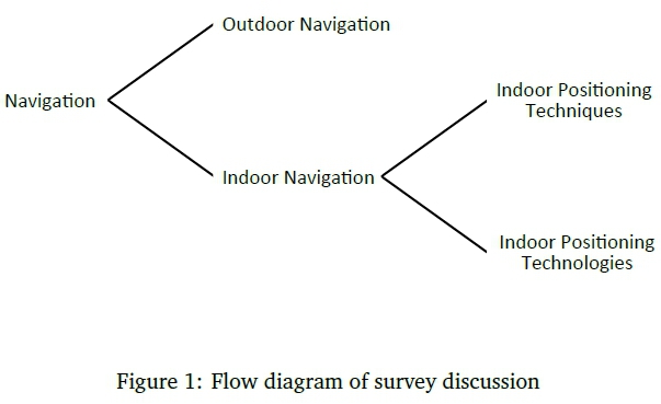
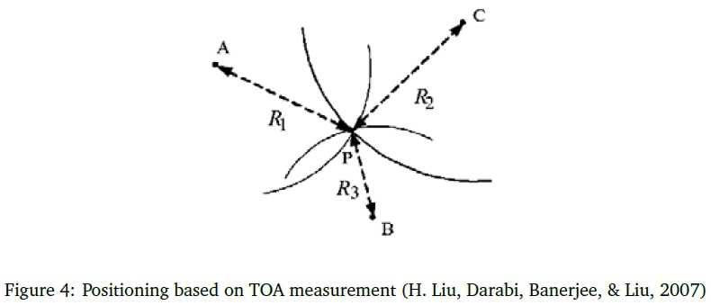
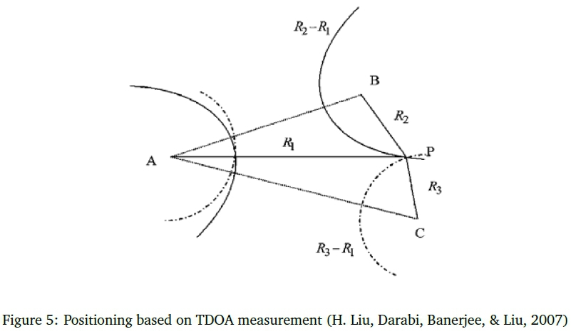
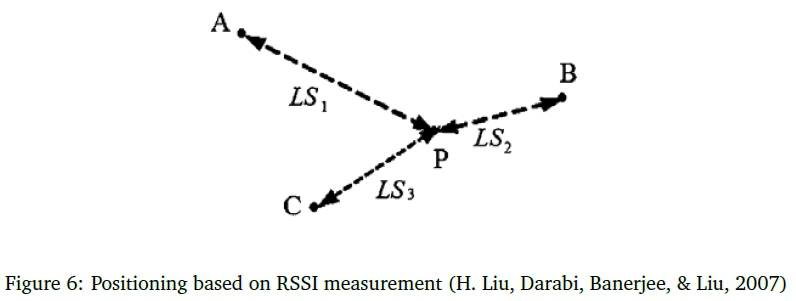
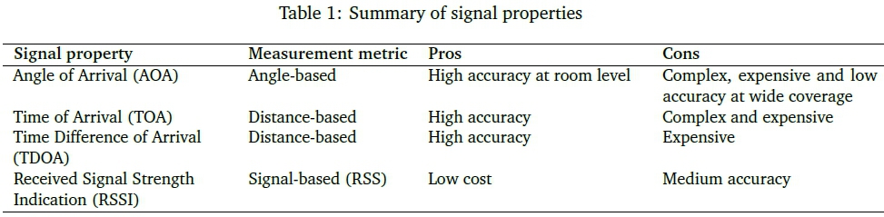
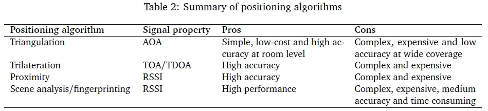
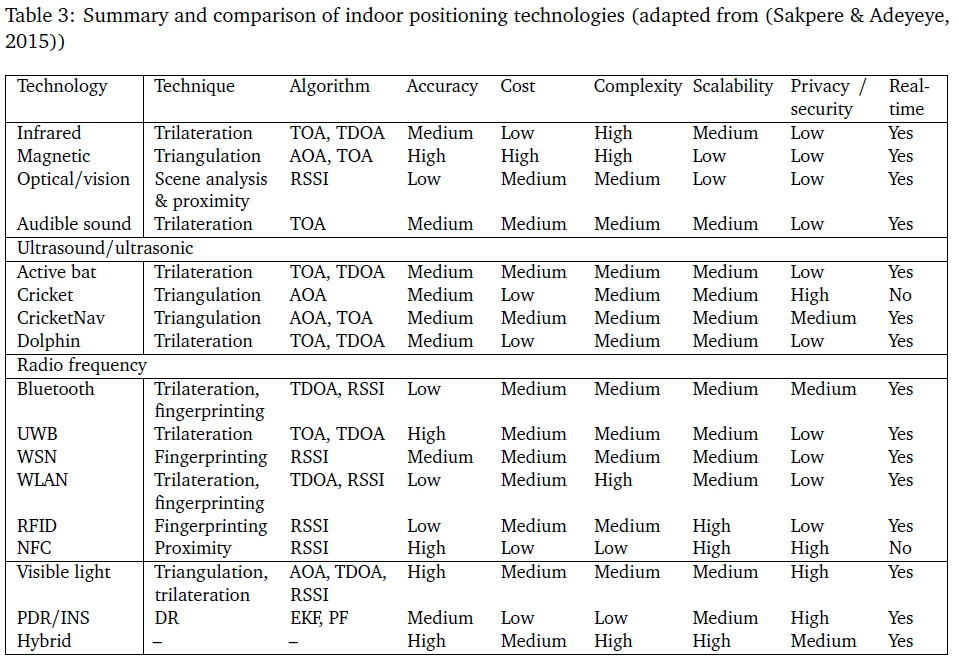