


Services on Demand
Article
 English (pdf)
 Article in xml format
 Article references
Indicators

Related links
-
 Cited by Google
 -
 Similars in Google
Share

 Permalink
South African Computer Journal
On-line version ISSN 2313-7835
Print version ISSN 1015-7999
SACJ vol.29 n.1 Grahamstown Jul. 2017
http://dx.doi.org/10.18489/sacj.v29i1.435
RESEARCH ARTICLE
A mobile augmented reality emulator for android
Donald MunroI; André P. CalitzII; Dieter VogtsIII
IDepartment of Computing Sciences, Nelson Mandela Metropolitan University, South Africa. donaldmunro@gmail.com
IIDepartment of Computing Sciences, Nelson Mandela Metropolitan University, South Africa. Calitz@nmmu.ac.za
IIIDepartment of Computing Sciences, Nelson Mandela Metropolitan University, South Africa. Dieter.Vogts@nmmu.ac.za
ABSTRACT
Augmented Reality (AR) provides a fusion of the real and virtual worlds by superimposing virtual objects on real world scenery. The implementation of AR on mobile devices is known as Mobile Augmented Reality (MAR). MAR is in its infancy and MAR development software is in the process of maturing. Dating back to the origin of Computer Science as an independent field, software development tools have been an integral part of the process of software creation. MAR, being a relatively new technology, is still lacking such related software development tools.
With the rapid progression of mobile devices, the development of MAR applications fusing advanced Computer Vision techniques with mobile device sensors have become increasingly feasible. However, testing and debugging of MAR applications present a new challenge in that they require the developer be at the location that is being augmented at some point during the development process.
In this research study, a MAR recorder application was developed as well as emulation class libraries for Android devices that allows the recording and off-site playback of video, location and motion sensor data. The research objective was to provide a software emulator which provides debugging, testing and prototyping capabilities for a MAR application including the ability to emulate the combination of computer vision with locational and motion sensors using previously recorded data. The emulator was evaluated using different mobile technologies. The results indicate that this research could assist developers of MAR applications to implement applications more rapidly, without being at the location.
Keywords: Mobile Augmented Reality, Emulation, Software tools
1 PREFACE
This paper is an extended version of a paper (Munro, Calitz, & Vogts, 2016) presented at SAICSIT '16 in Johannesburg, South Africa. The additions to the original paper are implementations of features that were described under the section on "Future Work". These changes comprise:
-
Using image stitching for interactive rotational recordings. The original concept was enhanced by the use of a 3-Up affine stitching of the current frame with the previous and next frame to provide an averaging filter which provides smoother frame transitions. The use of image stitching as a smoothing filter is a novel variation from the conventional use of stitching for image mosaicing.
-
As image stitching further extends the already onerous duration of the recording post-processing stage, a desktop post-processor was implemented in C++ which retrieves the intermediate recording files from the mobile device and carries out the post-processing on the desktop computer. Desktop computers with faster CPUs and more memory provide for much faster processing. In particular computers with graphics cards that boast a large number of GPU cores will benefit most.
-
Emulation support for the ARToolkit AR SDK is also provided.
2 INTRODUCTION
Recent computer hardware market trends have been shifting towards small, highly portable mobile devices such as smartphones and tablets. As a result of the demand for these devices, research and development have led to them becoming increasingly powerful and capable with multi-core Central Processing Units (CPU), Graphics Processing Units (GPU) and high definition displays. The Operating Systems (OS) used by mobile devices have also undergone a rapid evolution. Early mobile devices used proprietary embedded systems to control the hardware, however, contemporary devices have modern operating systems such as Android and iOS that are capable of supporting an ecosystem of user friendly applications.
Augmented Reality (AR) provides a fusion of the real and virtual worlds by superimposing virtual objects on real world scenery with the objective of enhancing the real world with computer generated objects or information in a composite 3D view. Craig (2013) provides a recent definition of AR which includes the attributes of interactivity and object recognition/registration as:
Augmented reality is a medium in which digital information is overlaid on the physical world that is in both spatial and temporal registration with the physical world and that is interactive in real time.
Spatial registration refers to the correspondence in location between the AR system or application and the physical reality which is being augmented whilst temporal registration refers to a correspondence in time between real world and virtual events. Real-time interactivity refers to the user of the AR system controlling how and from where the AR world is being viewed and what augmentation is displayed in real time as the user performs the interaction.
The increased power, portability and built-in sensors provided by modern mobile devices, combined with the improved ease of programmability provided by the Operating System (OS) has resulted in mobile devices becoming an ideal medium for AR applications with a new category of AR called Mobile AR (MAR) being born. MAR applications include AR browsers such as Wikitude (Perry, 2008) and games such as Google Ingress (Hodson, 2012).
As MAR is still in its infancy, software tools (Kernighan & Blauger, 1976) designed to enable and support MAR software development have been in short supply. The relatively recent introduction of Software Development Kits (SDKs) such as ARToolkit, Layar, Metaio, Vuforia and Wikitude has made MAR application development easier (Amin & Govilkar, 2015). However, while these SDKs do have some programming tools such as feature detection and database creation, they are still lacking in programming tools for debugging and prototyping applications. The objective of the software tools described in this paper is to provide a MAR debugging programming tool which can potentially also be used for prototyping.
Section 3 will describe the problem area in greater detail, followed by an overview of MAR emulation as a possible solution (Section 4). After discussing related work (Section 5), the design and implementation of software components implementing emulation as a solution are presented (Section 6) followed by an evaluation of the solution in terms of the design constraints laid out in the design section (Section 7). Limitations and future work is discussed in the final section.
3 PROBLEM DESCRIPTION
AR hardware can be classified by the visual presentation method and the position and type of the hardware used to display the AR scene (Van Krevelen & Boelman, 2010). Early AR research involved head-mounted transparent displays where virtual objects are projected onto the display over real world objects seen through the display (although transparent displays are still in use today as epitomised by Google Glass sunglasses). In contrast, modern Mobile AR (MAR) devices use hand-held video feeds utilising cameras combined with location and orientation information provided by device sensors (Wagner & Schmalstieg, 2003).
In terms of software techniques used for location, orientation and recognition, MAR applications can be classified by whether they are to be used in an indoor or outdoor setting (Azuma et al., 2001). Indoor MAR applications would typically combine fiducial markers1with rotational sensors. Outdoor and more advanced indoor AR applications would use Computer Vision2 (CV) feature recognition and tracking techniques or a hybrid of CV combined with Global Positioning System (GBS) location and orientation sensors.
The development of a CV based MAR application involves the developer in analysing and optionally augmenting video frames captured by a mobile device camera before they are displayed. These are possibly combined with orientation data used to help derive camera pose and locational GBS data to determine local Points of Interest (BOIs). A difficulty associated with outdoor MAR, particularly for software developers who typically tend to work indoors, is that testing and debugging a MAR application requires that they be at or near the location which is to be augmented. This follows from the spatial registration property in the definition of AR in Section 2.
Another frequent requirement for mobile AR development is the ability to debug applications or application prototypes on a desktop device. This requirement arises from:
1. The computing power provided by desktop computers still exceeds that of mobile devices by a wide margin.
2. It is faster and more convenient to debug on a desktop computer rather than having to do remote debugging on a mobile device using USB or WiFi connections.
Currently the most common solution is to create a video recording of the outdoor scene to serve as input to the desktop application. The video recording, however, does not preserve the orientation and location of sensor data so the desktop version cannot debug all facets of the mobile application.
4 EMULATION AS A SOLUTION
A possible solution to enable off-site debugging and testing of MAR applications would be to capture the video frames and the associated orientation and location data supplied by the device sensors whilst on site. Once this data has been stored, it should be possible to emulate being on site by playing back the stored video frames and sensor data. The playback could take two forms:
• Interactive: The recording is rotational only and the frames are indexed by directional bearings obtained from the orientation sensors. Later, when utilising the recording, the developer can interactively debug the application by rotating the device, thus using the current directional bearing to look up and display the appropriate recorded video frame.
• Non-interactive: The video frames, orientation data and location data are played back at a specified frame rate or at the same rate as when recorded.
In either case, the video frame can be passed to the debugged application in the same way as a live camera frame would be, thus allowing the application to analyse and augment the frame by using the same code it would for a live frame while simultaneously having access to the orientation and location data.
4.1 Emulator use in the MAR Development Model
The primary use for such a solution would be to enable debugging and testing during the implementation phase. MAR application development tends to be iterative and incremental. The development cycle involves implementing and testing CV, sensor and other techniques. The results from these tests are then used to fix errors, refine and improve existing functionality and add new functionality if the test results indicate the necessity. An indoor emulator is useful when using such an iterative model as it allows for repeated testing of several pre-recorded locations in order to compare test results and monitor improvements in the design.
Another use could be in the prototyping of proposed MAR applications. De Sá and Churchill (2012) propose a MAR prototyping approach based on low, medium and high fidelity prototypes. Low fidelity would simply be a hollowed out smartphone with a rectangular see through hole, medium fidelity would be videos edited to contain AR like icons and objects played back on a device and high fidelity would be a simplified prototype MAR application. In this context the proposed solution could be used in the creation of the high fidelity prototype for indoor prototyping. Having the AR emulation code closely match the real-world AR code would also make it easy for the prototype application to be used for a full outdoor prototype with minimal changes to the source.
5 RELATED WORK
Wither, Yun-Ta, and Azuma (2011) developed Indirect Augmented Reality, an AR solution which replaces the live video feed background with a previously captured panoramic image. However this technique was not designed as a software development tool for the emulation of AR, but instead as an alternative AR technique in which the user is still present at the location but the use of a panoramic video feed instead of a camera is used to provide an alternative tracking method which helps to reduce cognitive dissonance due to incorrect registration of real-world objects.
Berning et al. (2013) present an AR prototyping tool which uses a mobile device lens attachment to record a panoramic video which can then be edited by a video editor and played back by a player application on the mobile device.
Transform Flow (Williams, Green, & Billinghurst, 2013) is a MAR software tool designed to facilitate the evaluation of tracking algorithms. It consists of a recording component implemented on a mobile device and a playback viewer running on a Mac OSX or Linux desktop computer. The recorder records data from sensors to a Comma Separated Values (CSV) log file. Video frames are captured as Portable Network Graphics (BNG) image files and are also logged to a CSV file as paths to the aforementioned BNG files. The log files also include timestamps so that the sensor data and video frames can be temporally matched.
The playback application combines the recorded data with a developer-implemented motion model. The framework provides two sample motion models namely a sensor only model and a hybrid sensor/CV model.
There are limits to the solutions that software only emulations can provide. Ren, Goldschwendt, Chang, and Höllerer (2016) provide an example utilising a hardware AR emulation built at the University of California (Santa Barbara) which provides a more comprehensive emulation.
6 DESIGN AND IMPLEMENTATION
Analysing the requirements reveals the need for two separate software components:
1. A recording application which creates output files for camera frames, orientation and location data.
2. A class library providing an alternative implementation of the Android Camera and Camera2 API classes that can be plugged into the user's code to provide the AR emulation.
The overall design criteria for both components will be discussed in the following sub-section. This will be followed by a description of the high level design of the two components as illustrated in Figure 1.
6.1 Design Criteria
In order to provide a correct and comprehensive design the criteria that the design must meet will be defined in this subsection.
6.1.1 Real-time Constraints
The image and sensor streams occur in real-time and in the case of camera frames also constitute large volumes of data, all of which need to be handled in real-time. When this data is recorded, it also needs to be written to comparatively slow long-term storage.
During playback the different streams would need to be supplied to the client application asynchronously in terms of not allowing one stream to affect the playback rate of another stream. They must also be temporally synchronised so that events that happened at the same time during recording occur approximately at the same relative time during playback. For interactive playback, the playback device orientation sensors would also need to be monitored in order to be translated to the appropriate directional bearing. The debugged application using the playback classes may, in turn, carry out CBU intensive computation on the supplied frames.
These difficulties are accentuated by the fact that most of the processing (with the exception of where a desktop device is used for debugging) is to be accomplished on a mobile device with far less computing capability than a desktop computer.
6.1.2 Emulation Code Compatibility
In order to use the emulation the debugged application would inevitably need to be modified. The usability of the emulation would be diluted if the extent of the modifications are such that the MAR developer needs to maintain separate debugging and live versions or has to add large quantities of code, therefore any emulation would need to be as non-intrusive as possible.
6.1.3 Flexible Video Playback
When testing CV based applications, the ability to experiment with different video frame rates can be important as the application may encounter differing frame rates on devices of greater or lesser power or with different settings such as higher or lower video resolution.
The ability to have a higher maximum frame rate than would be encountered with a live camera, as well as the ability to set the maximum frame rate delivered to the tested application, would thus be an asset.
6.1.4 Orientation Sensor Sensitivity
The interactive solution variant introduces a dependency on the device s orientation sensors to determine the compass bearing of the device. This implies that the accuracy and stability of these sensors is of importance as errors could result in discontinuities in the recording.
There are several causes for potential orientation sensor inaccuracy or instability including:
• Gyroscope bias, which is the offset of the output from the true value when the device is not rotating, can adversely affect the output. Gyroscope bias increases linearly over time and thus accumulatively affects the integrated summation of readings. (See Vagner (2011) for a discussion and comparison of the accuracy of Microelectromechanical Systems (MEMS) gyroscopes which are used in mobile devices.)
• Accelerometers also suffer from bias, as well as from aliasing errors that occur when sampling the analogue signal to convert it to digital. Mobile device accelerometers are also low cost MEMS devices and thus suffer the same frailties as described above for MEMS gyroscopes.
• Magnetometers are easily affected by the presence of magnetic fields such as those commonly found in the vicinity of household appliances and computing equipment.
Having specified the criteria and constraints, the following two subsections will describe the design of the recorder and playback components including the steps taken to address the issues arising from these criteria/constraints.
6.2 Recorder Design
The recording process (see left hand side of Figure 1) stores orientation data, location data and camera frames to the devices long-term storage (usually an internal or external sd-card). Both camera frame and orientation sampling are CBU intensive processes requiring low-latency event processing as discussed in the design constraint on real-time performance in Section 6.1.1. Consequently, in order to maximise the quantity of stored data, a highly concurrent model is used which leverages the multi-core CBUs available in most modern Android devices.
A more detailed explanation of the mechanics of the recorder process, in terms of the components shown in Figure 1, is outlined in the following subsections.
6.2.1 Camera Frame Processing
The Frame Handler executes within the context of a camera preview callback which is executed by the Android Camera ABI every time a new frame is available. The handler calls a C++ Native Development Kit3 (NDK) (Android Developers, 2016) method which places the frame on a queue for processing by the frame-writer thread.
The frame-writer thread is a C++ class responsible for writing frames to storage. It comprises various Java Native Interface4 (JNI) methods for interfacing between Java and C++, an example being the method called by the frame handler to place a frame in the queue.
Once the enqueue method is called, the frame is copied because the Android ABI reuses buffer memory for subsequent frames, but is not copied again to ensure high throughput as memory copy can be expensive. A pointer to the frame is then placed on a single producer, single consumer lock-free queue. The writer thread dequeues the frame pointer and writes a timestamp, along with the frame contents, in the original YUV format5 (the exact variant of which depends on the Camera ABI used). Before writing, the frame can also be compressed by using the snappy compression library (Google, 2014b) which optimises for speed over compression. The timestamp is a nanosecond level timestamp relative to the start time of the recording.current time.
The camera-handler/writer performance could be further improved if the handler could also be written in C++ as there is some overhead calling C/C++ code using JNI. Unfortunately Android does not currently provide a documented NDK interface to the camera hardware6.
6.2.2 Orientation Data Processing
The orientation data is obtained via the Android Sensor Manager class from the hardware orientation sensors (usually some combination of gyroscope, accelerometer, gravity sensor and magnetometer). This data from the various sensors is blended together by using sensor fusion as implemented by Bacha (2013). The Rotation Vector synthetic sensor provided by Android, which also synthesizes data from various hardware sensors using a Kalman filter (Grewal & Andrews, 2015) is also supported and an adapter class is used to allow it to present the same interface as the sensor fusion classes. In both cases the sensor data is processed in a separate thread. The use of sensor fusion constitutes part of a strategy towards ameliorating the effects of orientation sensor errors as described in Section 6.1.4.
The orientation handler registers itself as a listener for orientation data from the sensor fusion component and the handlers callback method is invoked in the context of the sensor fusion thread. The callback method places the received orientation data on a ring buffer. It also signals the availability of new orientation data to other possibly blocked threads by using a conditional variable (Tanenbaum & Bos, 2015).
The orientation writer thread blocks on the abovementioned conditional variable and when it is signalled, removes all available data from the orientation ring buffer and writes it the orientation file. As with the frame writer, a relative timestamp is written for each record.
6.2.3 Location Data Processing
In contrast to camera frame and orientation data, location data does not require the same level of response to events because GBS hardware does not sample as frequently nor is it accurate enough for frequent sampling to be useful. The location handler again executes in the context of the calling Android Sensor Manager class is thus responsible for both processing and writing the timestamp and location data to storage as a separate writer thread is not necessary.
6.2.4 Recording Thread
The recording thread coordinates the recording process by synchronising when the handler threads start accepting events and the writer threads start writing data and it provides the recording start time, used as a base time, to subtract from the current time when writing timestamps. Once recording has started, it acts as a UI controller mediating with the handlers and writers in order to display progress and status updates.
6.2.5 Post-Processing
Once recording is completed a post-processing step creates the final recording file. This step is necessitated by the need to minimise per-frame processing time during recording so as to maximise the number of frames and the volume of orientation data that is stored. The CBU intensive work is thus postponed until the post-processing step.
The post-processing approach also allows for the heavy duty processing to be done on a desktop computer. In order to facilitate this, a C++ implementation of the post-processing code is available which also supports fetching the recording files from the device using the Android Debug Bridge (ADB) command line tool.
The first post-processing stage involves converting frames which were written to storage in the native YUV based format provided by the camera hardware to RGBA. This is done by utilising Android Renderscript (Google's equivalent of GBU acceleration libraries such as OpenCL or CUDA, which uses GBU cores for decoding if available). During this phase duplicate frames are detected using a Beak Signal to Noise Ratio (BSNR) algorithm (Salomon, 2006). When duplicates are detected, only the timestamps are retained. For interactive recordings negative (anti-clockwise) shifts between frames are also detected and removed. A smoothing filter is also applied to the orientation data. For non-interactive recordings the output from this stage is the final frames file.
For interactive recordings the next stage involves creating the frames file where images are indexed by bearing with the bearings ranging from 0 (magnetic north) through to 360 in a clockwise direction (that is bearings are implicitly stored as indices into the frame file). The bearing increments can range from 0.5 through to 3. This interactive frame file is created by reconciling video frames and bearings calculated from orientation data by using timestamps recorded with each record.
Upon finding a frame which best matches a given bearing, the frame can optionally be stitched together with the preceding and succeeding frame, providing an averaging filter which can provide smoother frame transitions. The stitching is implemented by finding matching features in the frames. An affine transformation matrix between the image features is then derived and this transformation is then used to warp the frame into a coordinate system common to the three frames being stitched. This should result in a smoother transition between frames, but adds appreciably to the processing time which makes the aforementioned offloading of post-processing to a desktop computer almost a necessity.
The final post-processing stage writes a header file containing all the recording parameters such as the path to the frames file and whether the recording is interactive. Details about the hardware camera used to make the recording such as the focal length and the field of view are also added to the header file if available.
Having described the design of the recorder component, the next section describes the design of the playback emulator classes which a MAR developer can use to play back recordings made with the recorder component.
6.3 Playback Emulation Design
Once a recording has been made, a means to playback the recording in a debug or prototype MAR application needs to be provided. This task is illustrated on the right hand side of Figure 1 and comprises supplemental emulation classes used in addition to the Android ABI camera classes by the MAR application. The emulation classes, in turn, use several different types of threaded playback components in order to asynchronously provide separate streams of emulation data.
When playing back an interactive recording, the playback device's orientation sensors will need to be used by the sensor fusion classes described in Section 6.2.2, to obtain the current compass bearing to use as an index into the frames file.
The use of these emulation tasks and sub-components is discussed below.
6.3.1 Emulation Classes
As previously discussed as a design constraint in Section 6.1.2, the use of a recording instead of input from a real camera should be as unobtrusive as possible. In order to accomplish this goal, the emulator provides mock implementations (Beck, 2002) of the Android Camera class and the new Camera2 API CameraDevice class. This allows similar camera setup and previewing code to be used for real and emulated cameras.
In addition to the Camera API methods, these classes also provide supplementary API methods specific to playing back recordings such as setting the recording header file. This allows the emulation user code base to minimize the number of changes required to switch from emulation to real code.
The emulation cameras can also use a real camera class as a delegate in order to have access to capabilities and setup parameters only accessible through the Android API. Construction and creation methods that include a delegate camera form part of the supplementary API methods mentioned in the previous paragraph.
Both mock classes also provide a separate, simplified non-emulating interface for developers who do not need nor want to emulate the Android classes, but instead would prefer to have separate code blocks for setting up real and emulated cameras.
6.3.2 Playback Threads
Several different thread variants exist depending on the recording parameters. It may have been possible to create a single monolithic thread handling all cases, but apart from being hard to understand and debug, such code would require many if statements to handle all the possibilities which, on modern CPU systems using pipelining and branch prediction, would lead to sub-optimal performance.
The main thread type differentiator is the playback type, that is, whether the recording is interactive or fixed. This is determined from the header file written by the recording thread (Section 6.2.4). Interactive threads can also be differentiated by whether to play continuously, that is, continue previewing the same frame determined by the compass bearing, or only call the preview callback once with the given frame. This corresponds to OpenGL render modes used when previewing a real camera feed. When using the continuous mode, a preset frame rate is used to regulate the rate at which frames are previewed.
The fixed (non-interactive) analogue to the continuous mode mentioned in the previous paragraph is whether to preview duplicate frames once only or as many times as they occur in the recording. The fixed playback thread classes can also preview at a selected frame rate, but, in addition can also play back at approximately the same rate as the original recording using the timestamps in the frame recording file.
The thread class selected controls the playback of camera frames which is the main driver in the process. This thread, in turn, starts subservient orientation and location playback threads. Both these threads preview data at a rate specified by the timestamps in their recording file. However, if a specified frame rate is used, then the frames would not be played back at their original rate which leads to the different streams being out of sync. In order to handle this case, the main thread places a timestamp for the current frame in a queue before previewing the frame. The subservient thread reads the timestamp from the queue and only previews data whose timestamp is less than the timestamp otherwise it blocks until the next timestamp is available.
6.3.3 OpenCV Integration
OpenCV4Android is an Android Java class library built on a JNI binding of OpenCV7 (Pulli, Baksheev, Kornyakov, & Eruhimov, 2012), providing an Android View which users can make use of in their user interfaces. The view provides camera preview and display facilities by using the Android Camera class. Although using these OpenCV views is not necessary to utilise the rest of the OpenCV library functionality, some OpenCV users may elect to use this view, so a view derived from the same abstract base class as the OpenCV view but utilising the emulation camera class instead of the Android one is provided. This enables emulator users who use OpenCV in Java for MAR development also to use the emulator without having to make a large change to their code base.
6.3.4 Desktop Support
Separate C++ classes also provide support for emulating recorded files on desktop computers using OpenCV. It should be simple to extend these to support other OpenCV bindings such as opencv-python for the Python language.
6.3.5 ARToolkit Support
ARToolkit ('Developing AR Applications with ARToolKit', 2004) is a popular multi-platform AR SDK that includes support for Android. ARToolkit defines an abstract video source defining an interface that the various hardware platforms override to interact with the rest of the SDK. An AARemu emulation video source was implemented which allows a developer to use either emulated or camera input when developing an AR application with ARToolkit. The underlying architecture of the emulation video source implementation is a simplified playback only version of the general AARemu emulation classes.
7 EVALUATION
In order to evaluate the effectiveness of the recorder emulator combination several possible metrics are discussed in this section.
7.1 Emulation Evaluation
In the following two subsections, the emulator is evaluated with respect to its design goals of providing configurable frame rates (Section 6.1.3) and providing drop-in compatibility between the emulating API and the real API (Section 6.1.2). The improvement in frame transition smoothness due to averaging by stitching of frames is also illustrated using a probability distribution histogram of frame shift data.
7.1.1 Frame Rate
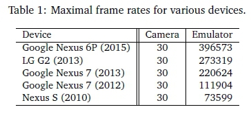
As a test of the number of frames per second that the emulator is able to deliver to client applications, a simple test application was created which only implemented a frame preview callback without any processing or rendering. A non-interactive recording was then previewed. The maximal frame rates achieved on modern devices far exceeded anything that would be delivered by a real camera (current Android devices achieve between 10-40 frames per second) or would be required by an AR application (or indeed would be displayable by the device screen hardware which is limited by the vertical refresh rate). See Table 1 for the maximal frame rates on several devices.
In addition to the maximum frame rate, the ability to set a specific frame rate using the emulation of the Android API was also tested (Table 2).

7.1.2 API Compatibility
In order to evaluate source code compatibility, two similar applications were implemented. One utilised the emulation and one used the Android hardware camera classes. These were simple applications providing a camera frame callback suitable for use in an MAR application. The emulation source file had 683 lines of code (LOC) while the hardware camera source file had 680 LOC. A text-difference command executed on the two files resulted in four differences comprising:
1. An extra line of code for the Java import statement for the emulation class.
2. A declaration of an instance-level camera emulation class in the emulation source or a Camera class in the hardware camera source.
3. An extra line of code to create a camera emulation instance class in the emulation code.
4. An extra line of code to set the recorded preview files to play back for the emulated code.
Regarding the above differences, all but the first two could be placed within an 'if' statement on a static boolean variable indicating whether to use emulation or a real camera. This would result in the Java Just in Time (JIT) compiler optimising out the unused branch. Based on this, it can be concluded that developers using the emulation should be able to switch between real and emulated code with relative ease.
7.2 Recorder Evaluation
The effectiveness of the recorder can be evaluated in terms of its efficacy in recording multiple streams of data from the camera and orientation/location sensors (Section 6.1.1) and its ability to minimize the effects of orientation sensor errors (Section 6.1.4).
7.2.1 Real-Time Performance
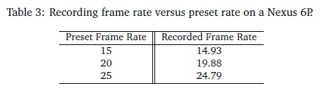
As part of the recording process, nanosecond timestamps are generated per frame. The data from several recording files were analysed to find the average nanosecond difference between frames for several recordings. This value was then used to derive the average frame rate which was compared with the preset frame rate used during recording. In each case the frame rate was within a few decimal places of the preset rate (see Table 3).
7.2.2 Sensor Error Handling
Sensor error affects interactive recordings more than it does non-interactive ones as in the latter case the errors are just forwarded to the application being debugged which should presumably be able to deal with them in real life. That being said, the recorder can smooth the orientation data by using an averaging filter as one of the post-recording processes executed by the recorder thread (Section 6.2.4).
For interactive recordings, the recorder records an image for a given bearing interval, for example, if the interval is set to one then an image will be recorded for the interval one to two, another for two to three and so on. During the recording process, if either the number of bearing readings in the interval or the number of frames written in the interval is too low then it may not be possible to match the given bearing interval to a frame.
Older or cheaper devices often have limitations on the camera preview frame rate, often limiting the frame rate to 15 fps. If a recording is made which takes 20 seconds with an increment of one degree then the number of degrees per second averages to 18, so if the frame rate is only 15 then it is inevitable that frames for some bearing increments will be lost.
Orientation data from which bearings are calculated also have hardware limitations according to the rate at which the orientation data is sampled. Factors influencing this rate include:
• Sensors, such as gyroscopes and accelerometers, sample their input at a fixed rate.
• Gyroscopes have a hardware-defined maximum angular velocity capability.
As a result of these limitation, accurate recording requires that the user rotates the device relatively slowly and smoothly during recording. Several heuristics were implemented to work around these issues as described in the next paragraph.
As part of the post-recording phases, the bearings and frames are filtered in several ways. Bearings are assumed to increase monotonically during the recording until the recording is completed when the current bearing equals the start bearing. The filter, therefore, rejects all bearing decrements (which could also result from the user recording jerkily). Similarly when frames are being matched to bearings, several comparisons between the current frame and the previous frame are made. The first comparison uses PSNR to eliminate duplicate frames. A Fourier shift test (Kuglin & Hines, 1975) which extracts the translation values between the two images is then applied and only positive translations, within acceptable bounds, are accepted as being a match. The matcher also automatically increases the bearing increment and restarts the matching process if too many matching errors are encountered. Additionally, a separate application was developed which allows a user to step through the frames and optionally correct an out-of-sync frame by taking a photograph to replace it.
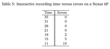
Table 4 lists the time taken for a recording, and the number of frame-matching errors for some sample recordings taken on a Nexus 7 which does have a 15fps limitation compared to a Nexus 6P (Table 5) which does not.

7.2.3 Frame Stitching
As described in Section 6.2.5, image stitching on three consecutive frames provides a form of averaging filter for interactive recording frames. The smoothing effect of this is illustrated in Figure 2 which provides a histogram with the frame shift differences on the horizontal axis and the number of shift occurrences on the vertical axis. As can be seen in the figure, the stitched recording has an improved distribution of frame shifts resulting in more consistent frame transitions.
8 CONCLUSIONS
An emulation such as the one provided by AARemu cannot fully simulate the developer's physical presence at an augmented location. Interactive recordings are rotational only; so the user cannot walk around the location, being restricted to horizontal rotational movements. Non-interactive recordings do allow free movement but do not allow interaction during the debugging process. Since the design goal was only to facilitate development of AR applications, it is hoped that this approach can at least allow users to debug CV feature detection in recorded frames and combine the CV output with location and rotation sensor output to emulate parts of an AR application.
The recorder/emulator combination does however provide a low cost and effective debugging and prototyping tool for AR developers who understand and can work around the limitations. For example, making multiple interactive and non-interactive recordings of a location can help overcome many of the limitations. By making the software extensible and publicly available it is also hoped that developers can enhance and extend the emulation to provide a customisable debugging tool for AR. The recorder/emulator therefore provides a research contribution towards the still maturing field of AR, and more particularly towards AR programming and debugging tools which have not received as much attention as other AR sub-fields.
9 FUTURE WORK
The advent of new AR supporting Android devices utilising the Google Tango (Google, 2014a) AR ABI may provide for the recording of 3D point clouds in addition to video frames and sensor data. This would provide emulation users with underlying 3D ground data.
10 AVAILABILITY
Both the recorder and the emulator are available from https://github.com/donaldmunro/AARemu (Apache open source license version 2.0).
References
Amin, D. & Govilkar, S. (2015). Comparative study of Augmented Reality SDKs. International Journal on Computational Sciences & Applications (IJCSA), 5. https://doi.org/10.5121/ijcsa.2015.5102 [ Links ]
Android Developers. (2016). Android NDK. Last accessed 15 Jun 2017. Retrieved from https://developer.android.com/ndk/index.html
Azuma, R., Baillot, Y., Behringer, R., Feiner, S., Julier, S., & MacIntyre, B. (2001, November). Recent advances in Augmented Reality. Computer Graphics and Applications, IEEE, 21 (6), pages 34-47. https://doi.org/10.1109/38.963459 [ Links ]
Beck, K. (2002). Test Driven Development: By example. Addison-Wesley.
Berning, M., Yonezawa, T., Riedel, T., Nakazawa, J., Beigl, M., & Tokuda, H. (2013). pARnorama: 360 Degree interactive video for Augmented Reality prototyping. In Proceedings of the 2013 ACM conference on Pervasive and Ubiquitous Computing Adjunct Publication (pp. 1471-1474). https://doi.org/10.1145/2494091.2499570
Craig, A. B. (2013). Understanding Augmented Reality: Concepts and applications. Burlington, MA: Elsevier. [ Links ]
De Sá, M. & Churchill, E. (2012). Mobile Augmented Reality: Exploring design and prototyping techniques. In Proceedings of the 14th International Conference on Human-computer Interaction with Mobile Devices and Services (pp. 221-230).
Developing AR Applications with ARToolKit. (2004), In Proceedings of the 3rd IEEE/ACM International Symposium on Mixed and Augmented Reality. ISMAR '04. IEEE Computer Society. https://doi.org/10.1109/ISMAR.2004.27
Google. (2014a). Project Tango. Last accessed 15 Jun 2017. Retrieved from https://get.google.com/tango/
Google. (2014b). Snappy: A fast compressor/decompressor. Last accessed 15 Jun 2017. Retrieved from http://google.github.io/snappy/
Grewal, M. S. & Andrews, A. P (2015). Kalman filtering: Theory and practice using Matlab (4th ed.). Wiley.
Hodson, H. (2012). Google's Ingress game is a gold mine for Augmented Reality. New Scientist, 216(2893), page 19. https://doi.org/10.1016/S0262-4079(12)63058-9 [ Links ]
Kernighan, B. W. & Plauger, P L. (1976). Software tools. Boston, MA, USA: Addison-Wesley Longman Publishing Co., Inc. [ Links ]
Kuglin, C. & Hines, D. (1975). The phase correlation image alignment method. Proceedings of IEEE International Conference on Cybernetics and Society, 163-165.
Munro, D., Calitz, A., & Vogts, D. (2016). AARemu: An outdoor mobile augmented reality emulator for Android. In SAICSIT '16: Proceedings of the Annual Conference of the South African Institute of Computer Scientists and Information Technologists. ACM.
Pacha, A. (2013). Sensor fusion for robust outdoor Augmented Reality tracking on mobile devices (Master's thesis, Augsburg University). [ Links ]
Perry, S. (2008). Wikitude: Android app with Augmented Reality. digital-lifestyles. info, 23(10). [ Links ]
Pulli, K., Baksheev, A., Kornyakov, K., & Eruhimov, V. (2012, June). Real-time computer vision with OpenCV. Commun. ACM, 55(6), pages 61-69. https://doi.org/10.1145/2184319.2184337 [ Links ]
Ren, D., Goldschwendt, T., Chang, Y., & Höllerer, T. (2016, March). Evaluating Wide-Field-of-View Augmented Reality with mixed reality simulation. In 2016 IEEE Virtual Reality (VR) (pp. 93-102).
Salomon, D. (2006). Data compression: The complete reference. Springer-Verlag New York, Inc.
Tanenbaum, A. & Bos, H. (2015). Modern operating systems (4th ed.). Pearson.
Vagner, M. (2011, April). MEMS gyroscope performance comparison using Allan Variance Method. In Proceedings of the 17th Conference STUDENT EEICT 2011 (pp. 199-203). NOVPRESS s.r.o.
Van Krevelen, D. & Poelman, R. (2010). A survey of Augmented Reality technologies, applications and limitations. International journal of Virtual Reality, 9(2), 1. [ Links ]
Wagner, D. & Schmalstieg, D. (2003, October). First steps towards handheld Augmented Reality. In Wearable Computers, 2003. Proceedings. Seventh IEEE International Symposium on (pp. 127135). https://doi.org/10.1109/iswc.2003.1241402
Williams, S., Green, R., & Billinghurst, M. (2013). Transform Flow: A mobile Augmented Reality visualisation and evaluation toolkit. University of Canterbury. Computer Science and Software Engineering. https://doi.org/10.1109/ivcnz.2013.6726992
Wither, J., Yun-Ta, T., & Azuma, R. (2011, August). Indirect Augmented Reality. Comput. Graph. 35(4), https://doi.org/10.1016/jxag.2011.04.010 [ Links ]
Received: 26 November 2016
Accepted: 1 March 2017
Available online: 9 July 2017
1 Fiducial markers are easily recognisable patterns which can be placed on real world objects to provide object recognition.
2 Computer Vision is a discipline whose aim is to develop techniques and algorithms which can be used for the analysis of images or sequences of images. The results from the analysis depends on the area of research and includes detecting and tracking 3D objects in the 2D image, determining the orientation and position of the camera in the 3D world (pose estimation), classifying detected objects by some class they belong to and 3D reconstruction of objects using multiple 2D images.
3 The NDK is an Android toolkit that facilitates the development of CBU specific native libraries using languages such as C and C++.
4 Java functionality that allows Java bytecode to call and be called by native CBU code such as C or C++. 5YUV format specifies how bytes representing colours in an image are laid out in memory - Y represents luminance while U and V represent two colour components that are combined with the luminance to represent a colour.
6 There may be a undocumented backdoor, via the now somewhat notorious Stagefright multimedia library.
7 An open source library providing comprehensive Computer Vision functionality.

