


Services on Demand
Article
 English (pdf)
 Article in xml format
 Article references
Indicators

Related links
-
 Cited by Google
 -
 Similars in Google
Share

 Permalink
R&D Journal
On-line version ISSN 2309-8988
Print version ISSN 0257-9669
R&D j. (Matieland, Online) vol.39 Stellenbosch, Cape Town 2023
http://dx.doi.org/10.17159/2309-8988/2023/v39a6
Fatigue Characterisation of Adhesives Used in Fibre-Reinforced Composites
I. MotlhakudiI; A. JonkerII
ISchool of Mechanical Engineering, North-West University, Potchefstroom, South Africa. E-mail: Isaac.Motlhakudi@nwu.ac.za
IISchool of Mechanical Engineering, North-West University, Potchefstroom, South Africa. E-mail: Attie.Jonker@nwu.ac.za
ABSTRACT
A review of past investigations into the fatigue behaviour of structural adhesives and bonded joints in fibre-reinforced polymer composites is given. An overview of the structural adhesives used in general bonded joint applications is first provided, followed by an experimental fatigue testing of these bonded components. The aspects that influence fatigue strength and fatigue life for adhesively bonded joints in fibre-reinforced polymer composites are then discussed in terms of the adhesive composition, geometry configuration, surface condition and preparation, and loading conditions. The aspects that relate to fatigue crack initiation and crack propagation in these bonded composite components are discussed in terms of damage modelling, monitoring, and detecting of crack initiation, crack growth rates and crack propagation modelling. The impact of environmental factors such as temperature and humidity on the fatigue performance of these bonded composite joints is also discussed. The paper then concludes by providing guidelines for characterising the fatigue behaviour of adhesively bonded joints and adhesives used in fibre-reinforced polymer composite applications.
Additional keywords: Stress-life; Constant-life; Damage Metric; Failure
Nomenclature
Roman
a Crack size [mm]
b Model parameter for damage model
C Material coefficient for Paris equation
D Damage variable
d Model parameter for reproducibility deviation
f Pressure-dependent yield criterion coefficient
G Strain energy release rate [J/m2]
J Yield stress [MPa]
J Amount of energy released per unit crack surface increase [kJ/m2]
k Number of test results per time interval
K Stress intensity factor [MPa m-1,2] l Failure stress [MPa]
m Experimentally determined constant
m Material coefficient for Paris equation
n Number of cycles per each load block
N Number of cycles
n Model parameter for crack propagation law
PModel parameter for crack propagation law
PNumber of different time intervals
RModel parameter for yield criterion
R Stress ratio
sStandard deviation
zModel parameter for damage model
Greek
ß Model parameter for yield criterion
Δ Range
ε Strain component
ϖ Model parameter for reproducibility deviation
σ Stress component [MPa]
ω Arithmetic average of test results for each time interval
Subscripts
1Failure stress or experimentally determined constant
2Yield stress or experimentally determined constant aAmplitude stress
cFracture toughness strain energy release rate
effEffective strain energy release rate
fFinal crack size or cycles to failure
iNumber of load blocks
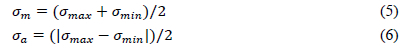
II Mode II
mMean
maxMaximum
minMinimum
oInitial crack size pPlastic strain
r Reproducibility standard deviation
rRepeatability standard deviation
TCombined modes strain energy release rate
thThreshold strain or strain energy release rate
yModel parameter for reproducibility deviation
1 Introduction
Engineering structures such as glider wings and wind turbine blades are currently manufactured from fibre-reinforced polymer composite materials, specifically from materials like glass fibre, carbon fibre, and aramid fibre in an epoxy matrix normally consisting of a resin and hardener. Different fibre-reinforced polymer composite parts are usually adhesively bonded to form the primary load-bearing structure; the structure's performance, therefore, depends on the performance of these adhesive bonds. The work done in [1] describes adhesively bonded parts as critical structural elements that must be able to transfer the developed complex stresses from one part of the structure to another. Thus, the importance of adhesively bonded joints in composite structures such as those in glider wings and wind turbine blades is evident. The use of adhesively bonded joints in composites was initiated in various military applications, where significant amounts of bonded polymer matrix composite laminates were used for parts such as wing skins and control surfaces [2]. The use of these components can also be found in many types of commercial aircraft, whose economic operations benefit considerably from reduced weight due to the bonded composite assemblies. Adhesive bonding can also be used in several repair and maintenance operations of gliders and wind turbines. The work in [1] explains that although each type of joint has its advantages and disadvantages, adhesively bonded joints are usually preferred for permanent connections. One key advantage of using adhesives in joining parts is that of higher fatigue resistance and longer fatigue life than other joining methods [3]. Light weight, ability to join thin and dissimilar components, good sealing, low manufacturing cost, and good vibration and damping are other advantages of using adhesive bonding. Adhesive bonding also serves as the most compatible joining method for composite structural parts due to co-curing and the brittle nature of the composite parts, according to [2].
The use of adhesive bonding in composites provides significant life-cycle maintenance cost and weight savings, as well as more uniform stress distribution, smooth external surfaces, and greater flexibility in design. However, one concern with adhesive bonding is its durability properties, especially fatigue performance [2]. Fatigue is an important type of loading for structural components that contain adhesive bonding systems [3]; a structure under fatigue loading may fail at a small percentage of static strength, which means that fatigue strength data is required for any new adhesive system to be characterised. Hence, this paper identifies and discusses some of the aspects involving fatigue and failure in structural adhesives. The selection process of an adhesive for a specific application is often complicated by the wide variety of available options; there is no universal adhesive that can fulfil every application [4]
In addition, new in-house adhesives with application-specific advantages over other adhesives are continuously being developed, examples include toughened epoxy (rubber toughened) and epoxy adhesives that consists of metallic or non-metallic filler particles. These therefore prompts investigations as to how these adhesives will behave under the expected environments and stresses for the fibre composite structural applications. In light of this, there is a clear need for a literature review that can shape and provide guidelines for how these investigations can be done. This paper hence reviews many articles in which multiple researchers investigated the fatigue behaviour of different types of adhesively bonded joints under different environmental and stress conditions. The aim of reviewing these articles is to develop guidelines that can be followed to characterise the fatigue behaviour of adhesive joints employed in fibre-reinforced polymer composite structural applications.
The paper consists of 7 sections for different topics. Section 2 of the paper discusses different types of structural adhesives in bonded joints. An in-house modified adhesive used in composite structures, consisting of epoxy with filler additives, is also discussed in this section. Experimental fatigue testing of joints in terms of test standards and precision of the test data is discussed in section 3. Section 4 then discusses the effects that the adhesive composition, joint geometry configuration, surface treatment, and loading conditions have on the fatigue strength and life of the bonded composite joints. Fatigue crack initiation and crack propagation are then discussed in section 5 in terms of damage modelling, crack initiation monitoring and detecting, crack growth rates and crack propagation modelling for bonded composite joints. The effects of both temperature and humidity on the fatigue behaviour of bonded composite joints as environmental factors are then discussed in section 6. Conclusions are then drawn in section 7 of this review paper.
2 Adhesives in Bonded Joints
Adhesives used in bonded joints are discussed in two parts for this section. The last part of the section provides some comments. The Advanced Manufacturing Technology Strategy (AMTS) standard workshop practice [5] suggests a criterion for selecting adhesives. The standard suggests that the following must be considered when choosing an adhesive:
• Maximum operating temperature: The maximum operating temperature of the component should not be more than that of the maximum allowable operating temperature of the adhesive.
• Elasticity: The properties of the adhesive after curing should match the properties of the components that are bonded together.
• Viscosity: A higher viscosity will create resistance against sagging during bonding and enables thicker bonds.
• Shrinkage during curing: An adhesive that tends to shrink when cured will cause deformation or total failure of the components when large areas are bonded.
• Cure temperature: The cure temperature should not be more than the maximum temperature that the component can resist as this can lead to failure.
• Bond line thickness control: Some adhesives contain micro-spheres to maintain the optimum bond thickness for the adhesive being used, to prevent the adhesive from being pushed out and bond thickness becoming too small.
• Compatibility: The adhesive should be compatible with both of the materials being used.
• Pot life: If the bonding procedure is complicated and needs a long time to complete, an adhesive with a long pot life should be selected.
• Cost: It is necessary to research alternatives to reduce the cost of the bond when joining materials
There is however a wide variety of structural adhesives available for different structural applications. Adhesive systems used in structural applications include epoxies, cyanoacrylates, anaerobes, acrylics, polyurethanes, silicones, and high-temperature adhesives such as phenolics, polyimides and bismaleimides [4]. Several typical properties of different types of adhesives are presented and discussed in Table 1 of the paper in [4]. An example of the use of cyanoacrylates is in [6]; the adhesive considered was a Multibond 330 (Loctite), which is a two-part (adhesive and activator) elastomer methacrylate used for general-purpose structural applications. An aluminium alloy supplied in the form of a cold drawn bar was used for adherends in a double cantilever geometry configuration. Fatigue tests were conducted on the bonded specimens to evaluate the influence of stress ratio (R-ratio) and loading frequency (f) on the fatigue crack growth. The crack growth rate (da/dN) vs Strain Energy Release Rate Range (ΔG) showed a typical sigmoidal shape. The paper then concluded that the strong influence of the R-ratio could be rationalised on most of the fatigue crack growth range, while the influence of the frequency was however much lower.
The paper on [7] discusses a fatigue life predictive model for electronically conductive adhesive joints under constant cycle loading using an electronically conductive adhesive. The adhesive used in the study was Loctite Ablestik MA 2, which is designed for bonding piezo crystals to stainless steel suspensions in the manufacturing of micro-actuated head gimbal assemblies [8]. Two single lap joint configurations with varying stress-states were designed using stainless steel 304 adherends. The tests were performed under monotonic and cyclic fatigue conditions, at 28 0C, 20% relative humidity, 50 0C, 90 0C and elevated humidity levels. Load versus number of cycles were generated using the two specimen's geometries at two load ratios (R-ratios) at a cyclic frequency of 150 Hz. A life-predictive methodology was developed and validated based on the experimental data.
The work done in [9] developed a mechanistically based model for predicting anomalous fatigue crack growth behaviour in adhesively bonded joints using lap-strap lap joints. The joints consisted of carbon fibre reinforced polymer adherends joined with an aerospace grade toughed epoxy film adhesive named EA9628. This adhesive is a rubber toughened single part epoxy film adhesive of 0.2 mm nominal thickness. The paper concluded anomalous fatigue crack growth in the bonded joints, which was attributed to the nature of the fatigue fracture. A complex fracture path was observed involving failure in both the adhesive layer and the composite fibre adherend.
The study in [10] investigated the fatigue crack growth rate of two high-temperature structural adhesives named EA-9649 and AF-163. Structural adhesive EA-9649 is an aluminium, asbestos and rubber-filled filmed adhesive which cures at 176 0C while AF-163 is a rubber-filled film adhesive with a nylon scrim cloth support and cures at 121 0C. The adhesives were cured with shims to control bond line thickness, 10mm and 20 mm bond lines were used. The adherend material used in the double cantilever beam joint configuration was aluminium alloy 2024-T351. The results revealed that there is a higher correlation between fatigue crack growth rate (FCGR) and the effective strain energy release rate range (ΔGeff)than between FCGR and the strain energy release rate range (ΔG). The 20 mm bond lines had higher fatigue crack growth rates than the 10 mm bond lines at equal strain energy release rate ranges for EA-9649 adhesive. Fatigue crack growth rates were equivalent for both bond lines when compared at an equal effective strain energy release rate range. The fatigue fractures always followed a cohesive fracture path.
2.1 Epoxy Adhesives
Epoxy adhesives are available for most bonding applications according to standard workshop practice [5]. These adhesives can be supplied as one part or as two parts called resin and harder. The two-part epoxies can be mixed according to the manufactures' data sheet in the correct ratios. Epoxy adhesives that are often used in composite matrices are commonly used to bond epoxy matrix-based composite components due to the compatibility between resin and the adhesive [4].
An example is the work done in [11], which used a two-part room-temperature curing epoxy adhesive consisting of parts known as Araldite 106 and Hardener HV 953 V. The adhesive was composed of a standard modified bisphenol A-based epoxy and was cured with the common polyamine amide hardener modified with a tertiary amine. The adhesive was used to bond adherends made out of commercial aluminium. This adhesive was used in a study to measure fatigue crack growth rates in a bond line of a double-cantilever beam specimen.
Another example is the study done in [12], where an adhesive used consisted of epoxy resin modified with a poly-amines hardener. The fatigue life of bonded scarf joints consisting of the adhesive and aluminium 5052-H32 alloy adherends was analysed experimentally at various scarf angles. The study in [13] employed a structural epoxy adhesive called EC-9323 B/A, produced by 3MTMScotch-WeldTM. The adhesive is a two-component epoxy paste adhesive which cures at room temperature or with mild heat to form a tough, impact-resistant structural bond [14]. The experiments from the study revealed that the fatigue strength increases significantly with the scarf angle of the joints. The main modes of failure for the joints with small and large scarf angles were adhesive and cohesive respectively.
The work in [15] used a two-component epoxy-based paste adhesive produced by a company called Weicon-Weicon GmbH & Co.KG in the experiments. The adhesive was used to bond aluminium 7075-T6 adherents in a single lap configuration joint. A new failure criterion was proposed to predict the static strength of these joints under tensile loading. The criterion is based on a simple 2D linear elastic finite element analysis and two material and geometry parameters. According to this new criterion, fracture occurs when the failure parameter along the adhesive mid-plane reaches a critical value at a critical distance.
2.2 Epoxy Adhesives with Fillers
The standard workshop practice on [5] indicates cost as one of the criteria for selecting an adhesive. The cost of bonds can be reduced by researching alternative adhesives according to the practice. The properties of adhesives may be altered by the addition of metallic or non-metallic filler particles, an example is the study done in [16], the effects of filler particles added to the two epoxy-based adhesives on the fatigue crack growth behaviour was investigated. The two commercially available adhesives were identified as A and B. The study also investigated the effect of the rubber present on the toughened adhesive B. The fatigue crack-growth tests in were conducted at 20 Hz and 2 Hz for adhesive A and at 20 Hz, 2 Hz, 0.2 Hz and 0.02 Hz for adhesive B. Double cantilevered beam joint specimens consisting of steel adherends were tested. Strain energy release rate (G) and crack driving force (J-integral) were evaluated. The tests showed that the fatigue crack growth rate (da/dN) for joints bonded with adhesive A was relatively independent of frequency while it increased with decreasing frequency at a given strain energy release rate range (ΔG) for joints bonded with adhesive B. The fatigue process for both adhesives involved the cracking of the filler particles and the subsequent linkage of the resultant microcracks.
Adhesives based on two-part epoxies are widely used by sailplane glider manufactures for the bonding of fibre composite structures [17]. These adhesives provide bonds for these structures that are strong and durable over a range of operating temperatures and relative humidity. Laminating epoxy such as the M.G. Scheufler resin system [18] for example, which consists of L285 resin and H287 hardener, may be used as an adhesive system on its own. However, this epoxy system has a low viscosity and cannot be used to form joints where strength is important [5]. Non-metallic fillers of types such as hollow spheres, short fibres or flow modifies may then be added in-house to improve these lacking properties [17]. These types of adhesives are highly cost-effective but require accurate mixing procedures to ensure consistency and strong bonds.
Modification of the M.G. Scheufler resin system by the addition of filler particles such as cotton flocks (short fibres), carb-o-sil (flow modifier) and glass micro balloons (hollow spheres) improves its viscosity and gap-filling properties [17]. The addition of cotton flocks specifically improves the adhesion, mechanical properties (shear strength), gap-filling properties and density of the mixture. The addition of carb-o-sil improves viscosity, mechanical properties (shear strength), and durability of the bond. Glass micro balloons increase the volume of the mixture and provide resistance to compressive forces while also providing low mechanical strength, which is good for bonding foam cores and non-structural surface filling. The addition of these filler particles to the M.G. Scheufler resin system can also ensure excellent bonds with numerous advantages over other tailored adhesives [17]. Some of these advantages include:
• High static strength
• Low shrinkage during curing
• Strong adhesion
• High thermal resistance
Static tests have confirmed the static bonding properties of this novel in-house adhesive system, but there is no data available for its fatigue properties. There is therefore a fundamental need to investigate the fatigue behaviour of these types of adhesives to develop a further understanding of the behaviour of fibre composite bonded joints, which form constituent parts of the glider wings.
2.3 Summary
The existence of a wide variety of structural adhesive options therefore gives rise to varies research opportunities to investigate the behavioural properties of these adhesives. In addition to the existing adhesives, the development of new structural adhesives also adds to these research opportunities. Different manufactures can adopt various in-house techniques to produce and modify adhesives that are needed for fibre composite structural bonding applications. Research into the behaviour of bonded joints composed of a typical adhesive under the action of various loads will therefore reveal the distinctive nature of that adhesive. Mechanical properties such as static and fatigue are some of the properties that can be investigated to study and characterise the behaviour of the particular adhesive and bonded parts consisting of that specific adhesive.
3 Experimental Fatigue Testing
Harris [19] describes the key requirement of any fatigue test machine as being able to perform different test modes (e.g., tension, compression, flexure, or shear) at a high number of cycles. The machine should also avoid excessive deflections and any resonant frequency of the machine or loading train should exceed the applied test frequency. The following factors, according to [19], affect fatigue testing and hence should be considered when developing a testing method:
• The rate of loading and the self-generated heat.
• The effect of buckling of specimens under compression loads.
• The effect of grip failures.
• Loading point stress concentrations and fretting.
• The effect of applied test temperature and stress concentrations.
Various standards therefore exist for coupon fatigue testing according to [19]. Standards such as ISO 13003 standard in [20] discuss the determination of fatigue properties under cyclic conditions. The general procedures for fatigue testing of fibre-reinforced composites under constant amplitude and constant frequency are described. These procedures apply to all modes of testing and test machine control. The first part of this section, therefore, discusses some of the testing standards that are available for adhesively bonded joints under fatigue loading. The second part of the section discusses the methods that can be used for determining the precision of the fatigue test data. Comments are made in the last part.
3.1 Testing Standards
Engineers have in the past developed many professional standards that can be used and followed to ensure the consistency and quality of scientific data [21]. The ASTM D3479/D3479M standard in [22] for instance stipulates two procedures that each define a different control parameter for the fatigue testing method of polymer matrix composite materials. The first procedure uses the strain in the loading direction as the test control parameter and the machine is controlled in such a way that the specimen is subjected to repetitive, constant amplitude strain cycles. The sample is thus loaded between minimum and maximum in-plane axial strain at a specified frequency. In this case, the number of strain cycles at which the sample fails can be determined for a specific strain ratio and maximum strain. The test control parameter can be described using the strain in the loading direction as a constant amplitude fatigue variable. The second procedure uses the load (stress) as a test control parameter where the machine is controlled in such a way that the test specimen is subjected to repetitive, constant amplitude cycles. The sample is loaded between minimum and maximum in-plane axial load at a specified frequency. The number of load cycles to failure can be determined for a specific load (stress) ratio and maximum stress. The test control parameter may be described using either the applied load or calculated stress as a constant amplitude fatigue variable.
The relatively large variety of joint designs for engineering applications and civil engineering structures is one of the factors that make standardization difficult for composite adhesively bonded joints according to [23]. There is also a wide variety of options for adhesives that exists as well. There are therefore no specific standard test methods for fatigue or fracture testing of adhesively bonded joints made from FRP composite materials such as the GFRP. However, one approach that can lead to standardization is by looking for existing test standards developed for other types of bonded joints, such as those developed for the characterization of fatigue, fracture, or fracture fatigue properties. Test standards that can be used for the characterization of fatigue, fracture or fracture fatigue properties include ASTM D3166 [24], ASTM D5868 [25], ASTM D-1002 [26] and ISO 9664 [27]. Testing standards such as ISO 14615 [28] can be used for durability testing of adhesives. An alternative approach will be to use the test standards developed for fatigue, interlaminar, static or fracture fatigue properties of fibre-reinforced polymer laminates, such as ASTM D3479/D3479M [22] and ISO 1524 [29].
3.2 Testing Data Precision
The type of data-gathering plan followed as well as the reliability of the instruments used to make measurements will affect the quality of data according to [21]. Hence the ISO 5725 standard in [30] describes the accuracy of measured results in terms of trueness and precision. The concepts of trueness and precision of a measuring instrument are statistical according to [21]. Trueness is defined as the closeness of agreement between the arithmetic mean of multiple test results and the true or accepted reference value. The ASTM E 691 standard in [31] also describes trueness as a general term used to express the closeness of test results to the "true" value or the accepted reference value. The trueness of measured data can therefore only be determined if a true or accepted reference value exists.
The precision of a measuring instrument describes the extent to which repeated measurements tend to agree with one another [21]. Precision according to ISO 5725 standard in [30] is defined as the closeness of agreement between test results obtained from the experimental investigation. The need to consider "precision" arises because tests performed on identical materials and identical circumstances will not yield identical results. This is because of the unavoidable random errors inherent in every measurement procedure, meaning that variability must be considered in practical interpretations of measurement data.
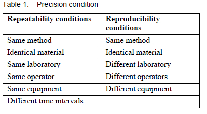
Harris [19] asserts that there is a requirement to provide the precision of measured or experimental data. Variability of experimental data may be due to differences in material batch, testing by different operators, or testing on different machines at separate times. There may also be uncertainties associated with a test method regarding the accuracy of load or dimensional measurements. Harris [19] goes further to explain that the precision of a test method is determined through experimental validation actions defined as repeatability and reproducibility. Conditions for both repeatability and reproducibility are shown in table 1.
Repeatability is therefore defined as the closeness of agreement between results obtained using the same method, the same material and under the same conditions (same operator, same equipment, same laboratory and at different intervals of time). Harris [19] also explains repeatability as the value below which the absolute difference between two single test results obtained under repeatability conditions is expected to lie within a probability of 95%. Repeatability may be expressed quantitatively in terms of the distribution characteristics of the results. According to Taylor et al, [32], the measure of repeatability is the standard deviation qualified with the term "repeatability" and is known as repeatability standard deviation.
The ASTM E691 uses the following equation to calculate repeatability standard deviation [31]:
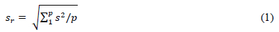
where p is the number of different time intervals, s is the standard deviation of test results from the arithmetic average value during each time interval, and sr is the repeatability standard deviation.
Taylor et al. [32] describe reproducibility as the closeness of agreement between the results obtained with the same method and identical test material, but under different conditions (different operators, different equipment and laboratories, and different time intervals). Reproducibility may also be expressed quantitatively in terms of the distribution characteristics of the results. The measure of reproducibility is the standard deviation qualified with the term "reproducibility" and is known as reproducibility standard deviation. The ASTM E691 uses the following equation to calculate the reproducibility standard deviation [31]:

where sr is the repeatability standard deviation calculated in Equation 1, k is the number of test results obtained per time interval, and sy is given by the following equation:
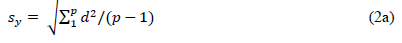
with d = ω - ϖ, where ω is the arithmetic average of test results for each time interval and

A repeatability exercise is therefore conducted within an experimental study and reproducibility is conducted by comparing with other experimental studies. The standard also explains that repeatability and reproducibility standard deviation provides an inverse measure of precision; high values of repeatability and reproducibility standard deviation imply low (or poor) precision of test results. Repeatability and reproducibility are therefore significant requirements for the precision of experimental data. The trueness of test results (as described above) can only be proved if true or accepted reference values of repeatability and reproducibility exist.
3.3 Summary
Using testing standards in the experiments ensures the consistency and quality of the experimental data. The most common test method for experimentally fatigue testing of composite adhesively bonded joints is to use stress or load as a control parameter under repetitive, constant amplitude loading. The test samples should be loaded between minimum and maximum in-plane axial load at a specified frequency for these fatigue tests. The two common methods to describe the precision of these experimental test methods and in so doing ensure consistency and quality of the test data will be to perform both repeatability and reproducibility analyses. Methods discussed in this section can thus be used to develop fatigue experiments where various effects on fatigue parameters such as fatigue strength and fatigue life of the bonded joint adhesive are investigated.
4 Fatigue Strength and Fatigue Life
Research studies that concentrated on the fatigue strength and fatigue life in adhesively bonded composite joints have been done in the past as indicated in [3], these studies indicated a further need of enhancing fatigue strength and prolonging the fatigue life of these bonded components. It is described in [33] that the intensity of stress causing failure (after a given number of loading cycles) is called the fatigue strength, which corresponds to that number of loading cycles. The fatigue life, which is measured as the number of loading cycles that a material can withstand before failing, can be described as being of utmost importance for fatigue loadings [34]. It has also been established through several tests that ferrous materials have an endurance limit, which is defined as the highest level of stress that can be withstood indefinitely without failure. The two approaches that can be used for the prediction of fatigue lifetime, according to [3], are the stress-life approach as well as the fatigue crack initiation and fatigue crack propagation approach.
Methods such as the stress-life approach are used in design and analysis to predict life in terms of the number of cycles for a specific level of loading [35]. The stress-life method is based on levels of stress only and is a traditional fatigue analysis method, since it is the easiest to implement for a wide range of design applications - a series of tests under various loads are typically performed to obtain the diagram of stress versus the number of cycles to failure (S-N diagram). The book in [23] concurs that one of the most explicit and straightforward ways to represent experimental fatigue data is through the S-N diagram. The approach is preferred for representing the fatigue life of fibre-reinforced polymer composite materials and structures since it requires input data that can be collected using very simple recording devices. Fatigue characteristics such as fatigue strength, fatigue life and endurance limit can then be established from the stress-life diagram. This section is divided into five parts to discuss the effect of different aspects on fatigue strength and fatigue life of bonded joints. The topics of particular interest are adhesive composition, geometry configuration, surface treatment as well as the effect of loading conditions. Some comments are then made at the end of the section.
4.1 Adhesive Composition
Historically, adhesives have been continuously developed and improved upon. An example is the study done in [2], where the mechanical performance of the newly developed epoxy LMB aerospace structural adhesive was studied. The adherends were laminates made out of carbon fibre-reinforced plastic. Double-cantilever beam and double-lap shear joint specimens were examined. The double-cantilever beam joint specimens were tested under static tensile and bending loads while the double-lap shear joint specimens were tested under static and fatigue shear loading. A comparison was performed between this newly developed adhesive and a qualified two-part paste epoxy adhesive named Epibond 1590 A/B. The comparison was done based on thermal ageing, wet ageing, fracture toughness and shear behaviour (static and fatigue) of bonded CFRP laminate joints.
The experimental results in [2] showed a higher fracture toughness and improved fatigue behaviour for the newly developed LMB epoxy adhesive over Epibond 1590 A/B. The static shear behaviour of Epibond 1590 A/B was however better than that of the LMB epoxy adhesive. This contradictory performance between the two adhesives was mainly attributed to the different chemical compositions and properties of these two adhesives. Thermal ageing at -50 0C/80 0C with a rate of ±5.5 0C/min for 1000 cycles degraded the performance of the joints. Wet ageing at a humidity of 85% under a temperature of 70 0C for 176 days enhanced the fracture toughness of the joints while degrading the shear response. Adhesive failure mode was observed in all the joints examined, which indicated poor bonded quality according to the authors.
The work done in [36] characterised mechanical behaviour and failure criteria for a developed adhesive known as SikaPower-4588 by using different testing systems, which is a thixotropic single-component adhesive with an epoxy and polyurethane base. Static testing systems consisted of tensile tests on bulk specimens, Arcan-Mines tests in different loading conditions, Thick Adherent Shear Tests (TAST) and single-lap tensile shear tests. Dog-bone-shaped bulk specimens were used for tensile tests while adhesive joint specimens were used for other tests. The mechanical behaviour and failure criteria were characterised to model the behaviour of the adhesive and failure criteria for both static and fatigue loading. The experiments showed the mechanical behaviour to be elastic-viscoplastic.
A pressure-dependent yield criterion was proposed as a failure criterion under static loading, using the following second-order polynomial equation:

where J2 and I1are yield and failure stress components in MPa. ßR20 and (ß-1)R0 are model parameters that were respectively identified as 190 and 7.4 via a series of tests for yield limit, and as 34676 and 39.5 for the failure limit of the bonded joints [36]. This static failure criterion was extended for fatigue loading by implementing the number of cycles as an additional parameter; this was done by taking ßR20 and (ß-1)R0 as -416log(N) + 4250 and -4.1log(N) + 54.27, respectively. A finite element simulation was also developed to validate the suggested failure criterion models.
The experiments in [36] also revealed that all the specimens tested failed in a cohesive mode, regardless of the test used. Arcan-Mines tests, TASTs and single-lap tensile shear tests were also performed for a lifetime study of the adhesive joints under fatigue loading, at a load ratio of 0.1. The fatigue tests also revealed that all the specimens tested failed in a cohesive mode, regardless of the applied stress level. The study also carried validation by finite element analysis simulation to confirm that the proposed viscoplastic pressure dependency model is suitable for this type of material.
Modern adhesives display a large amount of plastic behaviour, which in turn affects the fatigue performance of an adhesively bonded joint [3]. Reinforcing the adhesive material used in a joint to enhance fatigue performance has since been investigated by other researchers, various methods have been used recently to improve the mechanical properties of the adhesives, such as the modification of adhesive materials by incorporating various filler additives [37]. The study on [16] discussed in section 2 is an example, the work dealt with the effects of adhesive mechanical properties and microstructure on fatigue crack growth in steel-to-steel joints bonded with two commercial adhesives. The effects of fillers added to both adhesives on the fatigue crack growth were particularly investigated. The experimental results revealed that flat facets were observed in both adhesives examined, these flat facets are broken filler particles rich in magnesium silicate. Voids generally small in size compared to facets were also observed, these were presumably associated with debonded particles. The particles which debonded and resulted in voids contained no magnesium but had a high calcium content. The major fatigue crack growth mechanism was then proposed as the cracking of large filler particles and the subsequent linkage of these formed microcracks with the major crack.
The study in [37] evaluated the fatigue behaviour of the two-component epoxy named Araldite 2015 adhesive, reinforced with metallic fibre. Metallic fibres of Forta 304/4301 austenitic stainless steel, which consists of 18% chromium and 8% nickel, were used. The adherends were machined from a steel alloy. Single-lap joints were built and tested under various levels of fatigue loading to obtain stress-life curves. The fatigue tests were conducted at a room temperature of 200C, relative humidity of 26%, frequency of 30 Hz and a stress ratio of 0.1. The applied fatigue loads ranged from 40% to 65% of the static failure load. The experimental results showed that incorporating metallic fibres in an adhesive layer improves the load sharing in the bond line, which results in higher fatigue strengths for the bonded joint. The results also revealed that by decreasing the distance between the fibres, substantial enhancement can be obtained for the fatigue strength of the bonded joints. This was correlated to the lower peak stress values in the bond line. Another example is the work done in [38], where the adhesive investigated was epoxy LY219 with hardener HY5161, which was reinforced with unidirectional fibres, chopped glass fibres as well as micro-glass powder. Single-lap joints made of glass composite laminates and this adhesive were subjected to mechanical loads such as tensile, bending, impact and fatigue during experimental testing. The orientations of unidirectional fibres in the adhesive region were 00, 450 and 900, while the volume fraction of fibres in all cases was 30%.
The volume fractions of micro-glass powder were 20%, 30% and 40%. The results from the tests in [38] showed that the orientation of fibres has a significant effect on the strength and strain to failure values but no significant effect on the stiffness and therefore toughness of the joint. Maximum strengthening was achieved at 00 orientation while minimum strengthening was at 900 orientation to the loading direction. The results also showed that influenced both strength and stiffness but did not affect strain to failure of the joint.
The results in [38] further revealed that reinforcing the adhesive with micro-glass powder increases the strength except for the case of 900 unidirectional fibres. The 30% volume fraction of micro-powder showed the best performance in all loading conditions examined. The fatigue life increased by 125%, ultimate joint strength in tension increased by 72%, bending ultimate joint strength increased by 112% and the impact joint strength increased by 63% for this volume fraction. Three modes of failure could be observed, namely cohesive failure, light fibre-tear failure, and thin layer cohesive failure.
4.2 Geometry Configuration
The geometry configuration of adhesively bonded joints plays an important role in their fatigue strength and lifetime [3]. Joint geometry configuration is a product of design and, as a result, a wide variety of joints are available [4]. Single-lap joints, single-strap lap joints, double-lap joints, double-strap lap joints and stepped-lap joints are some of the commonly analysed configurations in the literature. Common joint designs as described by Hoke [39] are outlined in Table 2 below.
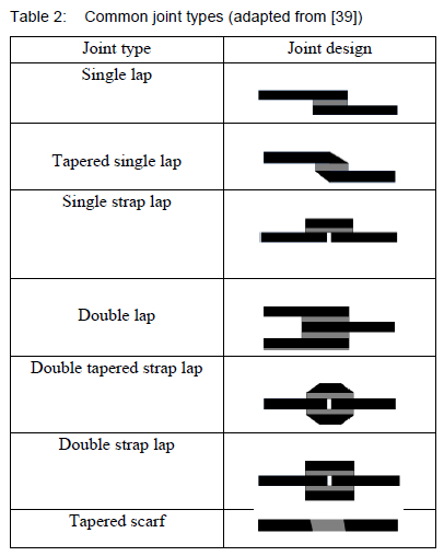
The black strip on the joint design indicates the adherend while the grey strip indicates the adhesive system. Many researchers have since investigated these and other different types of joint configurations and compared their fatigue performance [3]. The paper on [40] for example presents an experimental study on the full range behaviour of carbon fibre-reinforced polymer bonded to steel interfaces through a testing of a series of single lap bonded joints tested under static tension. Four different adhesives named Sika 30, Sika 330, Araldite 2015, and Araldite 420 were examined. One of the parameters evaluated in this study was the effect of the adhesive layer thickness for Sika 30 and Araldite 2015 on the bond strength. Three thicknesses, 1.5 mm, 2 mm, and 3 mm were used for Sika 30 adhesive. Two adhesive thicknesses, 2 mm and 3 mm were used for Araldite 2015 adhesive joints. Five single lap joint specimens were therefore tested to examine the effect of the adhesive thickness for these two adhesives. Loading was applied using a hydraulic jack, initially at load increments of about 1 kN, and then at properly adjusted displacement increments after the load-displacement curve became nonlinear.
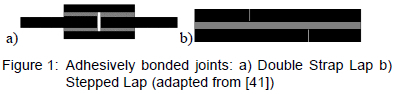
The results in [40] showed the bond strength increased when the adhesive layer thickness in the Sika 30 adhesive changed from 1 mm to 2 mm. The thickness of 3 mm led to a considerably lower bond strength than the 2 mm thickness. The authors concluded that the bond strength generally increases with an adhesive thickness. The low bond strength for the specimens with a 3 mm adhesive thickness could have been caused by some unexpected local defects in the bonded joint specimen. The two bonded joint specimens tested for Araldite 2015 adhesive with a thickness larger than 1 mm both failed by the interlaminar failure of the carbon fibre-reinforced polymer plate, both at a smaller bond strength. The work in [41] experimentally investigated stiffness degradation and fatigue life for double lap and stepped lap GFRP bonded joints shown in figure 1 under a single stress ratio representing tensile loading.
Constant amplitude fatigue tests were performed for both types of joints at a stress ratio of 0.1 and frequency of 10 Hz. Temperature and humidity levels were controlled to 230C and 50% respectively. Four different applied loads including 45 %, (48% for stepped lap joints), 55%, 65% and 80% of the ultimate static loads were used for each type of joint, these were selected to reach 102 and 107 cycles.
Critical stiffness was found for double lap joints tested in [41], while a critical elongation was found for stepped-lap joints at which failure occurs independently of the load level. Double lap joints exhibited almost linear stiffness degradation during fatigue, which remained low at around 5-7% of fatigue life. The rate was constant and independent of the applied cyclic load level. A linear model, therefore, represented stiffness degradation for these joints. Constant stiffness degradation was observed for single lap joints only between 20% and 80% of fatigue life for crack propagation. A sigmodal, therefore, represented stiffness degradation for these joints. It was also observed that stepped-lap joints have longer fatigue lives than double-lap joints for the same normalised load.
The study done in [42] investigated the effect of adhesive dimensions on the fatigue strength of epoxy-bonded single-lap aluminium joints. Single-lap specimens with different overlap lengths and adhesive thicknesses were used to examine the effect on fatigue strength. All the fatigue tests were load-controlled and performed at room temperature with a load ratio of 0.1 and frequency of 3 Hz. The work determined the local stress states at the interface between the adhesive and aluminium adherends using a finite element method analysis. Maximum interfacial peeling stress, maximum interfacial shear stress and a linear combination of interfacial peeling and shear stress were selected as parameters based on the simulated interfacial local stresses. These selected parameters based on the simulated interfacial stresses were considered to correlate with fatigue life data of all specimens with various adhesive dimensions.
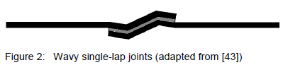
The experimental results in [42] revealed that under a fixed average shear stress condition, the fatigue strength of adhesively bonded joints increases as the adhesive thickness decreases. Fatigue strength also decreases as the overlap length increases, except for the specimens with an adhesive thickness of 0.5 mm. The results showed that the bending and peeling effects are important for determining the fatigue strength for the single lap joint specimen. The maximum average shear stress parameter failed to correlate with all fatigue life data of the specimens with various adhesive thicknesses and overlap lengths. Interfacial peeling stress and the linear combination of both interfacial peeling and shear stress provided better correlation than interfacial shear parameters, thereby indicating that the peeling stress is the main driving force of the fatigue failure of the single-lap joints. The failure mode of the studied specimens was adhesive dominant, indicating that the interfacial stress state strongly influences the fatigue strength. New or modified types of joints with higher fatigue thresholds and longer fatigue life have been proposed in the past by some researchers. An example is the work of [43], where a new design of a single-lap joint was proposed and experimentally investigated. A wavy-lap joint configuration, similar to the one shown in Figure 2, was suggested.
The material for the two adherends was a carbon/epoxy composite named AS4/350-6. Two different layup schedules, [90/0/90/0]2s and [0/90/0/90]2s were used for the two composite adherends. These adherends bonded together using a layer of film adhesive called FM73M, which is treated as an isotropic material. Load eccentricity and singular peel stresses were avoided in this new design of joint configuration. All joint specimens were tested under static loading at a crosshead loading rate of 0.001 mm/s. The onset of failure was monitored in situ using a microscope, and failed specimens were inspected using a high-power microscope.
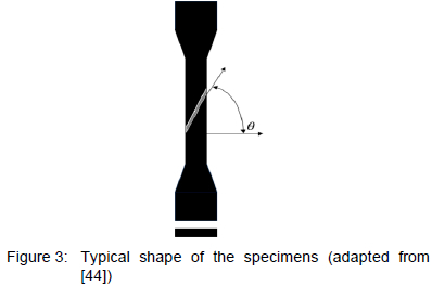
Numerical calculations showed that the peel stress becomes compressive in the joint end region and the shear load is more evenly transferred over the length of the joint. Experimental results in [43] revealed that the strength of the new joint is significantly higher than that of the conventional single-lap joint. This increase in the strength of the joint depends on the stacking sequence of the composite laminate adhered. The results also showed that the interfacial normal stresses in the wavy lap joint were compressive near the joint ends, in contrast to the conventional single lap joint which suffers singular tensile peel stress at both ends. The normal stresses were relatively small at the central portion of the wavy lap joint and could not initiate failure. Relatively large interfacial shear stresses were however present at the central portion, in contrast to the conventional single lap joint in which interfacial shear stresses vanish at the central portion. The work in [44], on the other hand, experimentally analysed the fatigue life of bonded scarf joints with various scarf angles, which are the angles between the bonding line and the plane normal to the specimen axis. Four types of specimens with adhesively bonded scarf angles (9) of 00,300, 450 and 600 were used in the experiments to study the effect of scarf angle on the joint specimens' tensile fatigue strength. The adhesive used was an epoxy resin with a modified polyamine hardener, while the adherend material used was aluminium alloy 5052-H32. Figure 3 shows the typical shape of the specimens studied in the investigation.
All fatigue tests were conducted at room temperature under load-controlled mode at a frequency of 3 Hz. The stress ratio used in all tests was 0.1 while maximum applied stresses ranged from 15-50% of the ultimate strength. The experimental results in [44] showed that the fatigue strength increases significantly with the scarf angle of the specimens. The failure mode for specimens transformed into cohesive from adhesive when the scarf angle increases. Interfacial peeling stress was the main driving force behind the adhesive failure, while the stress states within the adhesive contribute noticeably to the cohesive failure. The finite element method was also used to simulate the stress state within the studied scarf joint specimens. The simulated peeling stress along the interface decreased when the scarf angle of the joint specimen increased, which indicates that the failure mode in the bonded joint changed from adhesive to cohesive when the angle waw sufficiently large. The fatigue data of the joint specimens with 00/300 scarf angles and 450/600 scarf angles were successfully correlated using the maximum interfacial peeling stress at the bonding interface and the maximum von Mises stress on the middle plane of the adhesive.
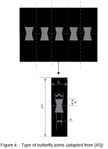
The work done in [45] experimentally examined the effects of butterfly Joints on failure loads and the fatigue performance of composite structures. A new design of butterfly joints was used in the study, as shown in figure 4 below. Butterfly-shaped joining components were used to connect the composite plates from their forehead by the tight-fitting method. Glass fibre composite materials were used to produce the composite plates. Fitting clearances were formed on the butterfly without making any changes in the dimensions of the specimens but by changing the dimensions of the butterfly. Butterfly joining components with the fitting clearance were set in their place on the specimen and then the clearances were filled with adhesive and then bonded. The adhesive used for bonding was Hysol 9464 epoxy adhesive. The specimens were then cut out from the composite plate, joined mechanically on the forehead, and the experiments were carried out.
Fatigue experiments in [45] were carried out on the specimens at the constant load ratio of 0.1 and frequency of 10 Hz. All fatigue tests were carried out at a room temperature of 230C and relative humidity of 50%. Different applied fatigue loads including 60%, 50%, 40% and 30% of the average static strength of the joints were used. Fatigue experiments of the butt joints were also carried out to compare fatigue performance. The experiments revealed that the fatigue strengths of adhesively bonded butterfly joints have a longer lifespan than those of the bonded butt joints under the same conditions. The work done made it possible that, with the use of the butterfly joining component, the earliest damage should occur on the butterfly and the joint should have a longer service life with the repair of the butterfly joining component.
4.3 Surface Treatment
The surface plays an important role in the bonding process, and it is also the most crucial zone governing the quality of an adhesively bonded joint [4]. The work in [46] concurs by stating that surface condition is an important factor. Surfaces should be prepared such that the type of failure that will occur in a joint is cohesive in the adhesive and not interfacial so that the full capacity of the adhesive is achieved. Bonding surfaces are therefore often abraded to remove weak or contaminated areas and to increase mechanical interlocking and the effective bonding area [47]. Failure of a joint occurring at the interface means that surface preparation needs to be improved [46]. Hence, surface preparation plays a crucial part in the quality of the interface between the adhesive and substrate and therefore influences the fatigue performance of a joint [3]. Failure in most adhesively bonded joints is due to poor processes during fabrication, with a lack of quality surface preparation being the most significant deficiency [48].
The work compiled in [4] states that the bond strength can be improved by surface treating the adherends before bonding. The work goes further to say that typical surface treatments for composite surfaces include traditional abrasion or solvent-cleaning techniques for thermoset composites, while thermoplastic composites require surface chemistry as well as surface topographical changes to ensure strong and durable bonds. The purpose of surface treatment for thermoplastic composites is to increase the surface energy of the adherend as much as possible. Surface treatments can increase surface tension, decrease water contact angle, and in doing so increase the bond strength of the joint. The paper further discusses various surface treatments that have been used in the past to increase surface tension, increase surface roughness, change surface chemistry and as a result increase bond strength and durability of adhesively bonded polymer composites joints. These include abrasion or solvent cleaning, grit blasting, peel-ply, tear-ply, acid etching, corona discharge treatment, plasma treatment and laser treatment.
The recommended surface preparation method for composites was however a light aluminium oxide grit blast in dry nitrogen [4]. The abrasion just removes the surface of the resin without exposing fibres with this method according to the authors. The paper in [49] further discusses various methods of surface treatment including traditional treatments such as acid etch, anodization, novel plasma spray and laser treatments for both fibre-reinforced polymer composites and titanium. These treatments were discussed for changes in surface tension, surface roughness, surface chemistry and how these changes affect the bond strength and durability of polymer composite titanium adhesive joints. Titanium surface treatments discussed included chromic acid anodization, sodium hydroxide anodization as well as laser treatment. Typical composite surface treatments discussed included traditional abrasion/solvent cleaning techniques for the thermoset composite. Thermoplastic composites according to the authors require surface chemistry and surface topographical changes to ensure strong and durable bond strengths. The authors then concluded that by increasing surface tension and roughness, as well as changing surface chemistry, a more intimate bond can be formed which allows for an increase in strength and durability.
The work done in [46] studied the influence of the macroscopic state of the aluminium alloy AA6082 substrate surface on the strength of adhesively bonded joints. Single-lap joints were built using a brittle adhesive named AV138 and a ductile Araldite 2015 adhesive to assess the influence of the type of adhesive. Several patterns were made on the surface of aluminium substrates. The patterns consisted of a series of grooves which were applied at 00,450 or 900 orientations relative to the sides of the specimen. The patterns were cleaned in two different ways, by using acetone and chemical cleaning with chromic acid etch. The patterns were consistently compared with the specimens without a pattern. The joints were tested under both static and fatigue loading. The specimens were tested under a crosshead displacement rate of 1 mm/min under a typical ambient condition of 25 0C and 50% relative humidity. All fatigue tests were done at a frequency of 10 Hz and a stress ratio of 0.1. Three levels of the applied load of 80%, 60% and 40% of the ultimate load from static testing were used.
The experimental results in [46] showed that the depth of the patterns that had high bond joint strength was 0.1 mm for both adhesives from tensile tests. The tensile tests of the bonded joints with AV138 showed that the surface patterns influence the joint strength, which was most notable in the specimens with no chemical surface treatment, where the patterned specimens had higher strength than the specimens with no pattern. This was due to the failure mode changing from adhesive to the mixed adhesive/cohesive mode. The patterns still influenced the joint strength with chromic acid etch-treated specimens, but the influence was considerably small since the failure mode was cohesive in all cases. Tensile tests with ductile Araldite 2015 adhesive revealed that the surface patterns do not have a significant influence on joint strength. This was due to the failure mode being already nearly cohesive in the case of no chemical treatment and no pattern.
Experimental results in [46] further revealed that fatigue testing with the brittle adhesive AV138 showed that surface patterns have a beneficial effect on the behaviour of the joint specimens under cyclic conditions. The patterned specimens consistently endured more cycles than the ones with no pattern, when no chemical treatment was applied at the same load. The surface patterns only had a substantial influence on the bonded joint strength when the failure is adhesive, which occurred with no chemical acid etching for this adhesive. The work concluded that the patterns could increase the joint strength of non-treated substrates in the case of brittle adhesive. Another example is the work done in [47], where the role of surface roughness on the fatigue behaviour of a toughened epoxy adhesive system was one of the characteristics investigated experimentally. The highly toughened single-part epoxy adhesive was used to bond aluminium double-cantilever beam and asymmetric double-cantilever beam specimens. The adherends, aluminium bars, were roughened in five different ways before bonding to produce five roughness measurements. These included abrading with an orbital sander using a silicon carbide nylon mesh abrasive pad, abrading with an orbital sander using P60-grit sandpaper and using grinder discs with grits P80, P36 and P16. The aluminium bar adherends were then washed with running tap water and a cotton cheesecloth and dried for 30 minutes at 55 0C. They were then pre-treated using the P2 etching process; degreased with acetone and etched using an aqueous solution of ferric sulphate and sulphuric acid. The bars were then rinsed using distilled water and dried at 55 0C for 30 minutes before the adhesive was applied.
Fatigue studies in [47] covered both the fatigue threshold strain energy release rate (Gth) and fatigue crack growth rates under Mode I and mixed-mode (Mode I + Mode II) fatigue loading. All fatigue tests were carried out at a frequency of 20 Hz under displacement control, with a displacement ratio of 0.1. A dry condition with a relative humidity of 11%-15% was achieved by doing the experiments in a desiccant chamber. The method identified as unloading joint compliance was used to measure the fatigue crack length. The experiments showed that surface roughness (Ra) had a significant effect on Gth under a mixed-mode fatigue loading where the crack path was very close to the surface. The smallest Gth was observed for the lowest tested roughness of Ra = 1.3 μm and increased by about 50% as Ra increased to 3.9 μm. This maximum value was also observed at Ra = 6.4 μm but decreased by about 20% for a very rough surface of Ra = 9 μm. The effect of surface roughness on the fatigue crack growth rate under mixed mode fatigue loading decreased as the crack growth rate increases. This was due to the crack path shifting farther from the interface as the strain energy release increased. The experimental results for Mode I fatigue loading showed no dependency on the surface roughness for both Gth and fatigue crack growth rates, due to the crack path being relatively far from the interface and well within the adhesive. The authors then concluded that surface roughness has a considerable effect only when the crack growth rate is low under mixed-mode loading.
One of the characteristics investigated in the study done in [50] was the effect of bond interface on the fatigue behaviour of a rubber-toughened adhesive. Mode-I loading was achieved using double cantilever beam specimens while two geometries of asymmetric double cantilever beam specimens, one with an adherend thickness ratio of 2 and the other with a ratio of 4 gave phase angles (Ψ) of 18 and 24 respectively. This angle is a measure of the mode ratio of loading. Cracked lap shear joint specimens were used to generate a loading phase angle of 500. The joint specimens consisted of either aluminium or steel adherends pretreated in several ways to achieve various interfacial bond strengths. The aluminium joints were fabricated using AA6061-T651 flat bars. The adherends in the majority of the fatigue joint specimens were abraded using a coarser aluminium oxide abrasive pad producing Ra of 1.33 μm with a standard deviation of 0.16 μm over 4 measurements. The bars were then pretreated using the P2 etching process. Degreased steel joints were manufactured from AISI 1018 steel bars, the adherends bonding surfaces were first abraded by using the aluminium oxide abrasive pad to produce Ra of 1.44±0.15 μm. The bars were then wiped using cheesecloth and acetone, degreased for 5 min in acetone, and finally rinsed with ethanol. The AISI 1018 steel adherends were given a standard Zn-phosphate pretreatment for some of the joints after abrasion with an aluminium oxide abrasive pad.
All fatigue tests in [50] were carried out under the same laboratory conditions and parameters as those discussed in [47]. The experimental results revealed that adherend surface roughness and surface preparation affected the fatigue behaviour significantly, particularly at low crack speeds and high phase angles. Surface roughness was found to improve the adhesive bonding under cyclic loading. An increase in surface roughness increased the residual adhesive thickness on the more highly strained arm and resulted in a fully cohesive failure for aluminium joint specimens. The fatigue properties were however the same for both steel and aluminium adherends provided the crack paths were cohesive.
The work on [51] investigated the effects of uniform surface pretreatment with a laser on the resistance of secondary bonded CFRP structures to model crack growth under mode I. The joint fatigue limit was characterised by carrying out displacement-controlled cyclic testing on the treated double cantilevered beam joint specimens. The study used infrared- range CO2 pulse laser with a 10.6 μm wavelength to treat the CFRP substrates to increase the fatigue limit and thereby expand the design envelope for secondary bonding. The cured substrates were then treated uniformly with either high (laser-ablated) or low (laser-cleaned) CO2 laser irradiation and compared with specimens that were treated with a baseline Teflon film to make bonding surfaces smooth. The adhesive used in the double cantilever joint specimens was a two-component epoxy named Araldite 420 A/B.
Static testing in [51] was carried out at a rate of 0.01 mm/s to initiate at 4mm crack in the joints. All fatigue tests were carried out at a displacement ratio of 0.1 with a frequency of 10 Hz. Crack propagation was monitored with a high-resolution camera which provided clear and highly magnified images of the crack tip. The experimental results showed the uniform laser treatment increased the fatigue limit evaluated at a threshold crack growth rate of 10-5 mm/cycle. The study done in [52], as another example, used a silane coupling agent called gamma-glycidoxypropyltrimethoxysilane (y-GPS) to promote the adhesive strength of the composite/metal joints manufactured with a co-cure bonding process. Co-cured bonded double lap joints between steel and carbon fibre-reinforced epoxy composite were studied. The thin layer of silane interphase between the epoxy resin of the composite and the steel surface was investigated. Steel adherends were made out of a material whose properties are similar to AISI 1045, after mechanical abrasion with P60 mesh paper, they were degreased with acetone in an ultrasonic bath for 2 min.
The surface treatment was then done using y-GPS as a silane coupling agent. Carbon/epoxy prepreg was used as outer substrates in the double lap joint specimens. Static tensile tests were performed on the joints at a crosshead speed of 1 mm/min and 20 mm/min. Load-controlled cyclic tensile fatigue tests were carried out at a stress ratio of 0.1 and frequency of 5 Hz. All fatigue tests were done at a normal temperature of 25 ± 3 0C and relative humidity of 50 ± 5%.
The tests in [52] showed that the silane interphase formation between the epoxy resin of the composite and the steel surface improved both the adhesion strength and fatigue life of the joints by chemical bonding introduced at the interface. The silane coupling agent coating of the steel surface produced a uniform film on the steel. The thin polysiloxane interphase between the steel and epoxy resin of the composite fills the gap at the co-cured epoxy/steel interface. Static testing results showed that the silane layer increased the joint's load-bearing capacity to about 1.5 times improvement. The failure mode in all static tests was partially cohesive. The experimental results of the fatigue tests revealed that the silane layer increases the fatigue life of the joint specimen. The fatigue crack propagation region of the joint specimen showed an interfacial failure mode.
4.4 Loading Conditions
The type, level and multiaxiality of loads have an important impact on the behaviour of adhesively bonded joints [3]. The work in [38] discussed above, investigated the adhesively bonded single lap joints subjected to mechanical loads such as tensile, bending, impact as well as fatigue. The study done in [53] investigated the fatigue performance of adhesively bonded 100 mm diameter composite pipe coupling joints subjected to external mechanical loading in terms of both axial and bending fatigue loads. The system considered was Ameron's 3420 glass-reinforced epoxy pipe, that incorporates a resin-rich reinforced liner and has a design pressure of 20 bar. Specific applications of this pipe system include potable water, fire protection, seawater, process piping and chemical waste. The adhesive used was called RP44, which consisted of both the resin and hardener. The main joint under investigation was the taper/taper adhesively bonded socket joint with a design wall thickness of 3.5 mm.
Fatigue tests in [53] were carried out in tension on quarter-sectioned joints, the authors' previous work indicated that quarter sections would give valid short-term results for failure mode and loads when co pared to complete pipe sections. The experiments were conducted at a frequency of 2 Hz and an R-ratio of 0.25. Some specimens were tested at an ambient temperature of 180C-230C, with a limited number of specimens being tested under 900C by heating with a surrounding furnace. Full-scale pipe sections were tested in a three-point bending over a 2 m span in flexural testing at a frequency of 0.167 Hz. Displacements ranging between 0-20 mm were applied to the specimens at a temperature of 900C. The experimental results showed that the ageing of the adhesive in an ambient environment can be beneficial to long-term fatigue performance. Axial fatigue loading was more significant in determining fatigue life than cyclic internal pressure. The elevated 900C temperature reduced fatigue life in both tension and bending.
The fatigue loads such as in axial loading may be repeated, variable or may fluctuate between different levels. The amplitude of fatigue loading may be constant or variable depending on whether the load applied is simple and repetitive (constant amplitude) or completely random and irregular (variable amplitude). Most laboratory fatigue tests, according to [19], are performed under conditions of both constant frequency and constant amplitude between minimum and maximum applied stresses. A constant ratio called stress ratio (load ratio), which is a ratio between minimum and maximum stress (load) is usually chosen and applied. The stress ratio can be determined for different peak stresses using the following equation:

where σmm and σmax are the minimum and maximum applied stress, respectively. The R-ratio is also used to identify the testing condition of fatigue loading applied. An R-ratio between 0 and 1 represents a pure tension fatigue loading condition, a ratio between 1 and +ꝏ represents pure compression fatigue, and a ratio between -ꝏ and 0 represents a mixture of tension and compression fatigue loading, which can either be tension-dominated or compression-dominated. The study done in [1], for instance, investigated the fatigue response of bonded pultruded Glass Fibre-Reinforced Polymer (GFRP) double-lap joints under different load ratios at R = 0.1, R = 10 and R = -1. Symmetric adhesively bonded joints composed of pultruded GFRP composite laminates bonded using an epoxy adhesive system were examined under axial tension, compressive and reversed fatigue loads. The laminates consisted of two mat layers on each side and a roving layer in the middle, with a thin layer of polyester veil on the outer surfaces of the laminate. A two-component epoxy adhesive system called Sikadur 330 was used for bonding.
All experiments in [1] were performed under laboratory conditions of temperature of 23±50C and the relative humidity of 50±10%. Static tensile and compressive experiments were carried out under two different modes. The modes were displacement control mode (designated as low loading rate) with a ramp rate of 1 mm/min and load-control mode (designated as high loading rate) with a ramp rate of around 350 kN/s. All fatigue tests were done under load control using a constant amplitude sinusoidal waveform at a frequency of 10 Hz.
The experimental data in [1] covered an entire lifetime between one and five million cycles. Seven load levels for R=0.1 and five load levels for R=-1 and R=10 were selected for the tests. The experiments revealed that the fatigue life of the joints was shorter for pure tensile loads and longer when pure compressive loads were applied. The dominant failure mode was a fibre-tear failure that occurred in the mat layers of the laminate for the tensile and reversed loadings, while the failure was driven by a crack in the roving layer in the case of R = 10. A decrease in joint stiffness of about 8% was observed for the tensile and reversed loading conditions, while a very limited stiffness degradation of around 2% was recorded under compression. The results proved that there is no correlation between the applied load level and stiffness degradation at failure. Similar crack development was observed independent of the failure mode. This was characterised by an initial and final region of accelerated propagation, and a middle part of linear and slower crack propagation, corresponding to around 80% of the fatigue life. The work done in [54] investigated the effect of the mean load on the fatigue behaviour of GFRP double-lap joints, by experimentally testing at nine different stress ratios that represented pure tension, pure compression and a combination of both tension and compression fatigue loading. As in [1], symmetric adhesively bonded joints composed of pultruded laminates and bonded using an epoxy adhesive system were once again examined under axial tension, compressive and reversed fatigue loads. The laminates consisted again of two mat layers on each side and a roving layer in the middle, with a thin layer of polyester veil on the outer surfaces. A two-component epoxy adhesive system named Sikadur 330 was again used as an adhesive system. All fatigue experiments were performed under laboratory conditions similar to conditions in [1], under load control and using a constant amplitude sinusoidal waveform at a constant frequency of 10 Hz. Six more R-ratios in addition to the ones tested in [1] were examined for this work, these included R=0.5 and R=0.9 for pure tension fatigue, R=2 and R=-1.1 for pure compression fatigue as well as R=-0.5 and R=-2 for mixture of tension and compression fatigue loading.
The experimental results in [54] showed the high dependency of the fatigue strength on the mean load. The increase of the mean load under constant amplitude led to an increase in the tensile and compressive fatigue life. The experiments showed the slope of the stress-life (S-N) curves (derived for R-ratios with positive or negative mean load) to be consistently decreasing with an increasing mean load. The experiments showed that a transition of the failure mode, from tensile to compressive, was observed as the mean load decreased from positive to negative values. The highest load amplitude corresponded to the R-ratio where the transition of the fatigue failure mode occurred, namely at R = 2.
Fatigue loads can be decomposed into mean and amplitude loads. The combined effect of these loads on fatigue life is normally investigated through the use of constant life methods [54]. The constant life diagram (CLD) is typically used to examine this effect. The conventional method of plotting the CLD is done by using the relationship between mean and amplitude components at any constant life according to [55]. Fatigue data at any stress ratio is plotted on the mean-amplitude plane as radial lines starting from the origin of the coordinate system [54]. The CLD is then formed by joining, in a linear or nonlinear way, the points corresponding to the same number of cycles on consecutive radial lines. The CLD also represents various stress-life curves (S-N curves) for different R-ratios on the mean-amplitude stress plane. The main parameters of CLD are mean stress (σm), amplitude stress (σa), number of cycles (N)and the stress ratio (R-ratio). Mean and amplitude stress can be determined from minimum and maximum stress values by using the following equations, respectively [35]:
The relationship between mean stress, amplitude stress and R-ratio for any number of cycles can thus be determined from the above equations:

Hence, the combined effect of both amplitude and mean stress on the fatigue life can be illustrated in the σm and σaplane as lines radiating from the origin of the coordinate system. The constant life derived for the experiments in [54] was asymmetric and shifted toward the compressive domain. This was found to be consistent with higher fatigue strength of joints under compressive loading. An exploration of full shape, as well as the development of an efficient CLD for the prediction of the fatigue life for multidirectional carbon fibre-reinforced plastic (CFRP) laminates, is discussed in [56]. Three kinds of CFRP laminate layups were tested at room temperature under pure tension (T-T), pure compression (C-C) as well as under the mixture of tension and compression fatigue loading. The [45/90/-45/0]2s, [0/60/-60]2s and [0/90]3s layup schedules for the laminates were examine. Two stress ratios were examined under each fatigue loading condition. The experimental results showed that the CLD of the laminates becomes asymmetric about the amplitude stress axis for the fatigue loading in the fibre direction. The shape of the CLD curves progressively changed from a linear to a nonlinear curve as the value of fatigue life changed. This nonlinear shape of the CLD in the longer fatigue life could be described approximately using a parabola. Similar features were observed for all CFRP laminates tested in the study; this fact serves to explain that the three types of laminates have similar mean stress sensitivity to fatigue.
The constant life diagram can also be used as a model to predict the fatigue life of the material under loading patterns for which no experimental data exist [23]. However, more sophisticated formulations with more parameters may be necessary to improve the accuracy of these predictions. An example is the work done in [54], where a new phenomenological formulation of the constant life diagram was proposed for the simulation of the fatigue life of the joints by also considering creep-fatigue interaction. The accuracy was evaluated by comparisons with the derived experimental data. The comparison of this new formulation with models commonly used for composite materials proved that its higher accuracy is achieved with less implementation effort.
The paper in [55] discusses a new method called a nonlinear multi-slope model for combining the measurements with a new type of three-dimensional model and compares it with the traditional model in terms of accuracy. The model is derived by using the Gerber model, normally used for ductile materials, as a starting point. The author concluded that the multi-slope model had a good fit with the measured data points. The standard deviation of all points was more than half the standard deviation in the traditional model. A drawback of the model was that it loses accuracy for a very low number of cycles, and it ignores static strength. The work done in [56] also developed a nonlinear constant life diagram formulation for the prediction of fatigue life for multidirectional CFRP laminates. The CLD is based on the static strengths in tension and compression and also references the S-N relationship fitted to the fatigue data for the critical stress ratio. The CLD predicted using this new formulation corresponded well with the experimental CLD regardless of the type of the CFRP laminate. The S-N relationships predicted using this new method also corresponded well with the experimental results for all the stress ratios in the range of the fatigue life up to 1 × 10⁶ cycles, also regardless of the type of laminate.
The work done in [57], on the other hand, examined the influence of the CLD formulation on fatigue life prediction of composite materials. Commonly applied CLD formulations (as well as recently proposed CLD formulations used on composite materials fatigue data) and their applicability were demonstrated on several data sets. Fatigue data was taken from several well-documented databases. The influence of the chosen CLD formulation on the fatigue life prediction of material under spectrum loading was assessed by its ability to accurately predict unknown S-N curves for random loadings. The results showed that the S-N predictions based on the simple piecewise linear formulation were the most accurate compared to other formulations.
4.5 Summary
The development of new adhesives and bonding techniques with different geometries and surface treatment methods can therefore further the enhancement of fatigue strength and increase the fatigue life of adhesively bonded joint parts as shown by studies above. There is always therefore a research opportunity for more knowledge in terms of the fatigue behaviour of bonded parts due to these developments and innovations. An inhouse modified adhesive such as the one discussed in section 2.2 for example, can be investigated to further understand the effect that various combinations of epoxy and additives have on fatigue strength and fatigue life of the bonded joints. The effects that different joint geometries, adherends surface treatment methods, as well as the fatigue loading conditions have on fatigue strength and fatigue life of this adhesive can also be investigated. This can enhance understanding of the fatigue behaviour of adhesively bonded joint parts made from the adhesive. The percentage of the total fatigue life spent in both initiation and propagation of fatigue failure is not however covered in this method.
5 Crack Initiation and Crack Propagation
Several methods have been used in the past to characterize the fatigue behaviour of engineering materials and structures, these included the development of procedures to accurately model and predict fatigue life [58]. These methods can be based on the phenomenological representation of the material or structural behaviour, expressed using S-N curves and associated CLDs discussed above in section 3. The stress-life method only records the number of cycles to complete failure to characterise fatigue according to [59]. Other methods can be based on the damage metric representation of the structure's durability, which can be monitored in fatigue loading and can indicate how close is the material to failure [58]. Examples of damage metrics include stiffness, crack density and crack length.
Using crack initiated and propagated in the material during fatigue loads as the damage metric has proven valuable for metals according to [58]. A specimen subjected to cyclic loading can have a fatigue crack initiated on a microscopically small scale, followed by crack growth to a macroscopic size, and finally specimen failure in the last cycle of the fatigue life [60]. However, this concept still needs further research for composite materials, in which failure occurs as a result of the interaction of different phenomena such as matrix cracking, delamination or fibre cracking. The failure in adhesively bonded composite joints is nevertheless the result of a dominant crack that can be used as an acceptable damage metric when monitored during fatigue loading.
Fatigue lifetime using damage metric can therefore be divided into two main phases, which are crack initiation and crack propagation [3]. The crack initiation and crack propagation are considered separate because several practical conditions have a large influence on the crack initiation period yet limited or no influence on the crack propagation period [60]. The first two parts of this section, therefore, focus on damage modelling as well as crack initiation monitoring and detection in adhesively bonded joints. The last two parts then focus on fatigue crack growth rates and crack propagation modelling. Comments are then provided in the last part of the section.
5.1 Damage Modelling
The most important difference between glass fibre composites and metals is the fatigue damage process [61]. Fatigue loading results in creating areas of repeated plastic deformation in metals. Fatigue damage in materials such as glass fibre composite is mostly continual and global in volume. Models to simulate damage can either be scientifically based on continuum damage mechanics theory or empirically be based on a plastic strain or principal strain [3]. Palmgren-Miner rule is an example of continuum damage mechanic theory that can be used to model damage accumulated in materials subjected to fatigue loading [62]. The damage based on this model is calculated independently of the loading sequence and pattern under variable amplitude fatigue loading. The model is shown below for k blocks in the work done by [62]:

D is the damage index, and niand Niare respectively the applied number of cycles in each loading block and the allowable number of cycles under the applied load level. The specimen under the loading, therefore, fails when the damage index is one. A simple modification to this rule was then in the work done [62]. The work then concluded that several conceptual approaches can be used to describe damage accumulation in composite materials.
The work done in [63] for example, developed a progressive damage fatigue simulator called fatigue damage simulator (FADAS) for variable amplitude loads. The simulator executes ply-by-ply stress analysis in composites using classical lamination theory and models the degradation caused by a failure in the ply level.
Many authors have since used models that are empirically based on plastic strain to represent damage accumulation in the materials. In most of these models, the damage accumulated is related to plastic strain through a power law function. One way of representing damage in adhesively bonded joints according to the paper in [64] is to degrade the constitutive properties of the adhesive, which is represented in the paper as an elastoplastic response. The study in this paper developed an elastoplastic damage model that could predict the experimentally observed back face strain patterns and fatigue life at different fatigue loads. The model is based on maximum fatigue strain, which thereby drives fatigue damage. First, the experimental data was obtained by testing single-lap joints at constant amplitude and constant frequency of 5 Hz. Fatigue testing was done at 50%, 40% and 30% of the static shear strength of the joints. The joints consisted of aluminium substrates and FM-73M as an adhesive. Six self-temperature strain gauges with a gauge length of 1.5 mm were placed along the overlap of the single lap joint. The back face strain profiles obtained from the gauges depend on the load applied, and strain values against the number of cycles curves were plotted.
The results of the experiments in [64] were analysed together with the fatigue results of the study done previously by the authors. At higher loads, the life was shorter, and the back face strain trend was an initial region of moderate change, followed by the transition until reaching a peak. The joint tended to fail as gauges 1 and 4 approached peak values. The joints could sustain more extensive damage before final failure, this could be demonstrated by the more extensive back face strain profiles developed at the lower loads with the transition region occurring at the relatively earlier part of the fatigue life. The damage model based on the following power law function was then developed:

where D is the damage variable. The damage rate is calculated at each adhesive material integration point, where ΔD/ΔN is the cyclic damage rate, εmax and εth are the respective adhesive maximum principal strain and threshold strain at that material integration point. The parameters b and z are used to calibrate the damage model. The damage at every adhesive material integration point is updated in every increment using the following equation, up to a limiting value of D = 1 (fully damaged):

where i is a time-step index and N is the number of cycles. The model was implemented in a finite element analysis code and used as a user-defined subroutine to calculate the damage, as well as the resultant degradation in the adhesive Young's modulus and yield stress. It was observed that as the damage progressed, the elastic modulus reduced from 2000 MPa (undamaged) to 2 MPa (fully damaged), while the yield stress reduced from 64 MPa to 6 MPa.
In the work of [65], a unified model able to predict the fatigue behaviour of adhesively bonded joints was proposed. The model is based on a damage mechanics approach where the evolution of fatigue damage in the adhesive is defined as a power law function of the micro-plastic strain:

where D is the damage variable, which is equal to 0 for undamaged material and 1 for complete damage. N is the number of the fatigue cycles and hence dD/dN is the damage rate. The parameters m1 and m2 are experimentally determined constants and εp is the localised equivalent plastic strain. The work further states that plastic strain was used as the parameter for damage progression in this approach because it is a convenient method of introducing a level of strain below which damage does not occur - hence, damage will only occur in localised regions of the adhesive subjected to high strains.
The model in [65] requires a small number of fatigue life tests to determine the constants in the damage evolution law, for which single-lap joints of epoxy-bonded aluminium substrates were tested. The model was implemented as an external subroutine for commercial finite element analysis software to predict the damage evolution, crack initiation and propagation lives, strength and stiffness degradation, and the back face strain during fatigue loading. As the damage is controlled by the localised equivalent plastic strain induced in the adhesive layer as a function of the loading, there is no need to specify an initial flaw or crack path through the adhesive. This means the model can accurately represent the non-uniform damage evolution in the adhesive layer, regardless of the joint geometry.
Various full-filed non-contact optical methods besides widely used strain gauge techniques have been developed to measure surface deformations of material and structures subjected to various loadings [66]. These include non-interferometric techniques such as digital image correlation (DIC). The non-interferometric methods determine the surface deformation by comparing the grey intensity changes of the object surface before and after deformation, the methods have generally less stringent requirements under experimental conditions. The DIC methods directly provide the full field displacements and strains by comparing the digital images of the specimen's surface in the un-deformed and deformed states respectively. The white light speckle two-dimensional DIC is more robust than the laser speckle pattern DIC method. It is therefore possible to measure and evaluate certain values such as strain and displacement values using a DIC technique according to the work done in [67].
One of the areas in which digital image correlation techniques can be used is in adhesively bonded joint applications according to the work done in [67]. Experimental and numerical analyses of single lap joints formed by combining AA2024-T3 aluminium alloys with two-component liquid structural adhesive DP410 were performed. Tension and four-point bending experiments of the bonded joints were carried out. Two-dimensional digital image correlation performed via processing of the images obtained during the experiments was also done to obtain normal and shear strain distribution. The numerical analysis included a three-dimensional nonlinear finite element method (FEM) of the tensile and bending joints was also performed by considering the load and boundary conditions applied during the experiments.
The experiments in [67] showed that adhesion damage was observed on the material surfaces of the joints tested in tensile loading. Cohesive damage was observed on the material surfaces of the joints tested in four-point bending. Normal and shear strain distributions obtained using DIC and FEM were also compared by considering the middle line of the adhesive layer of the joints, and it was found that there was a sufficient level of compatibility in strain distributions between DIC and FEM. Another example is the study done in [68], where the strains on the CFRP surface, load-slip curve, and bond-slip relationship between the CFRP and steel plate joint were measured under a freeze-thaw environment using three-dimensional DIC technology. The degradation models of the bond-slip parameters were formulated by introducing the damage factors, and the interfacial bond-slip degradation relationships were subsequently developed. These were then validated with the experimental bond-slip relationships and the predicted relationships under different freeze-thaw cycles.
The Araldite-2015 two-part epoxy adhesive used in the work done on [68] bonded the CFRP and Q235B steel plate adherends in a single lap shear bonded joint configuration. The joints were placed in the Freeze-Thaw (F-T) environment equipment and were subjected to accelerated F-T cycles before static testing. The temperature of the F-T cycles ranged from 80C to -200C. The specimens were loaded according to displacement control at 0.005 mm/s until failure occurred. The experimental results showed that hybrid failure occurred within the interface between the CFRP plate and steel for all specimens. The distinct plateau stage could be seen from the load-slip curves, and the failure could be considered ductile. The ultimate load increased as the bond length increased until a certain value was reached. The trapezoidal model could be used to simplify the bond-slip relationship for the specimens under the F-T cycles. The degradation models of the bond-slip parameters were suggested based on the test results.
The study on [69] used the DIC technique to measure the displacements and strains of the CFRP -to-steel specimens bonded using nonlinear adhesive, Araldite-2015, under single shear testing. The effects of bond length and adhesive thickness on the bond behaviour were examined. The experimental results showed failure within the adhesive layer for all tested specimens. The ultimate load increased with the increasing bond length until the effective bond length was reached. The ultimate load was increased as the adhesive thickness increased. The bond-slip relationship from the DIC analysis exhibited an approximately trapezoidal shape for bonding with an increased adhesive thickness. The study on [70] also employed the DIC method as part of the analyses in investigating the fatigue behaviour of bonded interfaces between CFRP plates and steel plates bonded in a single lap configuration for two adhesives, Araldite-2015 and Sikadur-30. The effects of the load ratio, adhesive thickness and adhesive type on the fatigue life were specifically investigated. Failure mode, fatigue life, relative slip, load slip curve, CFRP strain and interfacial shear stresses were presented.
The results in [70] indicated cohesive failure as the dominant failure mode for all joints examined. As fatigue life increases, the CFRP debond is initiated at the loaded end and then propagated slowly toward the free end. The load ratio had a significant impact on the fatigue life of the bonded interfaces, life decreased dramatically with an increase in the load ratio. The relative slip increased with the increase of the loading cycles, while the strains increased slightly with an increase in the loading cycles when the CFRP debond was not initiated. The distribution shapes of the shear stress for the specimens in [70] with Araldite-2015 adhesive was trapezoidal while the shape was triangular for the specimens with Sikadur-30. The study on [71] also used as part of the investigation, the DIC method to examine the evolution of strains and deformations during uniaxial tensile and shear debonding tests in FRP-masonry systems. The results revealed that the DIC was a valuable technique for the characterisation of the bond behaviour. The DIC was also applicable for following the matrix crack development in steel-reinforced grout specimens during tensile tests.
5.2 Crack Initiation Monitoring and Detection
The crack initiation phase is more difficult to deal with than crack propagation because of the challenges associated with modelling the nucleation of a crack, as well as the ability to monitor and detect the initiation phase [3]. Studies in the past have carried out the monitoring and detecting of crack initiation using back face strain and video microscopy. Back face strain measurement is the method that can be used for the in-situ monitoring of both crack initiation and propagation under both static and fatigue loading according to the paper in [72]. The work done in this paper used a back face strain measurement technique to characterise fatigue damage in single-lap adhesive joints subjected to constant amplitude fatigue loading. The joints consisted of aluminium substrates and FM 73 M epoxy film. Different regions in the back face strain plots were correlated with damage in the joints through microscopic characterisation of damage and cracking in partially fatigued joints and compared with three-dimensional finite element analysis of various crack growth scenarios. The failure fatigue failure in the joints, therefore, goes through a series of stages which include an initiation period, a slow fatigue crack growth period, a fast crack growth period and a final rapid quasi-static type of fracture. The period the joints spends in each of these regions of crack growth depends on the fatigue load, crack initiation domination was found at lower fatigue loads whereas crack propagation dominated at higher fatigue loads.
The work done in [73] developed a back face strain technique to detect fatigue crack initiation in adhesively bonded joints. This was based on the special strain distribution for single-lap joints and detected the crack initiation by a switch in the direction of the strain variation. The technique also allows for the location of the crack initiation site. The adhesive used in the experiments was toughened epoxy DP-420 and it was used to bond sheets of galvanized steel. Tensile testing of the joints was done at a constant strain of 0.01 /s until failure and the strength was obtained by dividing the maximum load by adhesive area. The load-displacement curves were recorded for each test to assist in strength evaluation, the nominal shear strength of the joint was 18.9±0.5 MPa. Fatigue testing in [73] was conducted under load control at constant amplitude and frequency of 10Hz, and under controlled laboratory air of 22 0C temperature and 50% relative humidity. A sinusoidal waveform at a load ratio of R=0 was used for all tests at selected stress levels. Two strain gauges, one at each end of the overlap in the bonded single-lap specimen, were attached to detect fatigue crack initiation. The strains produced by the fatigue loading were monitored by a data acquisition board connected to the personal computer. The maximum value of cyclic strain, used as a back face strain, was then plotted as a function of the fatigue cycle displayed during and after the experiments. The total fatigue life was obtained by testing the specimens to complete separation into two pieces. The tests were interrupted when a peak value starts to develop in some of the selected specimens, these joints were coated with aluminium to enhance contrast and examined in a scanning electron microscope to locate fatigue cracks. Fatigue cracks were found to initiate in the adhesive and propagate towards the interface; the crack then continues growth in the interface until a failure happens by separating the joint along the interface. The measurements of the fatigue crack initiation live at different stress levels indicate that the adhesive-controlled crack initiation took an increasingly greater proportion of the total fatigue life as the stress decreased.
The study done in [74] investigated the evolution of fatigue damage, which crack initiation is part of, using optical and scanning electron microscopy as well as monitoring the stiffness of the tested joints. Single-lap joints consisting of autoclave-moulded carbon laminates and bonded using two-part 9323 B/A epoxy adhesive were tested under tensiontension loading. The main focus of the paper was also to analyse and discuss fatigue mechanisms in composite bonded joints, with particular emphasis on the influence of layer orientation at the adhesive-adherend interface, corner geometry at the end of the overlap area and the stacking sequence. The results revealed that fatigue cracks nucleate very near the end of the bonded area and close to the central position along the specimen width. The crack onset can be easily detected by the eye due to the whitening of the adhesive. The experimental results also showed that the corner geometry at the end of the overlap as well as the length of the overlap have a significant influence on fatigue strength. The layer orientation at the adhesive-adherend interface was observed to have a lesser influence on fatigue performance.
The work done in [75] detected the crack initiation in adhesively bonded joints by measuring the variation of equivalent resistance when carbon nanotubes were dispersed into the adhesive in the joint. The main focus of the paper was to compare the static and dynamic strengths of the adhesive joints with and without the incorporation of carbon nanotubes in the adhesive. Composite-to-aluminium single-lap joints were fabricated, and the strengths were evaluated. The results showed that the fatigue strengths of the adhesive joints increased when the adhesive had carbon nanotubes incorporated, while the static strength of the joints decreased.
5.3 CRACK GROWTH RATES
Fatigue cracks in service usually grow in a direction which is macroscopically perpendicular to the main principal stress [60]. This direction is perpendicular to the tensile stress that tries to open the crack in many cases and is labelled "mode I". However, other modes of crack opening are possible according to [60], in fact, the loads at a crack tip can be reduced to a combination of three independent crack opening modes known as mode I, mode II, and mode III. These crack opening modes can be described and illustrated as shown in figure 5 for the adhesive joints according to [76].
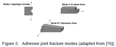
The work in [10] describes the studies of fatigue crack growth rate for two high-temperature structural adhesives named EA-9649 and AF-163 under mode I. Aluminium alloy 2024-T351 was used as the adherend, and the geometry configuration used for the specimens was a contoured double-cantilever beam. The adhesives were cured according to the manufacturer's specifications with shims to control the bond line thickness. Two plies of adhesive were used to make a 10 mm bond line and four plies of adhesive were used to make a 20 mm bond line. Crack closure loads were shown to develop as a result of fatigue crack propagation [10]. The bond lines' thickness controlled the closure load, with thicker bond lines having lower closure loads. The fatigue crack growth rates were correlated with the strain energy release rate range (ΔG) as well as with the effective strain energy release rate range (ΔGeff). The effective strain energy release rate range subtracts the strain energy release rate due to crack closure from the applied strain energy release rate range. The results showed a higher correlation between fatigue crack growth rate and ΔGeff than between fatigue crack growth rate and ΔG. The 20 mm bond line in EA-9649 was shown to have higher fatigue crack growth rates than 10 mm bond lines at equal strain energy release rate ranges. The results also showed that fatigue crack growth rates are equivalent for 10 mm and 20 mm bond lines when compared at equal effective strain energy release rate ranges.
The study discussed in [11] measured fatigue crack growth rates for an adhesive in a bond line of a double cantilever beam specimen with a cohesive crack. Bond line thickness was controlled using aluminium spacers of thickness 0.3, 0.8- and 1 mm. The joint bond line was painted with a white coating and marked at 2mm increments to assist in crack detection. The specimens were pre-cracked under a static load with a displacement control before fatigue testing. Tension-tension tests were conducted with a stress ratio of 0.5 at a frequency of 5 Hz. At least two specimens were tested for each of the bond line thicknesses. Online crack length monitoring was carried out by measuring the instantaneous compliance of the specimens using a strain compliance gauge, clipped to the specimen. The measured crack growth rate 7data for each bond line thickness was correlated with fracture resistance. The results revealed that the higher the thickness, the higher the fracture resistance. The plastic zone created around the crack tip was small enough so that it does not have any effect on the fracture property measured.
Many investigations, according to [3], have been devoted to the effect of mixed modes and the contribution of mode II in the crack growth process. The experimental investigation of adhesively bonded composite joints in [77] was conducted to characterise the crack growth mechanism under mode II. End-notched flexure joint specimens of graphite/epoxy (T300/5208) adherends bonded using EC 3445 adhesive, with an initial crack introduced by a Teflon film, were examined under static and fatigue loadings. The crack front created was at least 6 mm beyond the end of the Teflon film.
Static testing was conducted under displacement-controlled mode. The onset of crack growth, which was stable in all tests, resulted in a deviation from linearity in the recorded load-displacement curve. A custom-made clip-gage near the crack front was also used to measure accurately the critical load corresponding to the onset of the crack growth. The critical strain-energy release rate was then calculated with this measured critical load using finite element analysis. Two or more tests were done with each specimen, after each static test, the specimen was loaded until the crack grew at least 6 mm further to form a sharp crack for the next test. Fatigue testing in [77] was conducted under constant amplitude at a frequency of 2 Hz for a stress ratio of 0.1, and at a frequency of 1 Hz for a stress ratio of -1. Fatigue cycles applied loads and displacements were monitored continuously throughout each test. The measured relation between load and displacement provided the compliance, this measured compliance provided the crack length during the fatigue test from a relationship between compliance and crack length established in static testing. The crack length was measured indirectly during fatigue loading since it was difficult to monitor crack growth during the test. The experiments revealed that the critical strain energy release rates for mode I, mixed mode I-II and mode II are equal for the examined adhesive. The crack growth resistance of the joints tested at R=-1 was drastically reduced when compared to the joints tested at R = 0.1.
In the work done on [78], fatigue crack growth tests were carried out on adhesively bonded compact tension-shear specimens to investigate the behaviour of structural adhesive under mixed mode I/II conditions. The adhesive used was Loctite Multibond 330. The experiments revealed that there was an increase in crack growth rate from mode I to mode II for a given range of strain energy release rates. The study in [79] investigated the propagation of an interface crack subjected to mixed mode I/II for two thin 2024-T351 aluminium layers joined using DP760 epoxy adhesive. An analytical expression for computing the strain energy release rate was presented for the mixed-mode test. This strain energy release rate was compared to a finite element analysis using the virtual crack closure technique. Several fatigue growth tests were performed in a plane bending machine to compare the experimental strain energy release rate to those of the analytical and finite element solutions. The crack growth behaviour showed stable growth followed by rapid propagation at the interface with the adhesive layer.
The fatigue threshold and slow crack growth rate behaviour for highly toughened epoxy adhesive were studied in [80], as a function of several different aspects such as the starting condition, which includes fatigue pre-crack and fillet. The experiments were performed on cracked lap shear joints manufactured from AA6061-T651 flat bars and bonded by a toughened epoxy adhesive. The experiments showed that for cohesive failure, the threshold behaviour was very similar when the failure started from a fatigue pre-crack or an uncracked fillet. However, the threshold was lower for failure in an interface between the adhesive layer and aluminium surface when the crack grew from a fatigue pre-crack. The crack initiation from a fillet at fatigue threshold loads occurred relatively quickly when compared to the time required for a crack to reach a significant length in a practical joint. Mixed-mode fatigue crack growth, at slow rates near the threshold, became progressively interfacial as the cyclic crack speed decreased.
The work done in [81] deals with the simulation of the fatigue crack growth in bonded joints by implementing a cohesive damage model in commercial software to consider the damage produced by fatigue loading. Several different approaches were proposed using the classical Paris-like power laws expressed in terms of strain energy release rate; a selection thereof is discussed and used for the mixed-mode analysis of crack growth prediction. This mixed mode of failure for the adhesive consists of both cohesive and interlaminar failure (Fibre-breakage failure). The results of the model were in very good agreement with the expected trends, indicating that the model is adequate to simulate the fatigue crack growth behaviour of bonded joints.
5.4 Crack Propagation Modelling
Several techniques have been used in the literature to monitor crack growth and measure crack length as a function of time [3]. These techniques include video microscope and magnification lenses, chirped fibre Bragg grating sensors and ultrasonic techniques. In the study discussed in [72] for instance, to monitor damage, crack, or progression the joint samples were tested until a certain number of cycles. The samples were then removed from the test machine before failure, sectioned and mounted in a resin. The samples were sectioned at different locations from the edge of the sample. The mounted sections were then progressively polished to a 1 μm finish, these sections were then examined using an Olympus BX60M microscope. The damage in the adhesive was highlighted by using dark focus filters.
Fatigue crack propagation studies are performed by identifying the relationship between a fracture parameter and crack growth rate using fracture mechanics tests [3]. Using both the back face strain measurements and fatigue testing results in [72], a graphical model was proposed which can be used to deduce the residual life of the joint in the different regions of crack progression. The normalised back face strains and maximum fatigue loads as a percentage of static failure loads were first plotted against the logarithmic number of fatigue cycles. This was further extended by relating the back face strains with the experimental crack, damage measurements and three-dimensional simulations to create a model of graphical damage progression. The paper on [82] discusses the fatigue characteristics under mixed mode I/II conditions. Fatigue tests were conducted using single-leg bending specimens bonded with composite and steel using the co-cure bonding method. The overall results obtained showed that the crack propagation rate increases with the mode II loading component.
An equation known as the Paris equation is normally used to relate crack growth rate to a fracture parameter. In the following equation, the Paris equation is used to relate crack growth rate to the fracture parameter, taken as the stress intensity factor [83]:

where a is the crack length and da/dN is the fatigue crack growth rate for load cycle N. The parameters C and m are material coefficients that can be obtained experimentally and also depend on environment, frequency, temperature, and stress ratio. The parameter ΔK is the range of stress intensity factors between maximum and minimum stress intensity. The fracture parameter most used for adhesively bonded joints is strain energy release rate (G), according to [3]. This strain energy release can be calculated from analytical solutions or finite element analysis using measured force, crack length or the rate of change in compliance. A common fatigue crack propagation curve for adhesively bonded joints is a logarithmic plot of crack growth rate (da/dN) against the maximum strain energy release rate (Gmax) over time, the plot can be illustrated as shown below in figure 6.
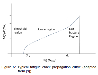
The curve in figure 6 has three regions, namely, a threshold region defined by fatigue threshold (Gth) below which no crack growth takes place, a linear or steady-state crack growth region that can be described by the Paris equation, and lastly a fast or unstable crack growth region where failure takes place as the fracture toughness Gc is reached. The crack propagation lifetime of the joint can therefore be established by the integration of the fatigue crack propagation curve if the relationship between the crack length (a) and Gmax is known.
Fatigue crack propagation in adhesively bonded joints was analysed and discussed in [84]. Three different bonded joints, which were double-cantilever beams, single-lap joints, and double-lap joints, were considered. The joints were made from carbon fibre composite substrates, bonded with an epoxy adhesive. The joints were tested in constant amplitude fatigue at different loads, and curves of loads vs. number of cycles to failure were obtained. The following crack propagation law was derived from the experimental results of the double-cantilever beam:

where P and n can be obtained by fitting the equation to the experimental data. G is the strain energy release rate, which can be determined at any crack length from finite element analysis. Two possible modes of fatigue crack were considered - opening (mode I) and sliding (mode II). The paper then suggests that G can either be the total strain energy release rate for both modes combined (GT = G1 + G11 ) or it can be the mode I strain energy release rate ( G1). The number of cycles to failure (Nf ) can therefore be determined by integrating the equation from the initial crack size (a0) to final crack size (af) as:

The above model was implemented in a finite element-based predictive tool to predict the number of cycles to failure for single-lap and double-lap joints subjected to cyclic fatigue loading. A generalise numerical procedure using finite element analysis for prediction of the fatigue lifetime of adhesively bonded structures was proposed in [85]. The number of cycles to failure was determined by integrating a fatigue crack growth law between the initial and final crack length. This crack law was formulated in terms of the strain energy release rate, determined at any crack length from finite element (FE) analysis. The complete process was implemented with FE code, enabling automated calculation of the fatigue life for a given set of boundary conditions. The procedure was evaluated by application to a single lap joint and good results were obtained in comparing with those using other methods.
A general method for the prediction of fatigue crack propagation lifetime in bonded structures by using finite element analysis was suggested in [86]. The method is based on the numerical integration of the fatigue crack growth law from an initial to a final crack size. The model was applied to CFRP joints bonded with epoxy adhesive. Crack growth law was established experimentally using double cantilever beam samples. Experimental load-life data were also established for single and double lap joints using the same material. The crack growth law determined from double cantilever beam specimens was then used to predict the load-life response of the single and double lap joints, good agreement was observed between the experiments and predicted load-life plots.
A bi-linear traction separation description of a cohesive zone model was employed to simulate progressive damage in the adhesively bonded joints for the work done in [87]. Experimental tests on coupons cut from a bonded panel and separately manufactured single-lap joints were undertaken to obtain model parameters. The finite element model was developed in ABAQUS code under static and fatigue loading. Four-node cohesive elements with bi-linear traction-separation descriptions were used. The proposed model gave a consistent match with experimental fatigue response in terms of life, back-face strain, and predicted damage growth.
5.5 Summary
The developments of new and more adhesives such as an in-house produced adhesive discussed in section 2.2 therefore create a knowledge gap in fatigue behaviour in terms of understanding how crack initiates and propagates in these adhesives. These new developments and research opportunities can therefore assist in the identification of adhesives that provide bonded joints with long fatigue life, i.e., those with better failure initiation and delayed propagation to final failure. Crack initiation and propagation in this regard can play an important role in the characterisation of the adhesive and consequently in the qualification and certification of the adhesively bonded joint parts. More behavioural characteristics of these new conditions on fatigue behaviour of adhesively bonded parts constituting these adhesives are some of the knowledge gaps that can be filled by the experimental studies.
6 Environmental Conditions
Bonded joints may be exposed to various environmental conditions in their service [4]. The performance of the adhesive system can be considerably reduced when exposed to harsh environments according to [3], it is stated that an adhesive joint loses its strength and fatigue resistance when it is exposed to hostile environment conditions. Environmental conditions that can affect the properties of an adhesively bonded joint can therefore affect the ultimate mechanical performance of the joint [4]. These conditions should be considered critical in determining the long-term durability of the bonded joints and need to be identified and related to the type of service the material will expose to.
The main environmental conditions in climate exposure are temperature and humidity according to [4]. An example is the study in [88] which investigated the fatigue response of adhesively bonded pultruded GFRP double lap joints under different temperatures and relative humidities. The tests were performed at -350C, 230C and 400C. Fatigue data was also collected from tests on preconditioned specimens in warm water at 400C. The tests were conducted at 40% and 90% relative humidity. The specimens were instrumented with strain and crack initiation gages to record data, S-N curves, stiffness fluctuations and crack initiation and propagation were observed. The fibre-tear failure that occurred in the mat layers of the GFRP laminate was the dominant failure mode. The failure shifted to the adhesive/composite interface in the presence of humidity. The influence of temperature on the fatigue life and fracture behaviour was apparent and aggravated due to the presence of humidity, even though the testing temperature was lower than the glass transition temperature of the adhesive. The effect of these two conditions on the fatigue behaviour of adhesively bonded joints is thus further discussed in the following two parts. The last part then closes the section with some comments.
6.1 Temperature
Several authors have studied the effect of temperature on the fatigue performance of adhesively bonded composite joints. The work in [89] investigated double lap joints under both static and fatigue across temperature ranges experienced by jet aircraft. The tests were conducted at temperatures of -500C, 220C and 900C at ambient humidity. Two variants on the double lap joints were made for testing, one with multidirectional (MD) CFRP adherends and another one with unidirectional (UD) CFRP adherends. Finite element analysis was used to analyse stresses in the joints. The adhesive used was based on a di-glycidyl ether of bisphenol A epoxy, crosslinked with a primary amine curing agent and toughened with a reactive liquid polymer based on carboxyl-terminated butadiene acrylonitrile rubber. The adhesive also contained silica filler.
Both static and fatigue testing in [89] were conducted using a machine fitted with temperature chambers, computerised control, and data logging. Static tests were carried out under displacement control with a ramp rate of 1 mm/minute, with five repetitions of each test. Fatigue testing was performed in load control, using a constant amplitude and frequency of 5 Hz at a stress ratio of 0.1. The fatigue tests were carried out at several different loads to construct the maximum load against the number of cycles curves. The experimental results showed that as the temperature increases, both static strength and fatigue resistance decreased. The MD joints were stronger at low temperatures and the UD joints were stronger at high temperatures. This was because at low temperatures the strength was determined by the peak stresses in the joints, while it was controlled by the creep of the joints at high temperatures.
The fatigue behaviour of two adhesives intended to be used in automotive bodyshell construction was investigated using simple load shear test pieces in the work done in [90]. Single lap joints consisting of adherends made from mild steel conforming to BS1449: CR1E. Two adhesives with different chemical types were selected, polybutadiene adhesive named elastosol M51 as well as the flexible toughened epoxy adhesive called XW1012. Static and fatigue lives were measured over a range of adhesive layer thicknesses and test temperatures for both adhesives. Static testing was conducted with a temperature-controlled cabinet at a constant displacement rate of 1 mm/min, these tests were done at three adhesive thicknesses of 0.2 mm, 0.9 mm, and 2 mm as well as temperatures of -300C, 200C and 900C for each adhesive.
Fatigue testing in [90] was conducted under force control, cyclic loads were applied between zero and a maximum. Joints with adhesive layer thicknesses of 0.2 mm and 2 mm were tested for the second adhesive. Joints with an adhesive layer thickness of 2mm were tested for the first adhesive at temperatures of -300C, 200C and 900C. A frequency response analyser (FRA) was used to control the required amplitude and to perform dynamic property measurements. The FRA was controlled using an IBM computer to record the dynamic properties of the test joint during fatigue tests. The measurements including the change in stiffness and loss angle during fatigue loading were used as means of detecting the initiation and propagation of fatigue cracks. The experimental results showed that over a wide range of temperatures that included the glass transition temperature, fatigue life in both adhesives was dominated by a crack initiation phase. The results also revealed that joints with thinner adhesive layers were stronger and more fatigue resistant. The joint strength and fatigue resistance was reduced outside the glass region of the adhesives. The paper then recommended that the glass transition temperature of the adhesive should be above the maximum temperature expected in service for load-bearing applications.
The work in [91] experimentally investigated the tension-tension fatigue behaviour of ductile adhesively bonded double-lap fibre-reinforced polymer (FRP) joints. Fatigue degradation of the joints was characterised by cyclic energy dissipation, cyclic stiffness, cyclic creep displacement and self-generated temperature. The effects of elevated temperature on the joints' static tensile and pure creep behaviours were also studied. Basalt FRP laminates were used as adherends in the double-lap joint configuration. A ductile acrylic adhesive named ADP, which is in the rubber state at ambient temperature, was used for bonding. The experiments showed that all joints failed in the adhesive layer at almost the same failure displacement, independent of whether the loading was static, creep, fatigue, or temperature loading. The experiments also revealed that fatigue failure was driven by cyclic creep; cyclic creep displacements were accelerated mainly by the damage caused by fatigue at high loads and by the damage caused by creep and self-generated temperature.
The work in [92] studied the effect of temperature on the mechanical properties of adhesively bonded basalt FRP-aluminium alloy (BFRP-Al) joints. The adhesive selected for the study was Araldite 2015, which is a two-component epoxy adhesive widely used in the automotive industry. The adhesive was used to fabricate bulk tensile specimens, butt joints, scarf joints with angles of 450 as well as thick adherend shear joints. For convenience, a butt joint was also used for the shear test and therefore identified as a thick adherend shear joint. A shear-loading device for the butt joint was also used to determine the shear stress of the adhesive. Five temperatures of -40, -10, 25, 50 and 80 0C were selected for testing the joints. A differential scanning calorimetry analysis of the Araldite 2015 and BFRP was performed, and the strain of bulk specimens at different temperatures was obtained using 3D digital image correlation methods. The results from the tests showed that as the temperature increased, Young's modulus and tensile strength of the Araldite 2015 increased. The tensile strain increased, and the mechanical properties changed significantly as the glass transition temperature approached or exceeded. The results also revealed that the failure strength of the BFRP-Al joints at different temperatures was influenced by the performance of the adhesive and the BFRP, while the strength decreased at elevated temperatures. The shear tests revealed that the shear load capacity of the BFRP-Al joints was the highest and that the joints were more likely to fail under normal stress as well as under combined shear and normal stress.
The temperature effects on the static and fatigue characteristics of adhesively bonded tubular single-lap joints were investigated in [93].
An outer steel (SM45C) adherend and an inner steel were bonded with epoxy adhesive. Two types of rubber-toughened structural epoxy adhesives, namely IPCO 9923 and Araldite AV138-HV998, were used. Torsional static and torsional fatigue tests were performed on the joints by varying the environmental temperature between 25, 30, 40 and 60 0C. The relations between the parameters of the stress-life curves and the static strength of adhesively bonded tubular single-lap joints were obtained. A fatigue life prediction model was then developed for the joints at elevated temperatures.
The work in [94] compared the fatigue crack growth characteristics of adhesively bonded joints at saturated at several temperatures in air and salt water. A modified cracked lab shear configuration under four-point bending was used to load the specimens, which were reinforced to ensure that cracking at or near the interface could be examined under all conditions. Paris law parameters and threshold values of energy release rate were extracted for each environmental condition studied. Both high and low temperatures in the air increased crack growth rates and reduced threshold values relative to room temperature. Increasing the temperature from 100C consistently decreased the bond durability in salt water. The paper then related the effects of load level, temperature, and environment on the fracture parameters with fracture mechanisms using recorded side views and fractographic evidence.
6.2 Humidity
The presence of moisture in adhesive joints may weaken the interface between the adhesive and the substrate, in addition to weakening the physical and chemical properties of the adhesive [4]. Bonded joints can be exposed to moisture through ageing in humidity or distilled water, and then be tested under fatigue loads to investigate the effect of humidity on the fatigue strength of the joints [3]. Many authors have studied the effect of humidity on the fatigue behaviour of adhesively bonded joints. The paper in [95] discusses the effect of moisture on the static and fatigue resistance of adhesively bonded laminate joints. The experimental testing was carried out on both aged and unaged bonded laminate joints under static and fatigue loading. The tests were done in three different joint configurations, doublers (DB) for three-point bending, full-width single-lap joints (FSLJs) and reduced-width single-lap joints (RSLJs). These joints were cut from the bottom skin of a potential wing panel that was manufactured using Al 2043-T3 and a rubber-toughened epoxy adhesive FM73. The joints were exposed to laboratory ageing conditions by immersing in the de-ionised water at a constant temperature of 500C to accelerate the ageing process.
Static tests in [95] were performed on both unaged and aged joints to determine the effect of moisture on static strength. DB joints were examined under three-point bending at a rate of 0.5 mm/min for both unaged and aged (after 360 days) conditions. The FSLJs and RSLJs were tested under tensile load at a rate of 0.1 mm/min for unaged and aged (after 360 and 720 days) conditions. Fatigue testing was also conducted on unaged and aged conditions, and load-life curves were obtained. The tests were performed under room temperature using a sinusoidal load-controlled condition at a load ratio of 0.1 and frequency of 5 Hz.
The DB joints were tested in a three-point bending for unaged and aged (after 360 days) conditions at different load levels while both FSLJs and RSLJs were tested in tensile fatigue loading for unaged and aged (after 360 and 720 days) conditions at different load levels. The results showed that a considerable reduction of up to 15% in static strengths of all the joints examined was observed when exposed to de-ionized water at 500C constant temperature for 2 years. The observed failure mode in both unaged and aged conditions was predominantly cohesive. A reduced fatigue response was also observed when the joints were exposed to the de-ionised water at 500C constant temperature. The horizontal shift in the curves of the load life was noticed with increasing exposure time. Using a cohesive zone approach for the adhesive bond line, a combined diffusion-stress analysis was developed to predict the progressive damage experimentally observed in the joints. The predictions were found to be in good agreement with the experimental test result values.
The work in [96], as another example, investigated the cyclic fatigue behaviour of adhesively bonded joints that consisted of aerospace-grade epoxy adhesive, which was used to bond aluminium alloy substrates. The specimen configuration used for the test samples was a tapered double-cantilever beam. The joints were tested under fatigue tests in a dry environment of 23 ± 1 0C and 55% relative humidity, as well as a wet environment of immersion in distilled water at 28 ± 1 0C. The tests were used to obtain the relationship between the rate of fatigue crack growth per cycle and the maximum strain energy release rate applied during the fatigue cycle. The effect of using various surface pre-treatments for the substrates before bonding was also investigated. X-ray photoelectron spectroscopy as well as electron microscopy techniques were used to identify the locus of joint failure and the mechanism of environmental attack.
The wet cyclic fatigue tests in [96] revealed the presence of a threshold value for the strain-energy release rate, below which crack growth was found not to occur. This threshold value provides a quantitative measure of the effectiveness of a given surface pre-treatment in an aqueous environment. The role of the interphase is crucial in determining the durability of the joints. The X-ray and electron microscopy techniques revealed that the joints experiencing the poorest durability failed in the adhesive/oxide interphase. The locus of joint failure arising from wet cyclic-fatigue loading was along the adhesive/oxide interface for the grit blast followed by degreasing (GBD) pre-treated joints. The locus of joint failure was through the oxide layer for the phosphoric acid anodising pre-treated joints.
The work of [ [97]], for example, investigated the effect of elevated humidity levels on the fatigue and failure behaviour of an electrically conductive adhesive called Ablebond MA-2. Single-lap joint specimens consisting of this adhesive and stainless steel 304 adherends were tested under monotonic and cyclic fatigue conditions. The specimens were tested under three different load ratios of R = 0.1, R = 0.5 and R = 0.9 as well as at two relative humidity levels of 20% and 90%, all tests were done at the temperature of 28 0C. The failure mechanisms in the joint were analysed using optical techniques and joint conductivity. The experiments showed that the load versus number of cycles were parallel, and the failure modes were predominantly interfacial, accompanied by a significant decrease in joint conductivity.
The paper in [98] analysed the fatigue delamination and fracture stress behaviour under mode I of adhesive joints composed out of epoxy matrix composite materials with unidirectional CFRP and commercial epoxy-based called Loctite EA 9461. Double cantilever beam specimen joint configuration was used to quantify the influence that exposing the joints to a saline environment has on fatigue behaviour. The composite adherend was surface prepared by manual abrasive sanding with AL2O3 sandpaper and grain P220. A 12 μm thick Teflon PTFE film was placed between the substrate's adherends at one end of the specimen to act as a 50 mm crack initiator of the delamination process.
The objective of using the degradation process, which is the saline environment consisting of a salt spray chamber for this work, was to evaluate the quality of the adhesive joint subjected to the exposure time in different external agents generated in the process. These agents included humidity, temperature, and salt concentrations. The levels of the energy release rate to be applied in the fatigue testing and exposure period times were defined together with a stress ratio of 0.1, defined as the ratio between minimum and maximum energy release rates. Energy release rates-cycles fatigue initiation curves as well as energy releases rates-crack growth rates curve were plotted from the experimental data. The main relevant result from this paper was that the fatigue limits of the adhesive do not translate into a relevant loss of its resistance to fatigue delamination under mode-I loading. The crack growth rates of the joints subjected to different periods of exposure to a saline environment are similar and higher than those obtained for the joints without exposure.
The work in [99] assessed the fatigue performance of adhesive joints immersed in different solutions. Two types of single-lap joints were used for test specimens - one where both adherends were aluminium alloy and one where both adherends were pure casts of Polymethyl methacrylate. The adhesive used in both types of joints was a two-part epoxy, consisting of AW106/HV953U and CIBA-GEIGY. The joint specimens were immersed in distilled water and saline water at different temperatures and subjected to different sinusoidal tensile loads. The joints were also tested in the air. The experimental results showed that the fatigue life of the bonded joints decreased with an increase in the temperature of the solution or load level. The Polymethyl methacrylate joints showed better fatigue performance both in distilled water and saline water than in air, while the aluminium joints showed better fatigue performance in air.
The work in [100] discusses an experimental study on the interfacial of CFRP-steel double lap bonded joints subjected to salt fog spray at the curing stage. The adhesive used in the study was Araldite 420. The examined joint samples after the curing stage were subjected to a pre-set number of fatigue cycles followed by static testing to failure. The bond strength loss of the joints ranged from 1% to 11% after environmental exposure and fatigue loading. The effects on the elastic modulus and ultimate strain were comparable to that of long-term exposure to a well-cured adhesive.
6.3 Summary
The studies above, therefore, indicate that the service environmental conditions can be simulated in terms of temperature and humidity to evaluate environmental impacts on the fatigue behaviour of adhesively bonded joints. The behaviour of the adhesive used in those joints can thus be also characterised in terms of these two parameters. More adhesives can then be investigated using these parameters, therefore also contributing to the adhesive selection process discussed in section 2.
7 Conclusions
This paper reviewed the fatigue behaviour of adhesives and joints used in composite structures. The bonded joints are therefore critical parts of composite structures. The topics discussed are structural adhesives in bonded joints, experimental fatigue testing, fatigue strength and fatigue life, crack initiation and crack propagation as well as environmental conditions. Experimental investigations into the fatigue behaviour of samples of bonded composite joints, which are performed using parameters, testing standards and test data precision methods discussed in this paper will therefore provide an insight into fatigue characterisation for bonded composite parts as well as adhesive systems constituting these parts. These investigations into the fatigue behaviour of adhesives used in composite structural bonding applications are therefore ongoing research work. This is because a wide variety of adhesives exist or are currently being developed. The following additional conclusions are drawn from this review.
Experimental research into fatigue behaviour for a particular adhesive used in composite structure should therefore consist of experimental testing of adhesively bonded joint samples made out of the composite adherends and bonded using that specific adhesive. Various conditions exist in terms of adhesive system composition, geometry configuration, adherends surface treatment, as well as various fatigue loading conditions for bonded composite joint parts. The fatigue behaviour should therefore first be characterised by such experimental testing by investigating the impact of these various aspects on fatigue strength and fatigue life of the bonded joints and consequently of the adhesive examined. Crack initiation and propagation due to fatigue loading are therefore other topics of interest for experimental investigations into the behavioural characterisation of adhesives. Composite adhesively bonded joint samples consisting of the adhesive of interest should therefore be used in the fracture studies to understand a proportion of the fatigue life spent in both initiation and propagation of failure for the joint and adhesive. Damage models in the bonded joints are some of the tools that can be used to characterise the fatigue fracture behaviour of the adhesive. Various techniques of monitoring and detecting crack initiation in the bonded joints should therefore be investigated and developed for better experimental accuracy and reliability. The three various crack opening modes should be considered in these fracture studies to understand the rates of crack growth for these components. Crack initiation and crack propagation models are other tools that can be used in simulating the initiation and propagation behaviour of the cracks under fatigue loading.
The fatigue behaviour characterisation of adhesives should also, therefore, be expressed in terms of the actual service conditions that the adhesive will operate under. Composite bonded joints of the specific adhesive should therefore be experimentally investigated under simulated actual conditions that consist of various temperatures and humidities. The effect of these environmental conditions on the fatigue behaviour of the bonded joints and the adhesive will be the result of such investigations.
References
[1] R. Sarfaraz, A. P. Vassilopoulos and T. Keller, "Experimental Investigation of the Fatigue Behaviour of Adhesivley-Bonded Pultruded GFRP Joints Under Different Load Ratios," International Journal Of Fatigue, vol. 33, pp. 1451-1460, 2011. [ Links ]
[2] C. Katsiropoulos, A. Chamos, K. Tserpes and S. Pantelakis, "Fracture toughness and shear behavior of composite bonded joints based on a novel aerospace adhesive," Composites: Part B, vol. 43, pp. 240-248, 3 July 2011. [ Links ]
[3] M. A. Wahab, "Fatigue In Adhesively Bonded Joints: A Review," International Scholarly Research Network, vol. 2012, p. 25, 03 October 2012. [ Links ]
[4] M. Banea and L. Da Silva, "Adhesively Bonded Joints In Composite Materials: An Overview," Proc. IMechE: J. Materials: Design And Applications, vol. 223, p. 18, 2008. [ Links ]
[5] AMTS, "AMTS Standard Workshop Practice: Adhesive Bonding," Technology Innovation Agency, 2011.
[6] A. Pirondi and G. Nicoletto, "Fatigue crack growth in bonded DCB specimens," Engineering Fracture Mechanics, vol. 71, pp. 859-871, 2004. [ Links ]
[7] R. R. Gotman and E. Sancaktar, "A comprehensive fatigue life predictive model for electronically conductive adheisve joints under constant-cycle loading," Journal Of Adhesion Science And Technology, vol. 20, pp. 87-104, 16 October 2005. [ Links ]
[8] H. Corporation, "Loctite Ablestik MA 2," Henkel Corporation, Dusseldorf, 2014.
[9] I. A. Ashcroft, J. P. Casa-Rodriguez and V. V. Silberschmidt, "A model to predict the anomalous fatigue crack growth behaviour seen in mixed mechanism fracture," The Journal Of Adhesion, vol. 86, pp. 522-538, 2013. [ Links ]
[10] D. A. Jablonski, "Fatigue crack growth in structural adhesives," The Journal Of Adhesion, vol. 11, pp. 125-143, 2007. [ Links ]
[11] M. Abou-Hamada, M. Megahed and M. Hammouda, "Fatigue crack growth in doublecantilever beam specimen with an adhesive layer," Engineering Fracture Mechanics, vol. 60, pp. 605-614, 1998. [ Links ]
[12] Y.-M. Jen, "Fatigue life evaluation of adhesivey bonded scarf joints," International Journal Of Fatigue, vol. 36, pp. 30-39, 2012. [ Links ]
[13] G. Meneghetti, M. Quaresimin and M. Ricotta, "Influence of the interface ply orientation on the fatigue behviour of bonded joints in composite materials," International Journal Of Fatigue, vol. 32, pp. 82-93, 2010. [ Links ]
[14] 3M Science Applied to Life, "3M Science Applied to Life," 3M Science Applied to life, 2017. [Online]. Available: https://www.3m.com. [Accessed 26 October 2022].
[15] M. R. Ayatollahi and A. Akhavan-Safar, "Failure load prediction of single lap adhesive joints based on a new linear elastic citerion," Theoretical And Applied Fracture Mechanics, vol. 80, pp. 210-217, 2015. [ Links ]
[16] X. X. Xu, A. D. Crocombe and P. A. Smith, "Fatigue crack growth rates in adhesive joints tested at different frequencies," The Journal Of Adhesion, vol. 58, pp. 191-204, 1996. [ Links ]
[17] AMTS, "AMTS Standard Workshop Practice: Bonding and filling using laminating epoxy," Technology Innovation Agency, 2008.
[18] Hexion Specialty Chemicals, "Laminating resin MGS® L 285," Hexion Speciality Chemicals, Stuttgart, 2006.
[19] B. Harris, Fatigue In Composites, Cambridge: Woodhead Publishing Limited, 2003. [ Links ]
[20] ISO, "Fibre-reinforced plastics - Determination of fatigue properties under cyclic loading conditions," ISO, Geneva, 2003.
[21] J. Devore, N. Farnum and J. Doi, Applied Statistics for Engineers and Scientists, Stamford, Connecticut Turnpike: CENGAGE Learning, 2013. [ Links ]
[22] ASTM, "Standard Test Method for Tension-Tension Fatigue of Polymer Matrix Composite Materials," ASTM International, West Conshohocken, PA, 2002.
[23] A. P. Vassilopoulos, Fatigue And Fracture Of Adhesively-Bonded Composites Joints, Cambridge: Woodhead Publishing, 2015. [ Links ]
[24] ASTM, "Standard Test Method for Fatigue Properties of Adhesives in SHear by Tension Loading (Metal/Metal)," ASTM, West Conshohocken, PA, 1999.
[25] ASTM, "Standard Test Method for Lap Shear Adhesion for Fiber Reinforced Plastic (FRP) Bonding," ASTM International, West Conshohocken, PA, 2001.
[26] ASTM, "Apparent Shear Strength of Single-Lap-Joint Adhesively Bonded Metal Specimens by Tesnion Loading (Metal-to-Metal)," ASTM International, West Conshohocken, PA, 2011.
[27] ISO, "Adhesives - Test methods for fatigue properties of structural adhesives in tensile shear," ISO, Geneva, 1993.
[28] ISO, "Adhesives - Durability of structural adhesive joints -Exposure to humidity and temeoerature under load," ISO, Geneva, 1997.
[29] ISO, "Fibre-reinforced plastic composites - Determination of mode I interlaminar fracture toughness, Gic, for undirectionally reinfoced materials," ISO, Geneva, 2001.
[30] ISO, "Accuracy (trueness and precision) of measurement methods and results-Part 4: Basic methods for the determination of the trueness of a standard measurement method," ISO, Geneva, 2020.
[31] ASTM, "Standard Practice for Conducting an Interlaboratory Study to Determine the Precision of a Test Method," ASTM International, West Conshohocken, PA, 2019.
[32] B. N. Taylor and C. E. Kuyatt, "Guidelines For Evaluating And Expressing The Uncertainty Of NIST Measurement Results," NIST, Gaithersburg, 1994.
[33] R. C. Juvinall and K. M. Marshek, Fundamentals Of Machine Component Design, Asia: John Wiley & Sons, 2006. [ Links ]
[34] C. W. Kensche, Fatigue Of Materials And Components For Wind Turbine Rotor Blades, Luxembourg: EUROPEAN COMMISSION, 1996. [ Links ]
[35] C. R. Mischke, J. E. Shigley and R. G. Budynas, "Introduction To Fatigue In Metals," in Mechanical Engineering Design, 7th ed., J. P. Holman and J. R. Lloyd, Eds., New York, McGraw-Hill, 2004, pp. 306-307.
[36] J.-P. Jeandrau, C. Peyrac, F. Lefebvre, J. Renard, V. Gantchenko, B. Patamaprohom and C. Guinault, "Fatigue behaviour of adhesive joints," in 6th Fatigue Design conference, Fatigue design, Paris, 2015.
[37] S. Razavi, E. S. Bale and F. Berto, "Mechanical behavior of metallic fiber-reinforced adhesive under cyclic loading," in The 1st Mediterranean Conference on Fracture and Structural Integrity, Trondheim, Norway, 2020.
[38] S. M. Khalili, A. Shokuhfar, S. D. Hoseini, M. Bidkhori, S. Khalili and R. K. Mittal, "Experimental study of the influence of adhesive reinforcement in lap joints for composite structures subjected to mechanical loads," International Journal Of Adhesion & Adhesion, vol. 28, pp. 436-444, 2008. [ Links ]
[39] M. J. Hoke, "Adhesive Bonding Of Composites," Abaris Training Inc, Nevada, 2005.
[40] T. Yu, D. Fernando, J. Teng and X. Zhao, "Experimental study on CFRP-to-steel bonded interfaces," Composites: Part B, vol. 43, pp. 2279-2289, 2012. [ Links ]
[41] Y. Zhang, A. P. Vassilopoulos and T. Keller, "Stiffness degradation and fatigue life prediction of adhesively-bonded joints for fibre-reinforced polymer composites," International Journal Of Fatigue, vol. 30, pp. 1813-1820, 2008. [ Links ]
[42] Y.-M. Jen and C.-W. Ko, "Evaluation of fatigue life of adheisvely bonded aluminum single-lap joints using interfacial parameters," International Journal Of Fatigue, vol. 32, pp. 330-340, 2009. [ Links ]
[43] Q.-G. Zeng and C. T. Sun, "Novel design of a bonded lap joint," AIAA Journal, vol. 39, pp. 1991-1996, 2001. [ Links ]
[44] Y.-M. Jen, "Fatigue life evaluation of adhesively bonded scarf joints," International Journal Of Fatigue, vol. 36, pp. 30-39, 2012. [ Links ]
[45] G. Altan, M. Topcu and H. Callioglu, "The effects of the butterfly Joints on failure loads and fatigue performance of composite structures," Science And Engineering Of Composites Materials, vol. 17, pp. 199-212, 2010. [ Links ]
[46] L. F. Da Silva, N. Ferreira, V. Richter-Trummer and E. Marques, "Effect of grooves on the strength of adhesively bonded joints," International Journal Of Adhesion & Adhesives, vol. 30, pp. 735-743, 2010. [ Links ]
[47] S. Azari, M. Papini and J. Spelt, "Effect of surface roughness on the performance of adhesive joints under static and cyclic Loading," The Journal Of Adhesion, vol. 86, pp. 742-764, 2010. [ Links ]
[48] M. Davis and D. Bond, "Principles and practices of adhesive bonded structural joints and repairs," International Journal Of Adhesion & Adhesives, vol. 19, pp. 91-105, 1999. [ Links ]
[49] P. Molitor, V. Barron and T. Young, "Surface treatment of titanium for adhesive bonding to polymer composites: a review," International Journal Of Adhesion & Adhesives, vol. 21, pp. 129-136, 2001. [ Links ]
[50] S. Azari, M. Papini, J. A. Schroeder and J. K. Spelt, "The effect of mode ratio and bond interface on the fatigue behaviour of a highly-toughened epoxy," Engineering Fracture Mechanics, vol. 77, pp. 395-414, 2010. [ Links ]
[51] I. Bello, Y. Alowayed , J. Albinmousa, G. Lubineau and N. Merah, "Fatigue crack growth in laser-treated adhesively bonded composite joints: an experimental examination," International Journal Of Adhesion And Adhesives, vol. 105, pp. 1-23, 2021. [ Links ]
[52] W.-S. Kim and J.-j. Lee, "Adhesion strength and fatigue life improvement of co-cured composite/metal lap joints by silane-based interphase formation," Journal Of Adhesion Science And Technology, vol. 21, pp. 125-140, 2007. [ Links ]
[53] E. Knox, M. Cowling and S. Hashim, "Fatigue performance of adhesively bonded connections in GRE pipes," International Journal Of Fatigue, vol. 22, pp. 513-519, 2000. [ Links ]
[54] R. Sarfaraz, A. P. Vassilopoulos and T. Keller, "Experimental investigation and modeling of mean load effect on fatigue behaviour of adhesively-bonded pultruded GFRP joints.," International Journal Of Fatigue, vol. 44, pp. 245-252, 2012. [ Links ]
[55] G. K. Boerstra, "The multislope model: A new description for the fatigue strenght of glass fibre reinforced plastic," 10 February 2006. [Online]. Available: www.wmc.eu. [Accessed 10 February 2006].
[56] M. Kawai and M. Koizumi , "Nonlinear constant fatigue life diagrams for carbon/epoxy laminates at room tempearture," Composites: Part A, vol. 38, pp. 2342-2353, 7 Januray 2007. [ Links ]
[57] A. P. Vassilopoulos*, B. D. Manshadi and K. Thomas, "Influence of the constant life diagram formulation on the fatigue life prediction of composite materials," International Journal of Fatigue, vol. 32, pp. 659-669, 2010. [ Links ]
[58] M. Sharverdi, A. P. Vassilopoulos and T. Keller, "A total fatigue life model for the prediction of the R-ratio effects on fatigue crack growth of adhesively-bonded pultruded GFRP DCB joints," Composites: Part A, vol. 43, pp. 1783-1790, 2012. [ Links ]
[59] I. Ashcroft and S. J. Shaw, "Mode I fracture of epoxy bonded composite joints 2. Fatigue loading," International Journal of Adhesion & Adhesives, vol. 22, pp. 151-167, 2002. [ Links ]
[60] J. Schijve, Fatigue Of Structures And Materials, Delft: Springer, 2009. [ Links ]
[61] I. Cerny and R. M. Mayer, "Fatigue of selected GRP composite components and joints with damage evaluation," Composite Structures, vol. 94, pp. 664-670, 2012. [ Links ]
[62] R. S. Khabbaz, "Fatigue life prediction of adhesively-bonded fiber-reinforced polymer structural joints under spectrum loading patterns," À La Faculte De L'environement Naturel, Architectural Et Construit, Suisse, 2012.
[63] V. A. Passipoularidis, T. P. Philippidis and P. Brondsted, "Fatigue life prediction in composites using progressive damage modelling under block and spectrum loading," International Journal Of Fatigue, vol. 33, pp. 132-144, 2011.
[64] A. G. Solana, A. D. Crocombe and I. A. Ashcroft, "Fatigue life and backface strain predictions in adhesively bonded joints," International Journal Of Adhesion & Adhesives, vol. 30, pp. 36-42, 2010. [ Links ]
[65] V. Shenoy, I. A. Ashcroft, G. W. Critchlow and A. D. Crocombe, "Unified methodology for the prediction of the fatigue behaviour of adhesivley bonded joints," International Journal Of Fatigue, vol. 32, pp. 1278-1288, 2010. [ Links ]
[66] B. Pan, K. Qian, H. Xie and A. Asundi, "Two-dimensional digital image correlation for in-plane displacement and strain measurement: a review," Measurement Science And Technology, vol. 20, pp. 1-17, 2009. [ Links ]
[67] E. C. Kavdir and M. D. Aydin, "The experimental and numerical study on the mechanical behaviours of adhesively bonded joints," Composites: Part B, pp. 1359-8368, 2020.
[68] Y. Pang, G. Wu, H. Wang and Y. Liu, "Interfacial bond-slip degradadation relationship between CFRP plate and steel plate under freeze-thaw cycles," Construction And Building Materials, vol. 214, pp. 242-253, 2019. [ Links ]
[69] H.-T. Wang , G. Wu, Y.-T. Dai and X.-Y. He, "Experimental study on bond behaviour between CFRP plates and steel using digital Image correlation," Journal of Composites for Construction, pp. 1-12, 2016.
[70] H.-T. Wang, G. Wu, Y.-Y. Pang, J.-W. Shi and H. M. Zakari, "Experimental study on the bond behaviour between CFRP plates and steel substrates under fatigue loading," Composites: Part B, vol. 176, pp. 1359-8368, 2019. [ Links ]
[71] B. Ghiassi, J. Xavier, D. V. Oliveira and P. B. Lourenco, "Application of digital image correlation in investigating the bond between FRP and masonry," Composite Structures, vol. 106, pp. 340-349, 2013. [ Links ]
[72] V. Shenoy, I. A. Ashcroft, G. W. Gritchlow, A. D. Crocombe and A. M. Wahab, "An investigation into crack initiation and propagation behaviour of bonded single-lap joints using backface strain," International Journal Of Adhesion & Adhesives, vol. 29, pp. 361-371, 2009. [ Links ]
[73] Z. Zhang, J. K. Shang and F. V. Lawrence Jr, "A Backface Strain Technique for Detecting Fatigue Crack Initiation in Adhesive Joints," The Journal Of Adhesion, vol. 49, pp. 23-26, 1995. [ Links ]
[74] G. Meneghetti, M. Quaresimin and M. Ricotta, "Damage mechanism in composite bonded joints under fatigue loading," Composites: Part B, vol. 43, pp. 210-220, 2012. [ Links ]
[75] M.-H. Kang, J.-H. Choi and J.-H. Kweon, "Fatigue life evaluation and crack detection of the adhesive joint with carbon nanotubes," Composite Structures, vol. 108, pp. 417-422, 2014. [ Links ]
[76] F. J. Chaves, L. Da Silva, M. De Moura, D. Dillard and V. Esteves, "Fracture Mechanics Tests in Adhesively Bonded Joints: A Literature Review," The Journal Of Adhesion, vol. 90, p. 955-992, 2014. [ Links ]
[77] S. Mall and N. Kochhar, "Characterisation of debond growth mechanism in adhesively bonded compistes under mode II static and fatigue loading," Engineering Fracture Mechanics, vol. 31, pp. 747-758, 1988. [ Links ]
[78] A. Pirondi and G. Nicoletto, "Mixed Mode I/II fatigue crack growth in adhesive joints," Engineering Fracture Mechanics, vol. 73, pp. 2557-2568, 2006. [ Links ]
[79] G. V. Marannano, L. Mistretta, A. Cirello and S. Pasta, "Crack growth analysis at adhesive-adherent interface in bonded joints under mixed mode I/II," Engineering Fracture Mechanics, vol. 75, pp. 5122-5133, 2008. [ Links ]
[80] S. Azari, M. Papini, J. A. Schroeder and J. K. Spelt, "Fatigue threshold behaviour of adhesive joints," International Journal Of Adhesion & Adhesives, vol. 30, pp. 145-159, 2010. [ Links ]
[81] A. Pirondi and F. Moroni, "A procedure for the simulation of fatigue crack growth in adhesivley bonded joints based on the cohesive zone model and different mixed-mode propagation criteria," Engineering Fracture Mechanics, vol. 78, pp. 1808-1816, 2011. [ Links ]
[82] S.-H. Baek, W.-S. Kim, C.-J. Jang and J.-J. Lee, "Mixed-mode fatigue characteristics of composite/metal interfaces," Key Engineering Materials, Vols. 452-453, pp. 437-440, 2011. [ Links ]
[83] D. Roylance, "Fatigue," Massachusetts Institute of Technology, Cambridge, MA 02139, 2001.
[84] A. M. Wahab, I. A. Ashcroft, A. D. Crocombe and P. A. Smith, "Fatigue crack propagation in adhesively bonded joints," Key Engineering Materials, Vols. 251-252, pp. 229-234, 2003. [ Links ]
[85] A. M. Wahab, I. Ashcroft, A. Crocombe and P. Smith , "Numerical prediction of fatigue crack propagation lifetime in adhesively bonded structures," International Journal Of Fatigue, vol. 24, pp. 705-709, 2002. [ Links ]
[86] M. A. Wahab, I. Ashcroft, A. Crocombe and P. Smith , "Finite element prediction of fatigue crack propagation lifetime in composite joints.," Composites: Part A, vol. 35, pp. 213-222, 2004. [ Links ]
[87] H. Khoramishad, A. Crocombe, K. Katnam and I. Ashcroft, "Predicting fatigue damage inn adhesively bonded joints uisng a cohesive zone model," International Journal Of Fatigue, vol. 32, pp. 1146-1158, 2010. [ Links ]
[88] Y. Zhang, A. P. Vassilopoulos and T. Keller, "Environmental effects on fatigue behvaiour of adhesively-bonded pultruded structural joints," Composites Science And Technology, vol. 69, pp. 1022-1028, 2009. [ Links ]
[89] I. Ashcroft, D. Hughes, S. Shaw, A. M. Wahab and A. Crocombe, "Effect of temperature on the quasi-static strength and fatigue resistance of bonded composite double lap joints," The Journal Of Adhesion, vol. 75, pp. 61-88, 2001. [ Links ]
[90] J. Harris and P. Fay, "Fatigue life evaluation of structural adhesives for automotive applications," International Of Adhesion & Adhesives, vol. 12, pp. 1-10, 1992. [ Links ]
[91] L. Liu, X. Wang, Z. Wu and T. Keller, "Tension-tension fatigue behaviour of ductile adhesively-bonded FRP joints," Composite Structures, vol. 268, pp. 1-15, 2021. [ Links ]
[92] J. Na, W. Mu, G. Qin, W. Tan and L. Pu, "Effect of temperature on the mechanical properties of adhesively bonded basalt FRP-aluminum alloy joints in the automotive industry," International Journal of Adhesion & Adhesives, vol. 85, pp. 138-148, 2018. [ Links ]
[93] H. Y. Hwang and D. G. Lee, "Temperature effects on the torsional fatigue characteristics of adhesively bonded tubular single-lap joints," Journal Of Adhesion Science And Technology, vol. 18, pp. 413-425, 2004. [ Links ]
[94] K. M. Liechti, G. A. Arzoumanidis and S.-J. Park, "Fatigue fracture of fully saturated bonded joints," The Journal Of Adhesion, vol. 78, pp. 383-411, 2002. [ Links ]
[95] K. Katnam, A. Crocombe, H. Sugiman and H. Khoramishad, "Static and fatigue failures of adhesively bonded laminate joints in moist environments," International Journal Of Damage Mechanics, vol. 20, pp. 1217-1242, 2011. [ Links ]
[96] A. Kinloch, M. Little and J. Watts, "The role of the interphase in the environmental failure of adhesive joints," Acta Materialia, vol. 48, pp. 4543-4553, 2000. [ Links ]
[97] R. R. GOTMATAM and E. SANCAKTAR, "Fatigue and failure behaviours of silver-filled electronically-condcuctive adhesive joints subjected to elevated humidity," Journal Of Adhesion Science & Technology, vol. 18, no. 15-16, pp. 1833-1848, 2004. [ Links ]
[98] A. Arguelles, I. Vina, P. Vigon, M. Lozano and J. Vina, "Study of the fatigue delamination behaviour of adhesively joints in carbon fibre reinforced epoxy composites, influenece of the period of exposure to saline environment," Scientific Reports, Gijon, 2022.
[99] H. So, N. Chen and P. Niem, "Fatigue performance of adhesive joints immersed in different solutions," The Journal Of Adhesion, vol. 44, pp. 245-256, 1994. [ Links ]
[100] Q.-Q. Yu, R.-X. Gao, X.-L. Gu, X.-L. Zhao and T. Chen, "Bond behaviour of CFRP-steel double-lap joints exposed to marine atmosphere and fatigue loading," Engineering structures, vol. 175, pp. 76-85, 2018. [ Links ]
Received 24 January 2023
Revised form 20 July 2023
Accepted 27 November 2023

