


Services on Demand
Article
 English (pdf)
 Article in xml format
 Article references
Indicators

Related links
-
 Cited by Google
 -
 Similars in Google
Share

 Permalink
R&D Journal
On-line version ISSN 2309-8988
Print version ISSN 0257-9669
R&D j. (Matieland, Online) vol.39 Stellenbosch, Cape Town 2023
http://dx.doi.org/10.17159/2309-8988/2023/v39a4
Classification of Metal Additive Manufacturing Technologies
T W J BooysenI; T JamiruII; T A AdegbolaIII
ISAIMechE Member. Department of Mechanical and Mechatronics, Tshwane University of Technology, South Africa. E-mail: twjbooysen@gmail.com
IISAIMechE Member. Department of Mechanical and Mechatronics, Tshwane University of Technology, South Africa. E-mail: jamirut@tut.ac.za
IIISADMechE Member. Department of Mechanical and Mechatronics, Tshwane University of Technology, South Africa. E-mail adesolaat@tut.ac.za
ABSTRACT
Three-dimensional printing, widely known as additive manufacturing and metal additive manufacturing (MAM), forms part of manufacturing technology. It has gained attention in the last couple of years due to its high-efficiency manufacturing abilities. MAM can be classified either by different feedstocks, such as powder or wire, or different energy inputs (laser, electron beam and ultrasonication), which bond layers together during manufacturing. Understanding the different feedstock quality and different energy inputs of MAM processes will enable manufacturing companies to produce parts with the complex geometries and shapes that are now theoretically possible. Furthermore, this will minimise design limitations based on material selection, operating environment, and application. There are currently four MAM processes, namely: powder bedfusion, direct energy deposition, binder jetting printing, and sheet lamination. The process principles of these MAM processes are discussed, and the mechanical properties of materials fabricated with these processes were compared comprehensively.
Additional keywords: Additive manufacturing, metal, model processes, and mechanical properties.
Abbreviations
3D three-dimensional
Al3003 aluminium alloy 3003
Al6061 aluminium alloy 3061
ASTM American Society for Testing and Materials
BJP binder jetting printing
CAD computer-aided design
DED direct energy deposition
EB-PBF electron beam powder bed fusion
Fe-Mn iron manganese alloy
HIP hot isotropic pressing
HRB Brinell hardness
HV Vickers hardness
L-PBF laser powder bed fusion
LP-DED laser powder directed energy deposition
LW-DED laser wire directed energy deposition
MAM metal additive manufacturing
PBF powder bed fusion
1 Introduction
Metal additive manufacturing (MAM) is well established in manufacturing industries in the Fourth Industrial Revolution 4.0. This technology has been proven to be extremely valuable in manufacturing, where the emphasis has always been on producing low volume components. MAM has elicited growing interest in the metallic material sector due to its ability to manufacture complex components via computer-aided design (CAD). MAM is a remarkably innovative process that opens up opportunities for companies to improve their manufacturing efficiency. Compared with traditional manufacturing methods, MAM allows design freedom with minimum constraints. It is a tool that has the power to simplify the different arms of the supply chain. MAM has five key advantages over conventional manufacturing, namely: surface finish, speed, cost, impact, and transformation/innovation [1]. MAM has the potential to transform the manufacturing industry and could be adopted on a large scale in the near future.
The three-dimensional (3D) printing fabricating process originate from digital 3D design via CAD software. 3D CAD models can be designed by using a 3D scanner to scan models to a computer or by designing the models directly using CAD programmable software. Thereafter, the 3D model is translated into a standard tessellation language and is sliced virtually before the 3D manufacturing process commence [2]. Additional geometrical features can be obtained during the manufacturing process based on the machine software or specifications.
MAM follows the same steps as 3D printing, but can be a single-step process or a multistep process with different feedstocks without the need of retooling and the delay between design and fabrication process [2,3]. A single-step MAM process implies that the final components can be used directly after the completion of manufacturing processing, based on the solidification of individual layers that meet the intended properties and geometry [2]. In a multistep process, the required geometry may be obtained after multilayer solidification, whereafter post-processing is required to enhance the tensile strength, hardness and surface finish of the components [2,4,5]. To achieve these favourable metallurgical improvements, post-processing, heat treatment, and hot isotropic pressing (HIP) need to be applied [4,5].
The American Society for Testing and Materials (ASTM), Committee ASTM F42, defines seven F42 additive manufacturing categories for creating 3D parts, namely: vat photopolymerization, binder jetting printing (BJP), direct energy deposition (DED), material extrusion, material jetting, powder bed fusion (PBF), and sheet lamination [1,6]. In this review paper, four of these techniques apply to MAM, namely: PBF, DED, BJP, and sheet lamination [1].
Machine and computational learning techniques have proven to be exceptionally useful to gain insight into the evolution and prediction of microstructure and properties of MAM materials [7]. However, some MAM processes do experience challenges during the melting and resolidification processes due to heat transfer and fluid mechanics. The thermal aspect during heat transfers subsequently impacts the solid and solid-to-solid phase transformation and macro scale of any change in temperature [8]. Information from microscale models can be used to predict important characteristics of the material microstructure, which include grain morphology, grain size, aspect ratio, and precipitate volume fraction size [7,9].
The paper is discussed as two sections. The first section provides an overview of the current MAM techniques for processing metallic components. The second section provides a comprehensive comparison of these MAM techniques.
2 Metal Additive Manufacturing Processes for Metallic Materials
This section first describes the four MAM processes individually, namely, PBF, DED, BJP and sheet lamentation, whereafter the processes and their outputs are compared.
2.1 Powder bed fusion process for selective laser melting and electron beam melting
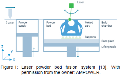
PBF includes processes that use energy-sourced electron or laser beams [10]. In laser powder bed fusion (L-PBF), a powerful high-powered laser melts the required layers of metallic metal powder instead of just sintering it using heat or compression. As the current layer is melted, the previous layers are remelted simultaneously, which allows the current layer to melt into the previous layers during the manufacturing process [11].
Figures 1 and 2 illustrate L-PBF and electron beam powder bed fusion (EB-PBF), respectively, which are often collectively referred to as electron beam melting[12]. Both L-PBF and EB-PBF use the identical powder bed concept, namely, selective layer melting. However, the process setups between these two PBF selective melting processes differ significantly. In the L PBF process illustrated in Figure 1, the laser beam passes through lenses that reflect onto the powder bed platform surface. The laser beam moves the x and y directions during the fabrication path. The bottom layer of powder is melted selectively, and the lifting table (build platform) moves in a downward direction. Thereafter, the recoating arm pushes the second layer of powder from the metal powder supply tank over the previously built surface. The laser scanning process repeats until the fabrication process is completed. To avoid oxidisation of metallic powders during fabrication, the building chamber of the L-PBF is filled with an inert gas.
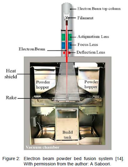
The EB-PBF process illustrated in Figure 2 typically uses a high-powered scanning electron microscope with filament (magnetic coils) that deflects the position of the electron beam to melt the powder selectively. The electron beam is stationed on the top of the powder bed platform, and the lens command the movement of the electron beam. The powder hopper pours powder onto the building platform, the recoater rakes a layer of powder on top of the previous melted layer.
Both the L-PBF and EB-PBF processes require the following steps: machine programming and operation, powder recovery, and post processing [15]. Table 1 compares the mechanical properties, of L-PBF and EB-PBF with traditional wrought based on Ti-6Al-4V, Inconel 718, and Inconel 625. In Table 1 the orientation column illustrates the tensile strength order, with 'horizontal' referring to the direction of deposition layer by layer, and 'vertical' referring to the direction of the completed (accumulation) building process. The table shows that the yield strength and ultimate strength of both the L-PBF and EB-PBF processed parts have values similar to those of the traditional wrought-fabricated parts. However, wrought-fabricated Inconel 625 and EB-PBF processed parts have similar values.
2.2 Direct energy deposition process
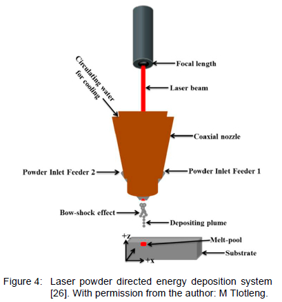
In the DED process, the energy generates a melting pool into the feedstock that has already been deposited. This melting process can use an arc, laser or electron beam as an energy source. The feedstock process either uses laser wire directed energy deposition (LW-DED) as illustrated in figure 3 or laser powder directed energy deposition (LP-DED) as illustrated in Figure 4. The DED machine setup automatically checks the sensors of powder feeder 1 and powder feeder 2, process, the hoppers for EB-PBF and the piston and roller for L-PBF must be filled manually. For PBF, the powder feed-rate of the systems must be checked and confirmed frequently, but in contrast, DED has sensors. Based on system specifications, the baseplate can be orientated in a three axis or a five axis system as they allow or increase the machine's ability to fabricate complex parts or components.
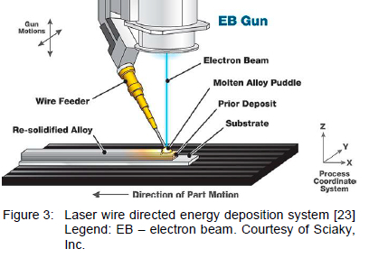
The LW-DED process is illustrated in figure 3. The wire is fed through the feedstock wire feeder and melted by a horizontal electron beam, the wire feeder feeds the wire, and at the same time, the electron beam melts the wire on the building platform. The melted wire solidifies rapidly and forms a similar layer of material. The wire feeder and electron beam move up and back, whereafter the process is repeated for the next layer. The LW-DED process must be performed in a vacuum to prevent air molecules from being deflected by electrons when working with reactive metals. Alternatively, a gas shield can be used to protect the metal wire from contamination.
The LP-DED process is illustrated in Figure 4. The laser beam in the building chamber uses a lens to focus on the building platform, and a powder nozzle simultaneously injects metal powder [24]. The metal powder flows directly on the substrate forming a melting pool after each layer, while the laser source and building platform move simultaneously [25]. The melted powder solidifies rapidly and forms a layer of material as the LW-DED process proceeds. Thereafter, the powder nozzle and laser lens move up, and the process is repeated for the next layer to form a near net shape (very close to the final shape).
The LP-DED building chamber is larger than that used in PBF, which allows vacuum pumping and purge cycles to reduce the oxygen volume [15,16]. This process reduces the flood gas (argon or nitrogen) in the chamber on reactive metals such as titanium parts or components. The DED part is fabricated on the substrate, and post-processing is required to remove the part of substrate, post thermally treatment will improve their properties and even reduce residual stress [15,16]. DED-manufactured parts are mostly near net shapes and typically have a rough finish. The excess powder is vacuumed up after the machine operation. If the powder quality is good, it may be recovered for reuse. However, if the powder has been damaged during the melting process, it is discarded.
Table 2 illustrates the mechanical properties of Ti-6Al-4V, Inconel 718, and Inconel 625 powder-fed, wire-fed, and wrought feedstock. The powder-fed Ti-6Al-4V HIP fabricated part has similar yield strength, ultimate strength, and elongation to the wire-fed Ti 6Al-4V fabricated part, but the vertical elongation of the LW-DED part is greater. The LP DED Inconel 718 fabricated part has a similar yield strength and ultimate strength as the wire-fed Inconel 718 part - both in the horizontal and vertical direction. The elongation of the LP-DED-fabricated Ti 6Al-4V with the as-fabricated condition can be improved with HIP; however, during this post-process, the yield strength increases and the ultimate strength may decrease [25].
2.3 Binder jet printing process
BJP is a powder bed process that uses solidus liquidus phase sintering, which is similar to selective laser melting [31]. BJP consists of a three-step manufacturing process including: distribution of powder, movement of the inkjet nozzle (vertically), and bonding of powder. In the BJP process illustrated in Figure 5, a level roller deposits a layer of metal powder on the lifting before the binding process starts. The inkjet binder nozzles are arranged along the x and y directions to bond the metal powder together. The building platform moves down after bonding process of two layers [25]. The second layer of powder is spread, whereafter the binding repeats after each layer. A powder material is formed and adheres to the binder, which is also known as the green part [13]. There is a substantial difference between the microstructures of BJP and L-PBF manufactured parts [32]. L-PBF parts are characterised by grains from the building direction and dendrites (multi-crystal formation) based on the laser scanning speed, while the BJP process results in faster cooling rates and lower thermal gradients, which lead to more uniformity in all types of grain structure orientation. The mechanical properties of binder metallic parts may vary significantly even though the green bodies are similar [25].
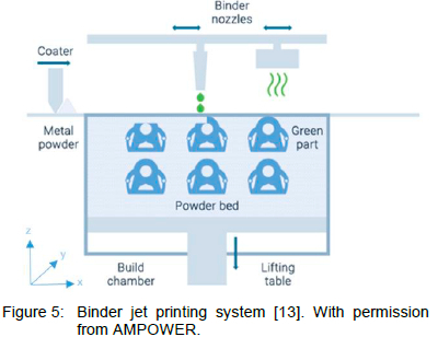
Table 3 illustrates the iron manganese alloy (Fe-Mn), Inconel 625, and stainless steel (316 L) fabricated parts of the BJP and metal injection moulding processes. The relative density varies from 60.7% for Fe-Mn to 99.6% (near fully dense) for Inconel 625. The ultimate strength varies from 228 MPa for BJP to 520 MPa for the metal injection moulding process. The Brinell hardness (HRB) values for BJP and metal injection moulding 361 L are similar; however, as the sintering temperature increase, with mechanical properties (ultimate strength and hardness) decrease for Inconel 625 in terms of Vickers hardness (HV) [33].
2.4 Sheet lamination process
Sheet lamination, also known as ultrasonic additive manufacturing in MAM, is a solid-state technology [37]. It uses ultrasonic vibration under pressure to join similar metal foil materials together by bonding them layer by layer to form as-fabricated parts [38]. The sheet lamination process is illustrated in figure 6. The first metallic sheet is laid on a base plate, and followed by the second sheet, a digitally controlled horn (sonstrode) moves back and forward that provides ultrasonic vibration and pressure. The second metallic sheet is bonded with the previous sheet (first sheet) due to the frequency vibration of the horn. The consolidated region bonds during the process due to frictional heat. Thermal residual stress is avoided by ensuring a short cooling period between each layer. The building layers are removed from the baseplate for post-processing. The basic operating principle of the sheet lamination system has two ultrasonic transducers with a maximum frequency of 20 kHz per transducer that vibrate to a circular disc to create a solid-state weld, as illustrated in figure 6 [39].
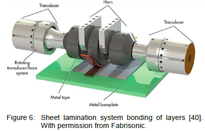
Figure 7 illustrates the process from metal-to-metal contact to attaining a high-strength bond during sheet lamination. The following metals, namely aluminium (Al), stainless steel, copper (Cu) and titanium (Ti), have been bonded with sheet lamination [40]. The sheet lamination manufacturing process has a low temperature, as mentioned, that allows internal geometries to be manufactured. This process is energy efficient and thus cost-effective, and it requires relatively minimal energy to bond different materials as the metal is not melted [40]. The precision of the result depends mostly on the thickness of the layered materials used [41].
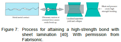
Table 4 illustrates aluminium alloy 3003 (Al3003) fabricated using the traditional wrought manufacturing process and Al6061 fabricated using the sheet lamination process and post-processed parts. Thereafter, the alloys were subjected to tensile testing (yield strength and ultimate strength), which delivered similar results for each process. The mechanical properties show an exceptional change when post ageing thermal treatment was applied [25]. Furthermore, post-heat treatment along with optimised sheet lamination processing parameters enhance the vertical direction properties with no uniform metal layers [25,37].
2.5 Comparison of metal additive manufacturing technologies
Up to this point, this section discussed the general MAM manufacturing processes and the technical aspects thereof. However, the aspects of the MAM processes do differ, and the following differences are discussed in this section: porosity, residual stress, and surface finish. Table 5 compares the features of the L-PBF, EB-PBF, LP-DED, LW-DED, BJP, and sheet lamination processes, whereas table 6 compares the defects thereof.
Although porosity can be reduced in PBF and DED, it is present in BJP. The BJP process should reduce the porous nature of materials with infiltration of consolidation [15]. Both EB PBF and BJP have low residual stress during fabrication processing due to the high operating temperature (effectively in situ stress relief) of these processes with no applied temperature during fabrication processing [11]. The negative effect of operating with high-temperature EB-PBF is that it may alter microstructural characteristics in the material [11]. The surface finish is the best for L-PBF and sheet lamination, but all MAM parts should be near net shapes, as mentioned in the DED process description above. The LW DED deposit rate is faster than L-PBF, EB-PBF and LP-DED since a wire is used during fabrication. sheet lamination, is also much faster than using the powder bed and powder spray methods because the sheet has a remarkable feeding volume at a similar time than the other methods. The heat source principle is the same for all processes, with a higher power input leading to faster deposition rates. Nonetheless, the full melting process requires high power for a faster scan speed to reach a similar energy density. However, if the heat source energy is extremely high, the amount of energy will melt deeper into the substrate, thereby diluting the material with respect to a constant powder mass flow for L-PBF, EB PBF, and LP-DED [44].
3 Conclusion and Further Research Direction
This paper reviewed the MAM processes with the main focus on the manufacturing processes. Each MAM fabrication processes was discussed and compared in terms of features, mechanical properties, feedstock deposition, and common defects. MAM is part of the new industrial revolution associated with industrial material manufacturing and the digital globe. This new form of production is achieved by using layer-by-layer methods for materials until the component or part is fabricated for prototyping and industrial use. MAM fabrication processes with rapid evolution may abandon traditional metal fabrication processes in the near future and become a feasible alternative fabrication root. MAM has evolved exceptionally due to the following advances:
• Reduction of manufacturing time, also known as lead time, which may shorten the development process. Tooling manufacturing can reduce or even eliminate assembly lines [1]. MAM allows for rapid prototyping and proof of concept, and multiple configuration settings can be made for low volume production.
• Reduction of manufacturing and operational cost for PBF, DED and BJP: The high design freedom of additive manufacturing allows fewer subcomponents in complex parts, saving cost and assembly time. Weight reduction and size are important factors in certain industries due to the minimum weight and limited packaging space. The advantage of MAM parts is the reduction in weight, which reduces cost. Laser sintering, a MAM process, can decrease the total weight of components by as much as 50% based on the complexity of the components [45].
• Flexibility of design components: MAM offers excellent complexity of components due to the mentioned reduction of weight and improvement of performance with minimum or no limitations.
• Reduction of the environmental impact of production: The weight reduction of aerospace components reduces fuel consumption and therefore carbon emissions are expected to reduce.
Topics that require further study and investigation include MAM processing parameters, microstructures, and post-processes. The understanding of theoretical studies of some models relating to MAM processes includes building chambers, phase changes, melting pools, heat transfer, mass transfer, residual stress, and atomic diffusion. These models are fundamental for understanding to predict the microstructural and mechanical properties of MAM-fabricated materials.
There are currently new MAM technologies in the research and developing state with the promise of fabricating new materials with superior speed using technologies such as friction deposition, nanoparticle jetting, liquid metal printing, metal slurry deposition, resistance welding, and powder metallurgy jetting [13]. New MAM technologies are announced every year, and these developments will continue for years to come.
References
[1] Engineering Product Design, Additive Manufacturing Process Steps, (2019). URL https://engineeringproductdesign.com/additive-manufacturing-process-steps/.
[2] S. M. Yusuf and N. Gao. Influence of Energy Density on Metallurgy and Properties in Metal Additive Manufacturing. Materials Science and Technology, 33(11):1269-1289, 2017. [ Links ]
[3] A. 52900:2015, Standard Terminology for Additive Manufacturing - General Principles - Terminology, ASTM International, 2015.
[4] C. Qiu, N. J. E. Adkins and M. M. Attallah. Microstructure and Tensile Properties of Selectively Laser-melted and of HIPed Laser-melted Ti-6Al-4V, Materials Science and Engineering: A, 578:230-239, 2013. [ Links ]
[5] N. Hrabe, T. Gnäupel-Herold and T. Quinn. Fatigue properties of a titanium alloy (Ti-6Al-4V) fabricated via electron beam melting (EBM): Effects of internal defects and residual stress. International Journal of Fatigue, 94:202-210, 2017. [ Links ]
[6] ASTM, F2792-12a - Standard Terminology for Additive Manufacturing Technologies, 2013.
[7] C. K. Sudbrack, B. A. Lerch, T. M. Smith, I. E. Locci, D. L. Ellis, A. C. Thompson and B. Richards. Impact of Powder Variability on the Microstructure and Mechanical Behavior of Selective Laser Melted Alloy 718. In Proceeding of the 9th International Symposium on Superalloy 718 and Derivatives: Energy, Aerospace, and Industrial Applications, Springer, New York, pages 89-113, 2018.
[8] A. B. Badiru, V. V. Valencia and D. Liu. From Traditional Manufacturing to Additive Manufacturing. In Proceeding of Additive Manufacturing Handbook: Development for the Defence Industry, CRC Press, New York, pages 3-30, 2017.
[9] D. Deng, R. L. Peng, H. Brodin and J. Moverare, Microstructure and Mechanical Properties of Inconel 718 Produced by Selective Laser Melting: Sample Orientation Dependence and Effects of Post Heat Treatments. Materials Science and Engineering: A, 713:294-306, 2018. [ Links ]
[10] R. Castells. DMLS vs SLM 3D Printing for Metal Manufacturing. Element Materials Technology: London, UK. URL: https://www.element.com/nucleus/2016/06/29/dmls-vs-slm-3d-printing-for-metal-manufacturing, 2016.
[11] W. J. Sames, F. A. List, S. Pannala, R. R. Dehoff and S. S. Babu. The metallurgy and processing science of metal additive manufacturing. International Materials Reviews, 61(5):315-360, 2016. [ Links ]
[12] P. Gradl, D. C. Tinker, A. Park, O. R. Mireles, M. Garcia, R. Wilkerson and C. Mckinney. Robust Metal Additive Manufacturing Process Selection and Development for Aerospace Components. Journal of Materials Engineering and Performance, 31(8): 6013-6044, 2022. [ Links ]
[13] AMPOWER. Laser Beam Powder Bed Fusion. URL: https://additive-manufacturing-report.com/technology/metal/laser-beam-powder-bed-fusion/, 2019.
[14] GE Additive. Electron Beam melting, URL. https://go.additive.ge.com/rs/706-JIU-273/images/GEAdditive_EBM_Whitepaper_FINAL.pdf.
[15] W. J. Sames. Additive Manufacturing of Inconel 718 Using Electron Beam Melting: Processing, Post-Processing & Mechanical Properties. PhD thesis, Texas A&M University, 2015. [ Links ]
[16] T. M. Mower and M. J. Long, Mechanical Behavior of Additive Manufactured, Powder-bed Laser-fused Materials. Materials Science and Engineering: A. 651:198-213, 2016. [ Links ]
[17] Special Metals Corporation. Inconel alloy 718, 1-28. URL: www.specialmetals.com/documents/technical-bulletins/inconel/inconel-alloy-718.pdf, 2007.
[18] Special Metals Corporation. Inconel alloy 625, 1-18. URL: www.specialmetals.com/documents/technical-bulletins/inconel/inconel-alloy-625.pdf, 2013.
[19] EOS. NickelAlloy IN625. URL: www.eos.info/03_system-related-assets/material-related-contents/metal-materials-and-examples/metal-material-datasheet/nickelalloy-inconel/niall-in625-m290_material_data_sheet_06-17_en.pdf, 2010.
[20] E. Petersen-Øverleir. Effect of 3D Printing on the Microstructure and Mechanical Properties of an Inconel 718 Nickel-alloy (UNS N07718). Master's thesis, University of Stavanger, Norway, 2015. [ Links ]
[21] L. Facchini, E. Magalini, P. Robotti and A. Molinari. Microstructure and Mechanical Properties of Ti-6Al-4V Produced by Electron Beam Melting of Pre-alloyed Powders. Rapid Prototyping Journal, 15(3):171-179, 2009. [ Links ]
[22] L. E. Murr, E. Martinez, S. M. Gaytan, D. A. Ramirez, B. I. Machado, P. W. Shindo, J. L. Martinez, F. Medina, J. Wooten, D. Ciscel, U. Ackelid and R. B. Wicker. Microstructural Architecture, Microstructures, and Mechanical Properties for a Nickel-base Superalloy Fabricated by Electron Beam Melting. Metallurgical and Materials Transactions: A, 42:3491-3508, 2011. [ Links ]
[23] INC. Sciacky. Electron Beam Additive Manufacturing. URL www.sciaky.com/additive-manufacturing/wire-vs-powder, 2022.
[24] D. Mahmoud, M. Magolon, J. Boer, M. A. Elbestawi and M. G. Mohammadi. Applications of Machine Learning in Process Monitoring and Controls of L-PBF Additive Manufacturing: A Review. Applied Sciences, 11(24), 11910, 2021. [ Links ]
[25] Y. Zhang, L. Wu, X. Guo, S. Kane, Y. Deng, Y. G. Jung, J. H. Lee and J. Zhang. Additive Manufacturing of Metallic Materials: A Review. Journal of Materials Engineering and Performance, 27:1-13, 2018. [ Links ]
[26] M. Tlotleng. Microstructural Properties of Heat-Treated LENS In Situ Additively Manufactured Titanium Aluminide, Journal of Materials Engineering and Performance, 28:701-708, 2019. [ Links ]
[27] P. E. Ruff. Effect of Manufacturing Processes on Structural Allowables - Phase I. Air Force Wright Aeronautical Laboratories, Technical Report No. AFWAL-TR-85-4128, 1986.
[28] F. Martina, S. W. Williams and P. Colegrove. Improved Microstructure and Increased Mechanical Properties of Additive Manufacture Produced TI-6AL-4V by Interpass Cold Rolling. in: 24th International SFF Symposium - An Additive Manufacturing Conference, pages 490-496, 2013.
[29] P. A. Kobryn and S. L. Semiatin. Mechanical Properties of Laser-deposited Ti-6Al-4V. in: Solid Freeform Fabrication Symposium, 2001.
[30] Optomec. Superalloy Metallurgy Using the LENS Process. URL: www.optomec.com/wp-content/uploads/2014/04/LENS_Superalloy_datasheet_web.pdf, 2014.
[31] K. Small. Characterization of Microstructure and Residual Strain in Inconel 625 Fabricated by Additive Manufacturing. Master's. Thesis, Drexel University, 2007. [ Links ]
[32] W. Frazier. Metal Additive Manufacturing. Journal of Materials Engineering and Performance, 23:1917-1928, 2014. [ Links ]
[33] A. Mostafaei, Y. Behnamian, Y. L. Krimer, E. L. Stevens, J. L. Luo and M. Chmielus. Brief Data Overview of Differently Heat Treated Binder Jet Printed Samples made from Argon Atomized Alloy 625 Powder. Data Brief, 9:556-562, 2016. [ Links ]
[34] D. Hong, D.-T. Chou, O. I. Velikokhatnyi, A. Roy, B. Lee, I. Swink, I. Issaev, H. A. Kuhn and P. N. Kumta. Binder-Jetting 3D Printing and Alloy Development of New Biodegradable Fe-Mn-Ca/Mg Alloys. Acta Biomaterialia, 45:375-386, 2016. [ Links ]
[35] A. Mostafaei, E. L. Stevens, E. T. Hughes, S. D. Biery, C. Hilla and M. Chmielus. Powder Bed Binder Jet Printed Alloy 625: Densification, Microstructure and Mechanical Properties. Materials & Design, 108:126- 135, 2016. [ Links ]
[36] R. Frykholm, Y. Takeda, B. G. Andersson and R. Carlström. Solid State Sintered 3-D Printing Component by using Inkjet (Binder) Method. Journal of the Japan Society of Powder and Powder Metallurgy, 63(7) :421-426, 2016. [ Links ]
[37] P. J. Wolcott, A. Hehr, C. Pawlowski and M. J. Dapino, Process improvements and characterization of ultrasonic additive manufactured structures. Journal of Materials Processing Technology, 233:44-52, 2016. [ Links ]
[38] A. Hehr and M. J. Dapino. Dynamics of Ultrasonic Additive Manufacturing. Ultrasonics, 73:49-66, 2017. [ Links ]
[39] A. K. Gujba and M. Medraj. Power Ultrasonic Additive Manufacturing: Process Parameters, Microstructure, and Mechanical Properties. Advances in Materials Science and Engineering, 1 -17, 2020.
[40] Fabrisonic. 3D Metal Printing without Melting. URL: fabrisonic.com/ultrasonic-additive-manufacturing-overview/, 2019.
[41] Loughborough. Sheet Lamination, URL: www.lboro.ac.uk/research/amrg/about/the7categoriesofadditivemanufacturing/sheetlamination/, 2019.
[42] M. N. Gussev, N. Sridharan, M. Norfolk, K. A. Terrani and S. S. Babu. Effect of Post Weld Heat Treatment on the 6061 Aluminum Alloy Produced by Ultrasonic Additive Manufacturing. Materials Science and Engineering: A, 684:606-616, 2017. [ Links ]
[43] N. Sridharan, M. Gussev, R. Seibert, C. Parish, M. Norfolk, K. Terrani and S. S. Babu. Rationalization of Anisotropic Mechanical Properties of Al-6061 Fabricated using Ultrasonic Additive Manufacturing. Acta Materialia, 117:228-237, 2016. [ Links ]
[44] L. Markusson. Powder Characterization for Additive Manufacturing Processes. Master's thesis, Luleå University of Technology, Sweden, 2017. [ Links ]
[45] B. Blakey-Milner, P. Gradl, G. Snedden, M. Brooks, J. Pitot, E. Lopez, M. Leary, F. Berto and A. Du Plessis. Metal Additive Manufacturing in Aerospace: A Review. Materials & Design, 209:110008, 2021. [ Links ]
Received 15 August 2023
Revised form 4 September 2023
Accepted 29 November 2023

