


Services on Demand
Article
 English (pdf)
 Article in xml format
 Article references
Indicators

Related links
-
 Cited by Google
 -
 Similars in Google
Share

 Permalink
R&D Journal
On-line version ISSN 2309-8988
Print version ISSN 0257-9669
R&D j. (Matieland, Online) vol.37 Stellenbosch, Cape Town 2021
http://dx.doi.org/10.17159/2309-8988/2021/v37a8
ARTICLES
The Structural Design of a High-Performance WBD Brake Disc
A. ChenI; K-J. KangII; F. KienhöferIII
ISchool of Mechanical, Industrial and Aeronautical Engineering, University of the Witwatersrand, Johannesburg, South Africa. E-mail: alanchen.sa@gmail.com
IISchool of Mechanical Engineering, Chon-nam National University, South Korea. Email: kjkang@chonnam.ac.kr
IIISAIMechE member, School of Mechanical, Industrial and Aeronautical Engineering, University of the Witwatersrand, Johannesburg, South Africa. E-mail: frank.kienhofer@wits.ac.za
ABSTRACT
A high performance, newly-developed wire-woven bulk diamond (WBD) ventilated brake disc is introduced to reduce the operating temperatures and mass of conventional brake discs. The use of the highly porous material requires a deeper understanding of the mechanical stresses developed within a brake disc to be developed to improve the disc core strength to withstand the high stresses developed during braking. In this study, experimentally determined solid brake disc stress distribution results, separated into the compressive stresses due to the pad clamping force and the shear stresses due to the applied brake torque, were applied to the reinforcement ofthe WBD core brake disc. The analysis was based on the maximum predicted deceleration conditions of a medium sized truck (Mercedes-Benz Atego). While the WBD core material possessed sufficient strength to withstand the shearing due to the braking torque, the pad clamping load was predicted to cause disc failure. Consequently, straight radial ribs were designed to reinforce the ventilated core, with final rib dimensions of 74x14x2.5 mm, manufactured from mild steel (SAE1006). A total of 10 ribs at 36° intervals were added to reinforce the core, increasing the mass by 0.20 kg compared to the original disc. The newly reinforced WBD brake disc remains lighter than a commercially available pin-finned disc, and is expected to maintain superior thermal performance while possessing the required mechanical strength.
Additional keywords: Ventilated disc, mechanical stresses, braking, stress distribution
Nomenclature Roman
A Area [m2]
c Strut length [m]
d Diameter [m]
E Young's modulus [GPa]
F Force [N]
G Shear modulus [GPa]
p Helical pitch [m]
r Radius [m]
t Thickness [m]
Greek
γ shear strain [dimensionless]
δ displacement [m]
ε strain [m/m]
μ coefficient of friction [dimensionless]
ν Poisson's ratio [dimensionless]
σ normal stress [MPa]
τ shear stress [MPa]
1 Introduction
Vehicle advancement requires components to be lightweight. Reducing vehicle weight improves the fuel economy of internal combustion vehicles, reduces their CO2 emissions, and is a practical way to reduce logistic costs [1-3]. In the case of electric vehicles there is an increased interest in lightweight-ing to increase their driving range [4]. Road handling is improved as a lightweight brake disc reduces the unsprung mass which enhances suspension and deceleration performance [5]. Manufacturers continuously strive to develop better braking systems to increase road safety and reduce accidents. The brake disc cannot be made lighter without ensuring the disc possesses adequate thermal capacity to absorb heat [6-8]. High temperatures are developed by the brake disc (rotor) due to the frictional sliding contact with the pads during braking. Excessive temperatures deteriorate the brake performance and may ultimately result in failure [7]. During braking a portion of the heat is absorbed by the thermal capacity or mass of the disc while the remainder is primarily dissipated by convection [9]. Therefore, the mass of a brake disc cannot be reduced unless the heat dissipation characteristics of the disc are improved.
The highly porous cellular wire-woven bulk diamond (WBD) has been shown to be an excellent medium for the ventilated core of a brake disc [10-13] to improve the heat dissipation characteristics of a brake disc as the convective cooling is enhanced. Laboratory tests [10, 12] showed the prototype WBD disc to operate at a 15-25% lower steady state temperature as compared to the commercially available pin-finned disc or solid brake disc. The results were confirmed with on-the-vehicle tests [13].
Mew et al. [10] selected the WBD material as the highly porous medium in the ventilated channel of the brake disc because of its superior strength over other types of cellular structures. The yielding mechanism of the WBD material is complicated and highly dependent on the wire diameter and slenderness ratio of the struts. The equivalent compressive strength of the material is in the region of 6 MPa [14]. The material has good strength especially when normalised by its mass, but is significantly weaker than grey cast iron or mild steel.
A brake disc is subjected to both thermal and mechanical loads. Initial laboratory strength tests of the WBD brake disc showed that the disc was able to withstand a pneumatic chamber braking pressure of 4 bar but failed at a braking pressure of 5.2 bar [15]. The upper limit of braking pressure in service is approximately 7 bar [16, 17].
During braking, the porous ventilated WBD brake disc core must possess the disc strength to resist failure due to both the compressive clamping and frictional shearing loads at the upper limit of the applied braking pressure. In this study the loading mechanism of a solid brake disc is analysed. The experimental stress distribution results are applied to the structural reinforcement of the WBD brake disc.
2 Wire-woven Bulk Diamond
2.1 Overview
Ventilated brake discs are used in heavy vehicles due to their ability to dissipate heat more effectively [18]. However, the current brake disc topology is limited by the casting process [19] which inhibits the use of a multitude of thin pin fins in the ventilated channel as thin cross sections cannot be economically cast without defects. Thick cross sections adversely affect the convective heat transfer performance of the brake disc [11]. This led to the introduction of a cellular metal material into the ventilated core of a patented WBD brake disc by Mewetal. [10].
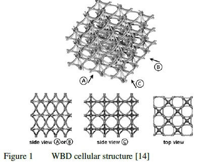
Wire-woven metals are composed of periodic topologies with open cells similar to truss type periodic cellular metals (PCMs). Honeycomb and corrugated metals are typical examples of the PCM structure. Wire-woven metals primarily serve as a low density core of sandwich panels; where the core can provide additional functions to the load bearing capability. The cores are utilised for heat transfer [20], catalyst support [21], reinforcement of matrices [22], and seismic dampers [23]. Strucwire, a wire-woven material similar to WBD, can be integrated into a car buffer bar as an impact buffer [24, 25]. The cellular metal structure has good strength and rigidity as the wires have high strength and stiffness. The wire-woven bulk diamond cellular structure is composed of regular octahedrons and cuboctahedrons as shown in figure 1. The "diamond" truss nomenclature arises from the side view of the structure which reveals a diamond shape [14].
2.2 Axial Strength and Stiffness
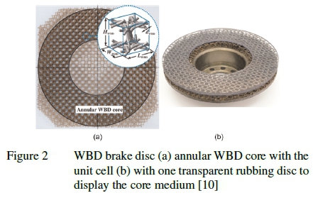
The WBD core of the brake disc is manufactured using cold-rolled mild steel wires (SAE1006B) with diameters of d = 1.5 mm and a helical pitch of p = 19.0 mm. The WBD unit cell (see figure 2) dimensions are: length = 9.5 mm, width = 9.5 mm, height = 14.0 mm. The porosity of the WBD core is approximately 0.9 and the surface area density is approximately 255 m2/m3 [10, 11], calculated based on the idealised diamond unit cell with straight struts. The curvature of the struts of the helical ligaments would increase the relative density and surface area density by approximately 15% [11].
For the above dimensions, the measured equivalent yield strength, maximum strength, and Young's modulus of the WBD core are 3.2 MPa, 4.8 MPa, and 1.08 GPa, respectively [10, 11].
2.3 Shear Strength and Stiffness
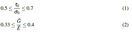
The curved struts of the wire-woven metals degrade the mechanical properties, such as the strength and stiffness, of the wire-woven structures [26]. Therefore, the strengths of the wire-woven materials with the more curved struts are more likely to be "bending-dominated" than "stretching-dominated" [27]. As a first estimation, the shear strength of the WBD porous material can be determined from the compressive strength using an expression of the strength ratios obtained from the analytic solutions [28]. For a specified relative density, the ratio of the equivalent shear strength to the equivalent compressive strength is shown in equation 1. Similarly, the equivalent shear modulus of the multi-layered metal can be estimated from the equivalent Young's modulus, as shown in equation 2 [25].
3 Experimental Details
3.1 Test Sample
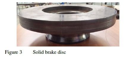
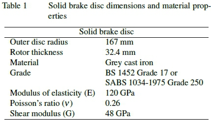
Testing was conducted on a commercially available solid brake disc (see figure 3). The grey cast iron disc was cast as a single unit and heat treated, and sized to fit the hub of a Mercedes-Benz Atego 500 (medium-duty truck). A uniform thickness was obtained around the solid brake disc by skimming the disc prior to testing. The solid brake disc dimensions and material properties are shown in table 1.
3.2 Brake Test Rig Facility
A custom-built brake test rig replicated the applied braking loads experienced by the brake disc of a medium-duty truck, as shown in figure 4. The test rig consists of a 37 kW AC induction motor geared to a reduction gearbox that transmits the torque to the shaft through a flexible coupling. The shaft manufactured from EN8 mild steel has an outer diameter of 60 mm, and rotates on two bearings, and is flanged into a hub on the opposite end to allow the mounting of the brake disc. The motor speed and/or torque is regulated by the frequency inverter.
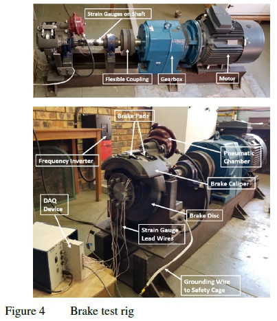
A pneumatic floating brake caliper with a single piston applies the brake pressure on the brake disc through the brake pads. The caliper is actuated with a pneumatic chamber controlled through a digital proportional pressure regulator. Externally supplied compressed air at 6 bar is fed to the inlet of the pressure regulator, thus the braking force is regulated through controlling the air pressure supplied to the pneumatic chamber. The set point is selected on the pressure regulator.
Biaxial strain rosettes installed on the shaft measured the strains to calculate the applied brake torque. Multiple uniaxial strain gauges were installed on the brake disc to measure the disc strains. The strain gauge signals were recorded and conditioned using a data acquisition (DAQ) system and LabVIEW.
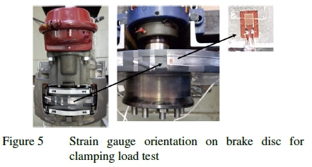
The first test performed was the clamping load test to characterise the compressive stresses experienced in the brake disc due to the pad clamping load under the braking action, with the test performed under the condition of a stationary brake disc. The strain gauges were aligned in the direction of the applied clamping force to measure the strains in the disc core due to the compressive braking load (figure 5).
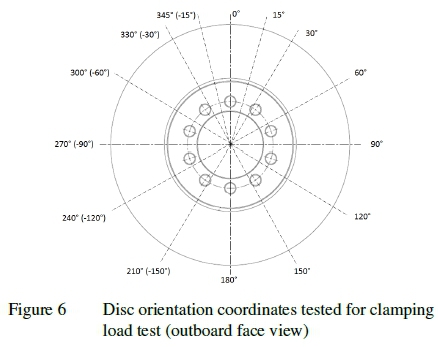
The disc orientation coordinates shown in figure 6 are used to present the measured strain readings at the different positions on the disc core. Positive angles are designated as clockwise rotation around the disc. For each position, the pneumatic chamber was pressurised, which applied the pad clamping load on the disc, and the strain gauge measurements were recorded. The chamber was then depressurised releasing the clamping load. The test was completed at four different pneumatic chamber pressures: at 1 bar, 2 bar, 4 bar, and 6 bar; for all the disc orientation coordinates. These pressures were equivalent to the pad clamping forces of 11 kN, 24.6 kN, 50.4 kN, and 77.4 kN, respectively.
3.3.2 Applied Torque Load Test
The second test performed was the applied brake torque load test to characterise the disc shear stresses due to the applied brake torque. The shaft torque (hence disc braking torque) was determined using two pairs of biaxial 0°/90°stacked strain rosettes installed on the shaft.
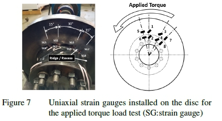
It would be ideal to measure the strains on the contacting surface of the disc/pad interface. However, installing strain gauges at the contact interface region would crush them. Thus, the uniaxial strain gauges were installed on the brake disc face directly below the outboard pad contact interface to measure the strains as close to the contact interface without damaging the equipment.
Eight uniaxial strain gauges were installed on the disc outboard face to measure the strains due to the applied brake torque, as shown in figure 7, labelled strain gauge 1 to strain gauge 8. The uniaxial strain gauges were installed at two different radii on the disc: one upper location and one lower location. Each pair of strain gauges (upper and lower location) were positioned on a radial line indicated by the white lines in figure 7. Ideally, strain rosettes would have been installed in a single location on one radial line. However, to prevent damage to the measuring equipment, the installation of the strain gauges were confined to the narrow region between the disc hub and directly below the brake pads. Thus, it was required to install the uniaxial strain gauges on different radial lines. By rotating the disc, the normal strains in the direction of 0°, 45°, and 90° to the radial direction could be measured at the same point. Two pairs of strain gauges (strain gauge 1 and 2, and strain gauge 3 and 4) were used to measure the normal strains in the 45° orientation on the disc to evaluate repeatability.
Referring to figure 6, the torque load test was completed at all the disc coordinates for the clamping load test, with the additional positions of 45°, 75°, 285° (or -75°), and 315° (or -45°). To prevent damage to the data acquisition equipment, a pneumatic chamber pressure of 4 bar (equivalent to 50.4 kN of pad clamping force) was applied to the brake disc to ensure it would not rotate under the maximum applied torque (approximately 1030 Nm). The torque was applied in a counterclockwise direction as viewed from the outboard standpoint,
and the disc face strains were measured at all the disc orientations. The strain gauge measurements were converted into stress components. The shear stress, τrθ, was calculated using the shear strain, yrg, and the shear modulus (G) by applying Hooke's law. (r: along the radial direction of the brake disc; θ: along the circumferential direction of the brake disc).
4 Experimental Clamping Load Test
The longitudinal stress (σz) in the solid brake disc with respect to disc orientation due to the applied clamping loads of 1, 2, 4, and 6 bar pneumatic chamber pressures (equivalent to applied pad compressive forces of 11.0 kN, 24.6 kN, 50.4 kN, and 77.4 kN, respectively) are shown in figure 8.
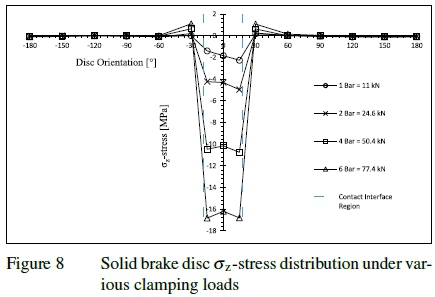
The vertical 0° disc radial line coincides with the centreline of the disc/pad contact interface. Referring to figure 8, the stress distributions are symmetric about the 0° vertical centreline (accounting for experimental error), which shows a near uniform and equal distribution of the stresses on either side of the centreline.
The pad was inserted into position in the brake caliper with the top arc length of the pad friction material flush with the top circumferential segment of the disc, which formed the upper border of the contact interface region. The ratio of the pad arc length to the disc circumference was 10.1%, which converts to a subtended angle of 36.4° on the disc. The angle is indicated as the region between the two vertical dashed lines labelled "Contact Interface Region" in figure 8; with 18.2° split on each side of the 0° vertical centreline. The stress data points greater than 1 MPa in magnitude are all within the designated "Contact Interface Region". The highest compressive stresses measured in the brake disc are concentrated within the disc/pad contact interface region, where the stresses are constant in this region as there are small differences between the stress magnitudes between the discrete data points of-15°, 0°, and 15°. The magnitude of the compressive stress decreases rapidly when traversing from -15° to -30° and similarly from 15° to 30°.
The stresses experienced by the solid brake disc due to the compressive clamping load applied by the brake pads are limited to the disc/pad contact interface only and do not distribute to the other regions of the disc, as zero stresses where measured in the regions away from the disc/pad contact interface between -60° to -180° and 60° to 180°.
5 Experimental Applied Torque Load Test
An applied brake torque load of 1005 Nm was applied in a counterclockwise direction as viewed from the outboard side of the disc. The measured shear stresses, τrθ, on the disc outboard face just underneath the brake pad at the upper location (r = 96 mm) and the lower location (r = 88 mm) due to the applied brake torque load are shown in figure 9. Since the convention of the disc orientation positions were selected as clockwise positive, the leading edge is indicated by the positive angle orientations (i.e. the region located on the right of the 0° axis of the stress results) and the trailing edge is indicated by the negative angle orientations (i.e. the region located on the left of the 0° axis). The disc/pad contact interface exists between the region of -18.2° to 18.2° labelled as the "Contact Interface Region" in the stress results (figure 9).
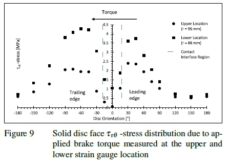
The shear stresses at the upper location occur around the entire disc, in contrast to the clamping load stresses (figure 8) which are localised at the disc/pad contact interface. The shear stresses increase abruptly within the vicinity of the disc/pad contact interface with a steep and sudden change of gradient. The stresses flatten moving away from the contact interface, to stress values of between 0.5 MPa and 0.6 MPa in the far regions on the opposite end of the disc. The concentration of the shear stresses in the region of the disc/pad contact interface is to be expected since the frictional forces that develop the brake torque are localised in this region.
In contrast to the clamping load test normal stress distribution (figure 8) which is symmetric to within measurement uncertainty, the applied torque load shear stress distribution is asymmetric. The shear stress measured at the upper location (denoted by circles in figure 9) is significantly higher on the leading edge as compared to the trailing edge; the shear stress at 15° (leading edge) is 1.05 MPa as compared to the shear stress at -15° (trailing edge) of 0.30 MPa, thus 250% greater. The increased stress at the leading edge as compared with the trailing edge is further observed in the regions adjacent to the contact interface; the shear stress at 30° is 2.4 MPa as compared to the shear stress at -30° of 0.88 MPa, thus the stress at the leading edge is 172% greater than the trailing edge. The phenomenon of increased stress at the leading edge as compared to the trailing edge is also observed in the shear stresses measured at the lower location (denoted by squares in figure 9) but this is less pronounced. At the lower location the shear stress at 15° (leading edge) is 22% greater as compared to the shear stress at -15° (trailing edge). Similarly, for the region adjacent to the contact interface; the shear stress at 30° is 17% greater as compared to the shear stress at -30°. A significant difference is that the magnitude of all the shear stresses at the lower location are greater than the measurements from the upper location strain gauges at the corresponding orientations. The greater shear stress at the lower location is due to the applied brake torque being transferred from the disc circumference to the centre of the disc. Since the area decreases (with decreasing radius), the shear stress increases. Additionally, the lower location strain gauges are in close proximity to a disc recess and accompanying stress concentration effect.
On either side of the disc/pad contact interface region, the shear stresses reached similar values; at the upper location (denoted by circles) the shear stress at 45° (leading edge) is 2.36 MPa as compared to the shear stress at -45° (trailing edge) of 1.94 MPa, thus 21% greater. In contrast at the lower location (denoted by squares) the shear stress at 45° (leading edge) is 3.74 MPa as compared with the shear stress at -45° (trailing edge) of 4.22 MPa, thus 11% less. The shear stresses interestingly decrease at an orientation much further away from the disc/pad interface region on the trailing edge side as compared to the leading edge side; the steepest gradient of decrease is at -120° on the trailing edge side as compared with 75° on the leading edge side. While no convincing argument is advanced for the cause of these asymmetries, the asymmetry is in agreement with the finite element analysis results of Abu Bakar et al. [29]. Their measurements of the disc/pad contact pressures when a brake rotates were also asymmetric; higher on the leading edge of the contact interface compared with the trailing edge. Their results show that the leading edge between the pad and disc maintains contact but the trailing edge loses contact [30].
The shear stress at the geometric centre of the disc/pad contact interface (0° coordinate) is near zero and the magnitudes of the stresses in the immediate region of the contact interface of -15° and 15° are lower than the adjacent regions of non-contact at -30° and 30°, respectively. The clamping load of the brake pad and consequent friction restrains deformations and strain formation under the disc/pad contact interface. The constrained deformations explain the cause of the lower magnitude of shear stresses underneath the brake pad as compared to those in the region away from the contact interface. The test procedure for this study did not allow sliding between the disc and pad interface, however, sliding would occur during in situ braking, likely allowing for greater shear stress formation in the contact interface.
6 Reinforcement of the WBD Brake Disc
6.1 WBD Prototype Brake Disc
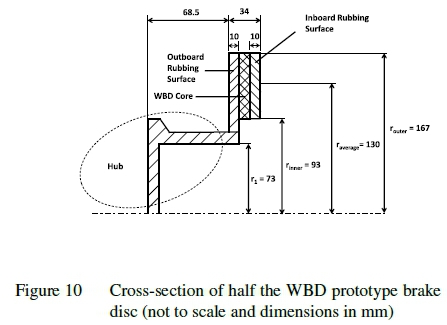
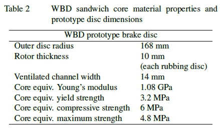
The sandwich core of the WBD brake disc is shown in figure 2 and the cross-section of the WBD brake disc with key dimensions is shown in figure 10. The WBD core is sandwiched between the two solid rubbing surfaces. The disc dimensions and equivalent material properties of the WBD prototype brake disc are shown in table 2. The dimensions of the WBD brake disc are similar to the solid brake disc as both discs are to be fitted on the same vehicle, the Mercedes-Benz Atego.
6.2 Stress Prediction of the WBD Prototype Brake Disc
The experimental solid brake disc stress distribution results (refer to Section 4 and Section 5) are applied to the WBD brake disc to determine the required reinforcement to the WBD core to ensure adequate strength of the core material for an improved lightweight brake disc.
6.2.1 Disc Stress Developed Under Applied Brake Torque Load
Assuming the condition of applying the brakes on a vehicle where the maximum torque developed is 6841 Nm. Half of the total torque from the brake pads to the shaft is transmitted through each disc face (since the frictional force between the pad and disc is generated on both sides of the disc), i.e. the torque developed on the inboard side of the disc is 3421 Nm. The inboard side is analysed as the torque load is transmitted through the core material to the disc hub.
Applying the distribution of the shear stresses from the solid brake disc test results (refer to Section 5): it is assumed that the shear stresses experienced by the WBD disc when loaded with the applied brake torque are distributed around the entire disc. As a first order approximation, the annu-lus area between the outer radius (167 mm) and inner radius (93 mm) of the rubbing surface of the disc (see figure 10) is the area upon which the shear stress acts, presenting a non-conservative approach. Since the shear stresses are distributed around the entire disc, it is approximated that the torque is the result of an average force that acts on the disc annulus area at the radial distance (raverage) measured from the centre of the disc to the centre point of the annulus area, raverage= 130 mm. The average force is 26.3 kN acting in the direction of the frictional force between the disc and pad interface. The average shear stress is calculated as the average force acting over the annulus area of the rubbing surface (60.4 χ 10-3 m2) which equals to 0.44 MPa, acting around the entire disc circumference. Referring to the shear stress results at the upper location for the solid disc in figure 9, the maximum shear stress was 2.40 MPa; while the shear stress at the far regions away from the contact interface was 0.59 MPa. The ratio of the maximum shear stress to the shear stresses distributed at the far region is 4.05. As an approximation to account for the localised deformation effects at the WBD disc/pad contact interface, the ratio represents a stress concentration factor (SCF = 4.05) that is applied to the average shear stress to predict the WBD maximum shear stress, which is 1.76 MPa.
The maximum shear stress is compared with the WBD material properties to ensure adequate strength. The equivalent compressive strength of the WBD material is approximately 6 MPa [14]. Referring to the Shear Strength and Stiffness (Section 2.3), the shear strength as a first order approximation can be determined from the analytic solution (equation 2) that presents a simplified strength ratio. The shear strength divided by the compressive strength of the WBD material is approximately between 0.5 to 0.7; the equivalent shear strength of the WBD core is thus between 3 MPa to 4.2 MPa. Analytical solutions and numerical simulations performed by Song et al. [31] determined that the shear strength (defined as the strength at a strain of 5% in the study) to be between 2.4 MPa to 2.7 MPa; albeit the specimens analysed were for a slenderness ratio that was 7.5% less than that for the WBD core for the brake disc. Analysing the results from Song et al. [31] it is expected that the shear strength to be greater for the larger slenderness ratio. Additionally, the WBD material specimen tested by Song et al. [31] was manufactured from SUS 304 stainless steel; while the WBD brake disc core is fabricated using cold-rolled mild steel SAE1006B wires. The yield strength of cold-rolled mild steel wires is greater than stainless steel wires. Nonetheless, the approximated maximum shear stress for the WBD disc (1.76 MPa) is expected to be less than the shear strength of the WBD core material. Therefore, it is not required to reinforce the shear strength component of the WBD brake disc. The discussion and analysis that follows focuses on the com-pressive loading of the clamping force.
6.2.2 Disc Stress Developed Under Pad Clamping Load
Referring to the solid brake disc clamping load test results in Section 4, it was shown that the compressive stresses due to the clamping load were concentrated at the disc/pad contact interface and negligible elsewhere. As a first order approximation, the compressive stresses due to the pad clamping force can be determined by dividing the force by the pad area and applying a stress concentration factor (SCF). Referring to figure 8 the maximum compressive stress experienced by the solid brake disc was 16.8 MPa when loaded with a pad clamping force of 77.4 kN (or 6 bar pneumatic chamber pressure). The brake pad area was 8.5χ 10-3 m2. Thus, for a pad compressive force of 77.4 kN, the average compressive disc stress equals 9.11 MPa. The ratio of the maximum compres-sive stress to the average compressive stress is 1.85, which is the stress concentration factor to be applied in the estimation of the WBD disc compressive stresses. The application of the solid disc stress distribution provides insight into the WBD behaviour such that an estimation is possible.
According to the European Council Directive (EEC 71/320) [16] the pressure in the feed pipe to the brakes must be 6.5 bar. The United States of America Federal Motor Vehicle Safety Standards (FMVSS 121) [17] require brake systems capable of increasing the air supply to 100 psi (6.9 bar). Therefore, the WBD core will be designed to withstand a maximum pneumatic chamber pressure of 7.0 bar, equivalent to the clamping force of approximately 90.7 kN.
6.3 Reinforcement Design of the WBD Prototype Brake Disc
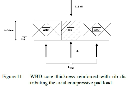
For a relatively conservative approach a safety factor of 1.3 is applied to the force (90.7 kN), thus the new force required in the design of the core reinforcement is 118 kN. The WBD brake disc is proposed to be strengthened through reinforcing the WBD core with solid material providing the necessary strength. The reinforcement design is required to be cost-effective and practical to implement. The addition of ribs (or vanes) to the core is practical as vaned brake discs are well established. The amalgamation of the WBD material and the supporting ribs into the brake disc core creates a hybrid core that possesses improved thermal dissipation characteristics together with the required strength properties. Straight radial ribs are used to reinforce the core to allow for cooling flow through the ventilated channel. Applying the solid brake disc stress distribution results; it is assumed that the compressive stresses are concentrated at the disc/pad contact interface only, thus the contact interface is the region considered for the reinforcement i.e. the pad area.
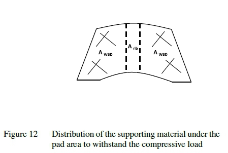
The WBD ventilated core thickness (sandwiched between the two rubbing surfaces in figure 10) is 14 mm. The reinforcing ribs are thus required to be 14 mm in height. Figure 11 shows the WBD disc core reinforced with the solid rib material sandwiched between the WBD material. The compres-sive pad force is transferred through the rubbing surface to the core. Referring to figure 11 and figure 12, the compressive pad force of 118 kN is supported by both the WBD and rib material, generating the FWBD and Frib internal forces respectively. Since the stresses are assumed to be concentrated in the disc/pad contact interface, only the pad area is considered for the reinforcement.
Considering the free body diagram of the core, the vertical force equilibrium is given by equation 3:

The problem is statically indeterminate and requires consideration of the compatibility conditions. The application of the compressive load onto the rubbing surface causes equal deformation of both the solid rib and WBD material in the core. This results in the deformation (δ) relation in equation 4.

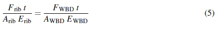
Applying the load-displacement relationships result in equation 5. The equivalent Young's modulus of the WBD porous material is 1.08 GPa. The solid ribs are manufactured with the same mild steel material (SAE1006) as the two solid rubbing surfaces that sandwiches the disc core, which has a Young's modulus of 200 GPa.
Where:
F: Internal force [N]
t: Original core thickness [m]
A: Cross-sectional area [m2]
E: Modulus of elasticity (Young's modulus) [Pa]
The equivalent compressive strength of the WBD material is 6 MPa. Referring to Section 6.2.2 the stress concentration factor (SCF) of 1.85 is applied to account for the ratio between the maximum compressive stress and the average compressive stress. Therefore, the SCF is applied to the WBD average normal stress (σWBD) as shown in equation 6.

The pad area (Apad) is 8.5 χ 10-3m2. Referring to figure 12, the pad area is segmented into two areas; namely the area wherein the WBD material supports the load (AWBD) and the area wherein the rib supports the remaining load (Arib). The relationship between the two areas is expressed with equation 7.

Solving equation 3 and equation 5 simultaneously, and rearranging the terms in equation 6 and equation 7 results in the expression for Arib, as shown in equation 8.
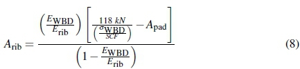
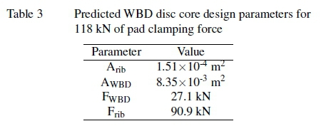
Substituting the numerical values into equation 8 results in Arib equal to 1.51x10⁻⁴m2. The other parameters are subsequently calculated, with the results shown in table 3. Therefore, the design of the reinforcing rib is based on the calculated Arib value. For the design analysis, it is based on the instantaneous point of the disc rotation where the reinforcing rib coincides with the centre position of the pad area as shown in figure 12, where the rib is approximated as a rectangular geometry. The vertical length at the centre of the pad is 66 mm, which will also be the length of the rib. The rib area and length are known, thus the width of the rib is 2.29 mm. Therefore, the minimum required width for the rib to withstand the clamping pad force of 118 kN is 2.29 mm. To reduce costs, dimensions should be specified to those readily available, hence the reinforcing ribs are designed to be mild steel flat bars 14 mm χ 2.5 mm. The WBD core is brazed onto the two mild steel rubbing surfaces. Since the reinforcing ribs are to be fabricated using the same mild steel grade as the latter, the identical brazing method is utilised where the ribs are brazed simultaneously with the WBD material onto the rubbing surfaces. The in-depth fabrication process of the WBD structure and the insertion into the brake disc is discussed by Mew et al. [10] and Kang [25].
It is required that at any given moment in time of the disc rotation that there is a minimum of one rib providing support in the disc core under the contact interface (refer to figure 13). The reinforcement of the disc core with the straight ribs will unavoidably increase the overall mass of the disc. However, there is merit in reinforcing the WBD brake disc as it possesses superior heat dissipation properties as compared to the commercial brake discs. Consequently, one of the criteria of the reinforcement design is to utilise the minimum number of ribs to achieve the required strength to avoid significantly increasing the overall mass of the disc. Therefore, the core should be reinforced with a sufficient number of ribs to withstand the maximum exerted pad clamping force, whilst not significantly increasing the overall weight. Referring to figure 13 of the pad in contact with the disc, the subtended angle that encompass the two lower edges of the pad is θ = 78.2°. Therefore, the angle of the pad centre line to either bottom edges of the pad encompass an angle of 39.1°. Considering the scenario that a rib is located at the 0° position (centre of pad), if a second rib is approaching the leading edge (hence aligned on the bottom right edge of the pad 39.1° away from the pad centre line) where it is on the boundary of the contact interface and therefore is not supporting the load yet. With a slight disc rotation, the rib in the centre position rotates counterclockwise; the second rib originally positioned on the edge of the contact interface begins to support a portion of the load. The incoming second rib will gradually support more of the load as it rotates. When the second rib reaches the centre position of the pad, the first rib will be exiting the contact interface on the trailing edge on the bottom left edge of the pad. The second rib becomes the sole rib within the interface supporting the load. However, concurrently, a third rib will be entering the contact interface on the leading edge from the bottom right pad edge, and the rotation motion will repeat with the ribs exiting and entering the interface. Therefore, if the ribs are spaced in intervals of at least 39.1° in the disc core, there will be a minimum of one rib within the contact interface at any moment in time during the disc rotation.
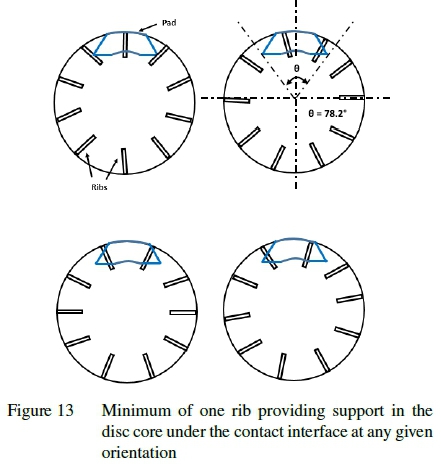
Consequently, the disc core is reinforced with 10 ribs in total, installed in 36° intervals around the core. Referring to figure 10, the core encompass the region between the outer and inner radius of the annulus. Therefore, although the rib is designed to reinforce the pad area only, for practicality during manufacturing the rib will extend from the outer radius to the inner radius of the annulus resulting in the rib length of 74 mm. The final dimensions of the rib are 74x14x2.5 mm. The density of the mild steel (SAE1006) ribs is 7.87 x 10³ kg/m3, therefore the total mass added by the 10 ribs to the original disc is 0.20 kg. The newly designed reinforced WBD brake disc (13.67 kg) remains lighter than the commercial pin-finned disc (14.22 kg).
The introduction of the ribs (vanes) to strengthen the WBD disc core will inexorably affect the heat transfer performance. However, vaned brake discs are well established. The suction side of the vanes are affected by the formation of flow recirculation regions reducing the flow of cooling air in the ventilated channel. However, it is expected to be compensated by the WBD core material that increases the convective heat transfer of the brake disc by inducing stronger flow mixing in the ventilated channel, combined with a greater heat transfer area [11]. Furthermore the thin three-dimensional WBD ligaments result in a more uniform heat transfer reducing thermal stresses. With all these factors considered, it is expected that the novel WBD brake disc is viable after reinforcement.
7 Conclusion
The experimental solid brake disc stress distribution results were applied to the newly developed highly porous WBD brake disc into improving the disc strength. The compressive stresses due to the pad clamping force, and the shear stresses due to the applied brake torque load were analysed and applied to determine the approximate required reinforcement in the WBD core to ensure adequate strength to withstand the high stresses developed during braking.
The WBD core was analysed based on maximum deceleration conditions where the torque acting on each disc face was approximately 3421 Nm. The approximate first order average shear stress was calculated to equal 0.44 MPa acting upon the WBD annulus area. A stress concentration factor (SCF = 4.05) was applied to account for the contact interface local deformation effects, resulting in a predicted maximum shear stress of 1.76 MPa. It is lower than the equivalent shear strength of the WBD core material (between 3.0 MPa and 4.2 MPa). Therefore, based on the predicted shear stresses it was not required to reinforce the WBD core for the expected operating torque range.
The reinforcement of the core was designed to withstand a maximum pneumatic chamber pressure of 7 bar. A safety factor of 1.3 was applied, hence the pad clamping force considered for the reinforcement design was 118 kN. The com-pressive stresses due to the pad clamping load is expected to be concentrated at the disc/pad contact interface only, thus the interface was the area considered for reinforcement. A stress concentration factor (SCF = 1.85) was applied to account for the difference between the maximum compressive stress and the average compressive stress (calculated over the pad area). The reinforcement was designed so that at any given point in time of the disc rotation, there was a minimum of one rib providing support in the core under the contact interface area. The ribs are designed to be brazed between the WBD material in the core. The minimum required rib width to withstand the maximum pad clamping force is 2.29 mm. Rounding up the final dimensions of the designed rib are 74 x 14x2.5 mm. The core is reinforced with 10 solid mild steel (SAE1006) ribs in total, installed at 36° intervals around the core. The total mass added by the 10 ribs is 0.20 kg, thus the newly reinforced WBD brake disc remains lighter than the commercially available pin-finned disc.
Acknowledgements
The authors would like to thank the Manufacturing, Engineering and Related Sector Education and Training Authority (merSETA) for financial support.
References
[1] S. Mohapatra and S. Das. Introduction of high strength steel for commercial vehicles-light weighting of vehicles. SAE Technical Paper, (2014-28-0002), 2014.
[2] O. A. Olatunbosun, A. Gauchia, M. J. L. Boada, and V. Diaz. Dynamic performance analysis of a light van body-in-white structure. Proceedings of the Institution of Mechanical Engineers, Part D: Journal of Automobile Engineering, 225(2):167-177, 2011. [ Links ]
[3] W. J. Joost and P. E. Krajewski. Towards magnesium alloys for high-volume automotive applications. Scripta Materialia, 128:107-112, 2017. [ Links ]
[4] J. T. J. Burd, E. A. Moore, H. Ezzat, R. Kirchain, and R. Roth. Improvements in electric vehicle battery technology influence vehicle lightweighting and material substitution decisions. Applied Energy, 283:116269, 2021. [ Links ]
[5] D. Hrovat. Influence of unsprung weight on vehicle ride quality. Journal of Sound and Vibration, 124(3):497-516, 1988. [ Links ]
[6] R. Limpert. Brake design and safety. SAE, 3rd edition, 2011.
[7] A. J. Day. Braking of road vehicles. ButterworthHeinemann, 2014.
[8] T. Mew, T. Kim, K-J. Kang, and F. W. Kienhöfer. Thermal comparison of solid and ventilated brake disc rotors. In Proceedings: 9th South African Conference on Computational and Applied Mechanics, Somerset West, South Africa, 2014.
[9] A. Adamowicz and P. Grzes. Influence of convective cooling on a disc brake temperature distribution during repetitive braking. Applied thermal engineering, 31(14-15):2177-2185,2011. [ Links ]
[10] T. D. Mew, K-J. Kang, F. W. Kienhöfer, and T. Kim. Transient thermal response of a highly porous ventilated brake disc. Proceedings ofthe Institution ofMechanical Engineers, Part D: Journal ofAutomobile Engineering, 229(6):674-683, 2015. [ Links ]
[11] H. B. Yan, T. Mew, M-G. Lee, K-J. Kang, T. J. Lu, F. W. Kienhöfer, and T. Kim. Thermofluidic characteristics of a porous ventilated brake disk. Journal ofHeat Transfer, 137(2), 2015. [ Links ]
[12] F. W. Kienhöfer, S. Zedi, T. Kim, and K. J. Kang. Characterising the thermal performance of a novel lightweight brake disc with wire-woven ventilated channel at varying speeds, 2016.
[13] M. Atkins, B. Muhammad, A. Suhail, F. W. Kienhöfer, K. J. Kang, and T. Kim. Field testing of a highly porous ventilated brake disc, 2017.
[14] M-G. Lee, G-D. Ko, J. Song, and K-J. Kang. Compres-sive characteristics of a wire-woven cellular metal. Materials Science and Engineering: A, 539:185-193, 2012. [ Links ]
[15] A. Chen. Mechanical testing of a WBD disc, 2016.
[16] Official Journal of the European Union. Council directive 71/320/EEC on the approximation of the laws of the member states relating to the braking devices of certain categories of motor vehicles and their trailers. Concil directive, The Council of the European Communities, 1971.
[17] Federal motor vehicle safety standards number 121, air brake systems: Chapter V part 571 subpart B. Technical report, National Highway Traffic Safety Administration (Department of Transportation), 2009.
[18] T. Gilles. Automotive chassis: brakes, suspension, and steering. Delmar Learning, 2005.
[19] J. Campbell. Castings. Butterworth-Heinemann, 1991.
[20] J. Tian, T. J. Lu, H. P. Hodson, D. T. Queheillalt, and H. N. G. Wadley. Cross flow heat exchange of textile cellular metal core sandwich panels. International journal ofheat and mass transfer, 50(13-14):2521-2536, 2007. [ Links ]
[21] B-C. Choi, J-W. Jeong, J-H. Joo, and K-J. Kang. A feasibility study of wire-woven cellular metal as catalytic support material. Advanced Engineering Materials, 11 (7):536-540, 2009. [ Links ]
[22] C. Sennewald, S. Kaina, D. Weck, A. Gruhl, M. Thieme, G. Hoffmann, G. Stephani, R. Böhm, C. Cherif, and O. Andersen. Metal sandwiches and metal-matrix-composites based on 3D woven wire structures for hybrid lightweight construction. Advanced Engineering Materials, 16(10):1234-1242, 2014. [ Links ]
[23] J-S. Hwang, S-C. Park, and K-J. Kang. A study on the hysteresis properties and mathematical model of Kagome truss damper. Journal of the Architectural Institute of Korea Structure & Construction, 29(9):21-29, 2013. [ Links ]
[24] Strucwire, Kieselstein Inter. Gmbh, Germany. URL https://www.kieselstein.com/en/Wire-Products/strucwire1105.html.
[25] K-J. Kang. Wire-woven cellular metals: The present and future. Progress in Materials Science, 69:213-307, 2015. [ Links ]
[26] K. W. Lee, J-S. Park, I. Jeon, and K-J Kang. Equivalent material properties of a wire-woven cellular core. Mechanics of Materials, 57:1-14, 2013. [ Links ]
[27] M-G. Lee and K-J. Kang. Mechanical properties of three variations of a wire-woven metal subjected to shear. International Journal of Solids and Structures, 51(25-26): 4504-4518,2014. [ Links ]
[28] M-G. Lee and K-J. Kang. Feasibility of a wire-woven metal for application as a sandwich core. International Journal of Mechanical Sciences, 80:81-92, 2014. [ Links ]
[29] A. R. Abu Bakar, H. Ouyang, and Q. Cao. Interface pressure distributions through structural modifications. SAE transactions, pages 2387-2392, 2003.
[30] M. Tirovic and A. J. Day. Disc brake interface pressure distributions. Proceedings ofthe Institution ofMechani-cal Engineers, Part D: Journal ofAutomobile Engineering, 205(2):137-146, 1991. [ Links ]
[31] J. Y. Song, J. D. Ko, K. W. Lee, and K. J. Kang. Shear characteristics of WBK and WBD. In Proceedings of the 18th International Conference on Composite Materials, Paper number: TH30-4-AK1224, 2011.
Received 27 January 2021
revised form 24 August 2021
accepted 24 August 2021

