


Services on Demand
Article
 English (pdf)
 Article in xml format
 Article references
Indicators

Related links
-
 Cited by Google
 -
 Similars in Google
Share

 Permalink
R&D Journal
On-line version ISSN 2309-8988
Print version ISSN 0257-9669
R&D j. (Matieland, Online) vol.35 Stellenbosch, Cape Town 2019
http://dx.doi.org/10.17159/2309-8988/2019/v35a7
ARTICLES
Slip Factor Prediction for Impellers with Straight, Back-swept Blades
T.W. von Backström
Department of Mechanical and Mechatronic Engineering, Stellenbosch University, South Africa. E-mail: twvb@sun.ac.za
ABSTRACT
Slip factor accounts for the deviation of the flow angle from the trailing edge blade angle at the exit of radial impellers. Accurate values are required to predict impeller torque and energy input. The slip factor prediction method for back-swept radial bladed impellers is based on the so-called single relative eddy (SRE) method, which is an approximation of the classical, two-dimensional analytical solution to the inviscid flow problem. The relatively accurate prediction of the slip factors of 19 impellers found in four data sets published since its formulation, shows the reliability of the SRE method. The characteristics of straight-bladed impeller layouts are explored and incorporated into the SRE method. It turns out that the SRE method as developed for logarithmic spiral blades predicts the inviscid flow slip factor of 42 different straight bladed impeller geometries accurately, when a correction for the critical radius ratio at low blade numbers is introduced. Predicted slip factor values are also compared to new experimental data for five different impellers with straight, back-swept blades, over a range of three blade angles and three blade numbers. Agreement is excellent near the flow coefficient corresponding to the volute design angle.
Additional keywords: Slip factor, Relative eddy, Rotor blades, Straight blades, Back-swept blades, SRE
Nomenclature Roman
c blade chord length
BH Busemann [4] data from Hassenpflug [3]
F solidity influence coefficient in SRE method
F effective area coefficient in method of Qiu [16]
f length (figure 1)
RMS root mean squared (equation 8)
RR radius ratio; rt fre
RRCF radius ratio correction factor
r radial position from axis
SRE single relative eddy
s blade spacing (pitch)
TH Theodorsen [5,6] data from Hassenpflug [3]
TSF theoretical slip factor, from Memardezfouli [21]
U rotor tangential velocity
V absolute velocity
x length (figure 1)
Z number of blades
Greek
β blade angle (from radial direction)
Φ flow coefficient = Vr/Ue σ
σ slip factor = 1 -AW/Ue
Ω rotor angular velocity
Subscripts
1-5 version of F in SRE method
c critical (beyond which slip factor depends on RR)
cor corrected for radius ratio beyond the critical
e exit
eq equivalent
i inlet
r radial
ϑ circumferential
Superscript
' ideal (non-slip) value
1 Introduction
Designers of centrifugal impellers need methods to accurately predict the impeller drive shaft torque and power input into the flow. This is especially important in the design of simple centrifugal fans where the cost of the electric motor may exceed the cost of the fan itself. No method developed specifically for back-swept, straight-bladed centrifugal impellers could be found in the literature. The question is then whether classical, inviscid, two dimensional analytical methods for logarithmic spiral blades apply to these blades, and whether generally used, semi-empirical slip factor prediction methods are adequate.
Lewis [1], Visser et al. [2] and Hassenpflug [3] recalculated the classical, two-dimensional analytical solutions to the inviscid flow problem solved by Busemann [4], Theodorsen [5, 6], and others. Visser et al. [2] summarized the previous work, and applied conformal mapping to find exact solutions in terms of Fourier coefficients given by the Gauss hypergeometric series and the Beta function, for flow through two-dimensional radial impellers with logarithmic spiral blades. These authors did consider unswept, straight (radial) blades insofar as they represent a limiting case of the logarithmic spiral blade. Hassenpflug [3], however, was the only one, after Theodorsen [5], to extend his approach from logarithmic spiral blade shapes to straight, back-swept blades.
The rigorous, two-dimensional, inviscid, analytical solutions of Busemann [4], Visser et al. [2] and Hassenpflug [3] depend on the number of blades, Z, the blade exit angle, ße and the impeller radius ratio, RR. RR is the ratio of the radial location of the rotor blade leading edge to that of the trailing edge. These methods apply the Kutta condition (local flow parallel to the blade at the blade exit) and a similar, so called shock-free condition, at the blade inlet. To ensure zero-incidence flow at the rotor blade leading edges at all through-flow conditions, the use of adjustable inlet guide vanes would be implied in practice. To avoid this complication, many practical radial turbomachines have impellers with inducers that guide the flow into the impellers, but sometimes the high solidity near the rotor entrance fulfills this function automatically. Like all the semi-empirical slip factor prediction methods mentioned in this paper, the SRE neglects the flow conditions at the impeller inlet.
2 Slip factor
Slip factor accounts for the flow deviation with respect to the blade trailing edge angle at the impeller exit. In the fundamental case of two-dimensional, inviscid flow, slip factor is determined by the vorticity of the internal flow relative to the rotating impeller, resulting in a so-called relative eddy or eddies. These present as a reduction in the absolute circumferential velocity component at the rotor exit compared to the ideal case where the exit relative flow follows the local blade direction. Engineering and teaching texts like Aungier [7], Lewis [1], Whitfield and Baines [8] typically non-dimensionalise the slip velocity through division by the ideal absolute circumferential velocity component at the blade trailing edges:

The ideal circumferential component is determined from the ideal, no-slip rotor exit velocity triangles as:

Assuming no pre-rotation at the rotor inlet, the non-dimensionalised slip velocity then equals the fractional reduction in rotor torque and in power demand due to slip. The slip factor equals the ratio of torque or power, with slip included, to torque or power, without slip.
In this paper, however, the slip factor is written in terms of the eddy-induced slip velocity at the rotor blade exit, given by:

The slip velocity is then normalised through division by the circumferential speed, Ue of the rotor blade trailing edges, to give the slip factor as:

This definition is chosen because, unlike equation 2, it is independent of the through-flow, as it does not contain the radial velocity component. This makes it useful for comparing rotors that do not operate at exactly the same flow coefficients, as does Wiesner [9]. Also, Whitfield and Baines [8] state that the definition in equation 4 is more commonly adopted than equation 1, and support the notion that it is the slip velocity, AWethat is important. Visser et al. [2] state that for inviscid methods the use of equation 4 results in lower sensitivity to through-flow. Such solutions disregard effects such as boundary layer growth and separation as well as wake formation that contribute to flow deviation at blade trailing edges. Since these effects are dependent on flow rate, they may contribute to some extent to slip in practice.
Simple, approximate slip factor prediction methods like those of Stodola [10] and Stanitz [11] consider the slip factor to be dependent on the number of blades and blade trailing edge angle only, but to be independent of blade shape. Some other methods include corrections for the effect of the impeller inner to outer radius ratio (RR), e.g. Wiesner [9] and the single relative eddy (SRE) method of Von Backström [12, 13, 14], while some recent methods, e.g. Ji etal. [15] and Qiu et al. [16] add the effects of blade curvature.
3 The SRE method
Von Backström [12] showed that five of the common approximate methods (Stodola [10], Stanitz [11], Wiesner [9], Eck [17] and Csanady [18] are actually simplified versions of the SRE method. It emerged during its derivation that the eddy-induced slip factor, equation 4 above), depends on the blade solidity, c/seat the impeller exit multiplied by a universal coefficient, F, which is a function of the impeller blade exit angle and the number of blades:
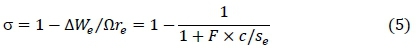
The coefficient, F, is the ratio of the sum of the average eddy-induced velocities on the suction and pressure surfaces, to that along the impeller exit rim. This coefficient depends on ße and Z, and has been developed further in successive papers by Von Backström [12, 13, 14] to improve the agreement between the SRE method and the numerical values from the two-dimensional analytical solution of Hassenpflug [3], henceforth called the BH data. The best empirical approximation was [13]:

As explained by Von Backström [14], the digit 2, outside the brackets in equation 6 ensures that F4 = 2 when ße = 90 °, resulting in excellent agreement with the BH data at high values of ße. A remark of Hassenpflug [3] that, for an impeller with 2 straight radial blades (cosße= 1.0), the inviscid flow slip factor should be exactly 1/2, led to further investigation. For RR = 0.5, and the conditions mentioned above, c/se = 1/ (2π), and so F must be equal to 2π to make F χ c/se equal to the integer, 1. This is achieved by replacing the (3/ Z) in equation 6 by the more meaningful (π /Z), the half angle between adjacent blades, and by replacing the 2.7 by (1.5 π-2). These substitutions allow us to rewrite F in terms of π as:

This empirical correction ensures perfect agreement with the BH data for 2 straight radial blades (ße = 0), and an error of 0.3 % for Z > 2. When Z = 1, the error is < 2.5 %. The comparative curve fit of Paeng and Chung [19] requires five equations for similar accuracy, and is not defined when Z = 1.
The current paper applies the SRE method to impellers with straight, back-swept blades, by making the initial assumption that the slip factor depends primarily on the blade solidity, as defined by the sum of the blade lengths divided by the impeller circumference. The initial objective is then to write the solidity for straight blades in terms of the number of blades, their exit angle and the radius ratio for straight, back-swept blades. As a first approximation the solidity influence coefficient, F5, as developed for logarithmic spiral blades is applied, and the resulting prediction compared to the experimental data.
The validity of the solidity as a primary variable that determines slip, has however been questioned by Huang et al. [20]. This really relates to the effect of radius ratio, RR, as it is the only relevant variable that appears in the solidity but not in its influence coefficient, F. This concern had been addressed in the SRE method by assuming RR = 0.5 whenever RR < 0 [12]. It implies that slip factor does not depend on solidity when RR < 0.5. It also assumes that the drop-off in slip factor at larger radius ratios starts at RR = 0.5 and that the drop-off rate is correctly predicted by the basic SRE method. This assumption needs reconsideration, however, as discussed later. To check the validity of the SRE method, its performance will be compared to that of other more recent data sets and prediction methods.
4 Objectives
The general objective of this study is to investigate the slip factor of impellers with straight, back-swept blades, and to develop a method to predict their performance. Specific objectives of the work are to:
1. Investigate the geometric peculiarities of straight-bladed impellers
2. Derive the SRE slip factor equations for the blade solidity of straight bladed impellers.
3. Compare predicted and published slip factors.
4. Select, design and manufacture a family of straight-bladed radial impellers.
5. Measure the slip factor of the family of straight-bladed back-swept impellers
6. Compare predicted and measured slip factors
7. Make recommendations regarding the use of the SRE and other methods for straight, back-swept blades.
5 Review of recent literature
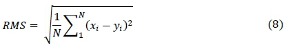
Slip factors predicted by the SRE method will be compared in terms of RMS differences, to those from four data sets published since the SRE papers. The RMS value of the difference between xt and yt for i = 1 to N is defined as:
The reference row in each of the tables below is the one showing the zero RMS difference. The objective is to gauge how well the SRE predicts slip factor compared to these data sets. Due to space constraints the prediction methods from literature are not discussed in detail.
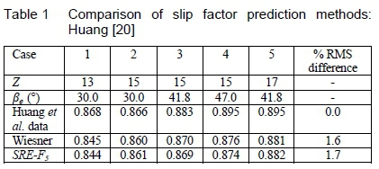
Huang et al. [20] used commercial centrifugal compressor software to design six impellers with 13, 15 and 17 blades with exit angles of 30, 41.8 and 47 °, and modelled their performance at mass flows from 80 to 120 % of the design flow, at zero tip clearance, using CFD. They investigated the effect of blade curvature, referring to a change in blade angle relative to the local radial direction along the blade length. They found that it could affect the variation of slip factor with flow rate, although, in their examples, the presented maximum variation in slip factor over their flow range is about 2 %. For the examples we could reproduce, the SRE predicted the slip factors, in terms of the root mean squared (RMS) value of the difference, to well below 2 %, as does Wiesner [9] (table 1).
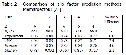
Memardezfouli and Nourbakhsh [21] compare various slip factor prediction methods to their measured data for five pump impellers. They compare the methods of Wiesner [9], Stodola [10] and Stanitz [11], as well as an early version of the SRE [12] and their own theoretical slip factor (TSF), which is a superposition of an axi-symmetrical meridional plane analysis and a blade-to-blade singularity method. Unfortunately they did not, in their application of the SRE method, correct the blade reference angle from radial to tangential (i.e. change cosines in the SRE equations to sines). The SRE equation they list under their table also has 1 - RR2 in it instead of 1 - RR. Table 2 shows the correct version of the SRE method, and compares, in the last column, the RMS differences. At their relatively large exit blade angles (60 to 72 °.) the SRE method agrees slightly better with their data than their own TSF method (2.1 % RMS difference compared to 2.4), with both showing deviations of about half of that of Wiesner [9].
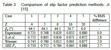
Ji et al. [15] developed a slip factor correlation for radial and mixed-flow impellers, based on the Euler turbo-machinery equation. It incorporates the dependence of slip factor on the flow coefficient to better represent experimental data. The relative eddy effect is introduced through a Stodola [10] type approach, where a circular eddy is fitted into each blade passage near its exit. The Stodola model is inaccurate for low blade numbers (Z < 16 and high blade angle (ße > 50°) (Von Backström, [14]). To this they then add the contribution the of blade curvature. Table 3 shows that the SRE with F5 does about as well as their method (2.7 % RMS difference compared to 2.8) with the Wiesner RMS difference even lower at 2.0 %.
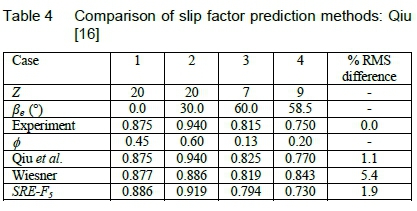
Qiu et al. [16] presented the development and validation of a slip factor model for design and off-design, similar to that of Ji et al. [15]. They incorporate the flow coefficient, φζ at the rotor exit to cater for off-design variation in slip factor, and present four test cases that can be used as benchmarks. The Eckardt [22] O and A rotors, as well as a pump and blower test case, all have relatively high sensitivity to flow coefficient. Their method, which is sensitive to flow coefficient, is very accurate, especially at mid flow range. The SRE method, does however capture some flow sensitivity when the slip factor is converted from our definition to that of Eckardt [22], as proposed by Ji et al. [15]. The predicted slip factor then varies from 0.90 for φ = 0.2, to 0.92 for φ= 0.6. For the blower case, RR was taken from the relevant figure as 0.67. For the four test cases in table 4 the RMS difference of 1.9 %, of the SRE method is 70% larger than the 1.1 % of Qiu et al. [16], but it is still relatively small and about one third of that of Wiesner [9].
In spite of being insensitive to flow coefficient, the SRE method performs consistently well (RMS difference of typically 2 %) compared to the recently published data and methods in the 19 test cases listed in tables 1 to 4. This establishes the use of an accurate, inviscid relative eddy model as a basis for a relatively accurate practical slip factor prediction method. It is therefore reasonable to consider it for impellers with back-swept straight blades too. As the method of Qiu et al. [16] is sensitive to flow coefficient, but insensitive to radius ratio, and is based on an extensive data set, it will also be applied. The equations used to calculate the Qiu et al. [16] slip factors are given in the appendix of their paper. For application here, they were simplified to remove the effects of disc coning (for mixed-flow impellers), blade thickness and fluid density ratio. The well-tried empirical method of Wiesner [9] on the other hand, is insensitive to flow coefficient but can account for radius ratio, so it will also be considered.
6 SRE slip factor for straight-bladed impellers
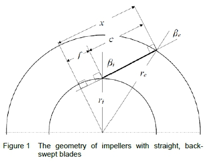
Figure 1 shows the geometry of a two-dimensional straight-bladed impeller. The blade angle at the outer radius re, is ße. The blade angle, ßi at the inner radius can be determined with the sine rule:
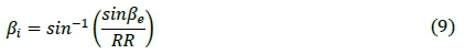
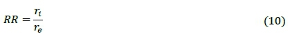
where the radius ratio, RR is defined as:
From the above, it is clear that βι is not defined if sinße /RR > 1 , since the straight blade will then not intersect the inner radius circle. This limits the possible blade exit angles to low values if RR is low, e.g. to 30° when RR = 0.5, as in this study. Conversely, the use of large back-sweep angles requires large values of RR. This implies that the critical radius ratio RRc where the slip factor starts dropping off, may be exceeded in many designs.
In figure 1 the blade chord length is then found by noting that the blade length, c = x - f with:
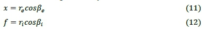
So:

The blade solidity at the impeller outer radius is the sum of the blade lengths divided by the rotor circumference. For straight blades it is:
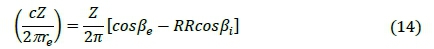
It has been shown before (Von Backström, [12]) that for logarithmic spiral blades the solidity is:

Note that for radial blades, when cosße = cosß = 1, both equations above result in a solidity equal to Z (1-RR)l(2n). From the solidity equations (13) and (14) above it follows that, for a given straight-bladed impeller geometry, the equivalent radius ratio of the logarithmic spiral bladed impeller with the same solidity is:

If this radius ratio, RReq is used, the logarithmic spiral SRE theory will render the same slip factor as the straight bladed SRE theory for a straight-bladed impeller with a particular number of blades and blade exit angle.
From equations 5 and 14 it follows that the SRE slip factor for straight bladed impellers is:
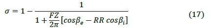
The intention is to use the coefficient, F = F5, equation 7 listed above.
7 Literature for straight bladed impellers
Straight, radial blades (ße = 0) can be classified as members of the logarithmic spiral family as well as of the straight blade family. Consequently they have already been incorporated into the development of the SRE and other theories in the literature. Apart from data on impellers with radial blades with no back sweep, no literature specifically addressing impellers with back-swept, straight blades could be found. An available data set of analytically determined, back-swept, straight bladed impellers, however, is that of Theodorsen [5, 6] as reported by Hassenpflug [3], henceforth called the TH data (geometry in tables 5 to 7). He presents graphs of the slip factor for two-dimensional inviscid flow against equivalent sparsity (the inverse of solidity) for three straight-bladed backswept impellers with 1 to 12, 1 to 14 or 1 to16 blades, representing 42 test cases in total. In figures 2 to 4 we compare the SRE slip factors, calculated with F5 against the real solidity, given by equation 14, extracted from the TH data.
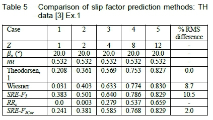
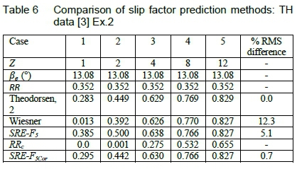
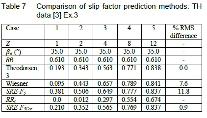
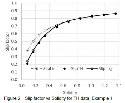
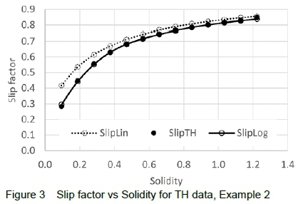
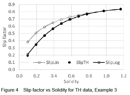
The top lines in the figures, designated by SlipLn, show that the SRE slip factors for straight blades using the unadjusted radius ratios, agree reasonably well with the TH slip factors for solidities above about 0.6 (representing 8 or more blades), but that the accuracy deteriorates rapidly at lower values. This indicates that a more accurate model for backswept straight bladed impellers with low numbers of blades is required. When figures 2 to 4 are overlaid (not shown) it also turns out that at the higher solidities the three sets of data coincide well, indicating that for high solidities the slip factor is indeed completely determined by the solidity and the unique influence coefficient, F.
The reason that the SRE does not agree well with the inviscid solutions for less than 8 blades (solidity = 0.7), is that according to the BH data, the drop-off in slip factor with radius ratio already starts at RR < 0.5 when Z < 8. It is however possible to correct for this effect. We propose the following simple, empirical procedure. First calculate the SRE slip factor with F5, for RR = 0.5. Then calculate the critical radius ratio RRc = 2σ -1, where the slip factor starts dropping with increasing RR. This follows from the observation that on the Busemann [4] graphs of slip factor vs. RR, that σ « 0.5+ RRc/2. The radius ratio correction coefficient is RRCF = (RR - RRc)/(1 - RRc). For RR > RRc, the coefficient, F5 is then multiplied by 1 - RRCF15. The exponent, 1.5 was chosen to blend the constant slip factor region smoothly with the drop-off region. The result is so good that SRE prediction and the TH data practically coincide, as seen in figures 2 to 4 and tables 5 to 7 (RMS differences of 2.0 %, 0.7% and 0.9 %). What is especially gratifying is that the standard SRE with this simple modification could almost perfectly represent all of the 42 straight-bladed impellers of the TH data set. The Wiesner RMS differences vary between 8 and 12 %.
An important finding is that the standard SRE method, with an RRc correction accurately models inviscid flow through two-dimensional impellers with any given number of straight back-swept blades. This is an important consideration for designers of series of impellers with varying numbers of blades.
8 Fan design, manufacture and testing
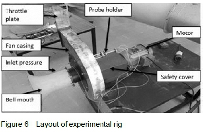
A series of simple test fans was constructed to gather experimental data on the slip factor of centrifugal impellers with straight back-swept blades. The rotor, volute and set-up are shown in figures 5 and 6. The fan inlet tube intrudes into the fan housing up to the impeller eye, leaving an axial gap of 1.5 mm (1 % of eye diameter). The fan casing and logarithmic spiral volute are 95 mm wide in the axial direction, and the volute width increases linearly in the radial direction from 10 mm at its start to 185 at its end, giving a volute angle of 72 ° (from radial). The start and end of the volute are exactly above the rotor axis when the fan is oriented such that the flow leaves the volute horizontally.
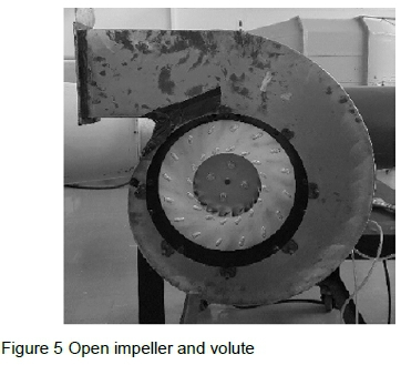
Each impeller consists of a 300 mm diameter circular, flat back-plate attached to the fan shaft, and a 300 mm front plate with a 150 mm diameter inlet eye. The blade leading edges are at the edge of the inlet eye, at 75 mm from the axis, and the trailing edges at the rotor rim at 150 mm radius, thereby fixing RR at 0.5. This is acceptable, as it is expected to have an effect only for the 4-bladed impeller, and the comparison with the TH data has already shown that the SRE method can handle variations in RR. The rear disc of the fan was made of 6 mm thick Aluminium plate and the front of 4 mm. The blade thickness is 2 mm. The laser cut blades have tabs that fit into laser cut slots in the front and back plates, and were welded to the plates on the outside. This ensures smooth, unobstructed flow channels. The internal width of the impeller between front and back discs is 40 mm. The blade inlet angles are 0, 50 or 70 ° with corresponding exit angles 0, 22.52 and 28.02 °. Each impeller has 4, 8 or 16 blades. The impellers were driven at 1500 rpm by a 1 kW electrical motor through a variable speed drive, resulting in a rotor rim speed of 23.6 m/s. Speed was measured at 1 second intervals with an electronic tachometer with an accuracy of ± 0.05%.
The flow through the fan was measured with a calibrated 150 mm diameter bell mouth nozzle with a discharge coefficient of 0.980. The fan exit velocity was measured at a radius of 158.5 mm exactly above the fan axis. The volume flow through the fan was adjusted by a plate throttle fitted to the flange at the end of the volute.
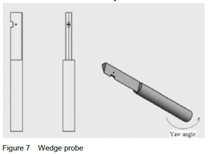
A wedge probe (figure 7) was used to measure the flow velocity magnitude and angle at ten points across the fan impeller width (figure 8). The probe was calibrated in a small wind tunnel against a standard Pitot tube, and had a velocity coefficient of 0.950. The pressure transducers had an accuracy of ±1% and a range of 1 000 Pa, and were calibrated against a Betz water manometer with an accuracy of 1 Pa.
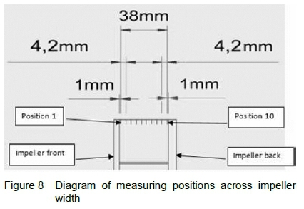
A null method was used to align the probe to the flow direction and determine the flow angle to an estimated accuracy of 1°. This measurement approach corresponds to that of Memardezfouli and Nourbahksh [21]. They found that the radial velocity components measured with a wedge probe like ours, at three different circumferential positions, agreed perfectly only at the nominal design flow coefficient (= 0.14) of the volute. The flow weighted average radial and circumferential velocity components were determined by numerical integration as presented by Memardezfouli and Nourbahksh [21]. Our integration width was 42.2 mm to allow for a 7.5 ° radial expansion angle per side of the jet leaving the impeller. The velocity components were then corrected to account for the difference between the radial position of the measuring station and the exit radius of the impeller, by considering the flow areas and conservation of angular momentum. It was found that the average mass flow balance between the bell mouth and the exit probe measurement was within 0.1 %, but the standard deviation of the difference was a relatively high 8.8 %. Since the circumferential velocity component was about four times as large as the radial component, a small error in measured angle has a large effect on the radial component, and virtually no effect on the circumferential component.
The measured slip velocity is calculated as the difference between the measured and ideal circumferential velocity components at the rotor rim:
The radial velocity component at the impeller exit is calculated from the volume flow as determined by the inlet nozzle.
9 Comparison of predicted and measured slip factors
Figures 9, 11 and 13 present measured and predicted slip factors for the impellers with 4, 8 and 16 blades, and a blade exit angle of 22.52 °. Figures 10, 11 and 12 relate to 8-bladed impellers with exit angles of 0.0, 22.52 and 28.02 °. Since the volute design corresponded more or less with an exit flow coefficient of 0.14, the measured slip factors are expected to be the most reliable near that value. The SRE method for the eddy-induced slip factor is not sensitive to flow coefficient, but the Qiu et al. [16] method predicts only a small effect for these cases, and the measured data show no clear trends for our data. The equations used to calculate the Qiu et al. [16] slip factors are given in the appendix of their paper. For application here, their equations were simplified to remove the effects of disc coning, blade thickness and fluid density ratio.
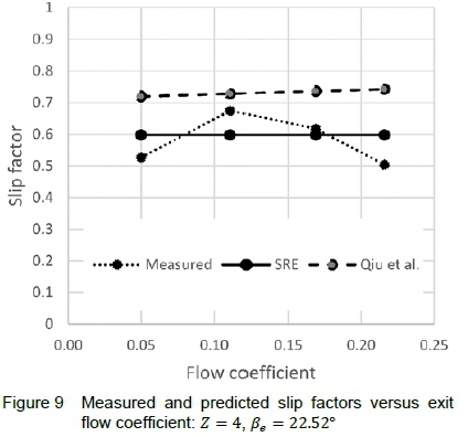
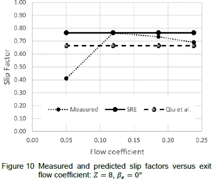
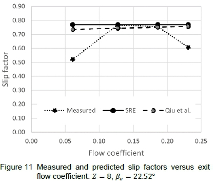
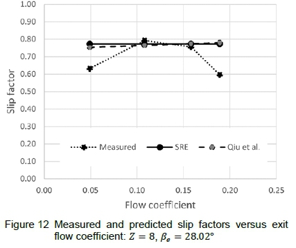
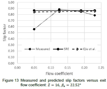
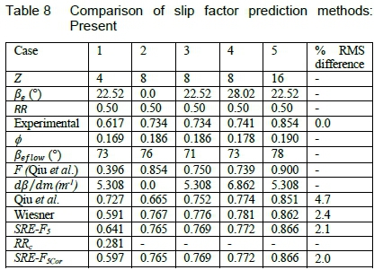
Slip factors and absolute flow angles at rotor exit for each fan are presented at the same four throttle settings. The flow angles agree more or less with the volute angle of 72 °. For each impeller the middle two flow coefficients resulted in more or less the same slip factor, with the one at the higher flow corresponding better with the design flow coefficient. For these cases (table 8) the RMS difference between experiment and prediction was 2.0 % for the SRE compared to 4.7 % for Qiu et al. [16] and 2.4 % for Wiesner [9]. Since the method of Qiu et al. is blind to the effect of radius ratio, it over predicts the slip factor for the low blade number of 4 in figure 9, where the critical radius ratio is less than 0.5. Also, since radial blades (ße =ß = 0) have no effective curvature, unlike back-swept, "straight" blades, the curvature term is zero, and so it under predicts in figure 10.
10 Conclusions
The equations for the SRE method applied to impellers with straight, back-swept blades have been derived. It was found that in straight-bladed impellers the possible exit blade angles are constrained by the impeller radius ratio. This means that when radius ratios are moderate to low, say below 0.5, the exit blade angle is then limited to a maximum of 30 °.
The previously published universal solidity influence coefficient in the SRE method has been slightly adjusted to achieve better numerical agreement with exact analytical data for two-dimensional inviscid flow through logarithmic spiral blades. Comparison with methods and measurements published since the previous SRE papers show that, in general the SRE method predicts slip factors with a typical RMS difference of about 2 %. This establishes the use of an accurate, inviscid relative eddy model as a basis for a relatively accurate practical slip factor prediction method, and questions in principle the use of the inaccurate Stodola relative eddy model as basis, before adding addition terms to account for flow variations and blade curvature.
A new radius ratio correction for cases with low numbers of blades ensures excellent agreement to the analytical prediction of slip factor for impellers with straight, backswept blades. The slip factor, as defined and used in these cases is independent of flow coefficient. A set of impellers with straight, back-swept blades was designed, manufactured and tested. It was found that their slip factors vary very little when the flow coefficient is close to the volute design flow coefficient. The SRE method predicts these slip factors to within 2 % RMS.
In general it is recommended that standard slip factor prediction methods be used for impellers with straight, backswept blades. For the range for radius ratio, blade number and blade exit angle of straight-bladed impellers, it turns out that accounting for the critical radius ratio is more important than to model the sensitivity to flow coefficient.
Acknowledgement
Stephen Ryall designed and installed the volute, and did the experimental work.
References
[1] R. I. Lewis. Turbomachinery Performance Analysis. Wiley, New York, 1996.
[2] F. C. Visser, J. J. H. Brouwers and R. Badie. Theoretical analysis of inertially irrotational and solenoidal flow in two-dimensional radial-flow pump and turbine impellers with equiangular blades. Journal of Fluid Mechanics, 269:107-141, 1994. [ Links ]
[3] W. C. Hassenpflug. The incompressible two-dimensional potential flow through blades of a rotating radial impeller. Mathematical and Computer modelling, 52(9-10):1299-1389, 2010. [ Links ]
[4] A. Busemann. Das förderhöhenverhältniss radialer kreiselpumpen mit logarithisch-spiraligen schaufeln. Zeitschrift fur Angewandte Mathematik und Mechanik, 8(5):372-84, 1928. [ Links ]
[5] T. Theodorsen. Theory of wing sections of arbitrary shape. NACA Technical report No 311, 1931.
[6] T. Theodorsen and I.E. Garrick. General potential theory of arbitrary wing sections. NACA Report No 452, 1933.
[7] R. H. Aungier. Centrifugal Compressors: A Strategy for Aerodynamic Design and Analysis. The American Society of Mechanical Engineers, New York, 2000.
[8] A. Whitfield and N.C. Baines. Design of Radial Turbomachines. Longman Scientific and Technical, UK, 1990.
[9] F. J. Wiesner. A review of slip factors for centrifugal impellers. Journal of Engineering for Gas Turbines and Power, 89(4):558-566, 1967. [ Links ]
[10] A. Stodola. Steam and Gas Turbines. McGraw-Hill, Reprinted by Peter Smith, New York, 1927.
[11] J. D. Stanitz. Some theoretical aerodynamic investigations of impellers in radial- and mixed-flow centrifugal compressors. Transactions of the ASME, 74:473-476, 1952. [ Links ]
[12] T. W. von Backström. A unified correlation for slip factor in centrifugal impellers, ASME Journal of Turbomachinery, 128(1):1-10, 2006. [ Links ]
[13] T. W. von Backström. A compact equation for the prediction of eddy-induced slip in centrifugal impellers, In Proceedings: Institution of Mechanical Engineers, Part A: Journal ofPower and Energy, 220(8): 911-915, 2006.
[14] T. W. von Backström. Relative-eddy induced slip in centrifugal impellers for engineering students. R&D Journal, 21(1):21-27, 2007. [ Links ]
[15] C. Ji, X. D. Ruan, P. Darlo. and X. Fu. A new correlation for slip factor in radial and mixed-flow impellers. In Proceedings: Institution of Mechanical Engineers, Part A: Journal ofPower and Energy, 225(1):114-119, 2011. [ Links ]
[16] X. Qiu, D. Japikse, J. Zhao and M. R. Anderson. Analysis and validation of a unified slip factor model for impeller design and off-design conditions. ASME Journal of Turbomachinery, 133(4), 2011. [ Links ]
[17] B. Eck. Fans. Pergamon Press, Germany, p. 37, 1973.
[18] G. T. Csanady. Head correction factors for radial impellers. Engineering (London), 190:195, 1960. [ Links ]
[19] K. S. Paeng and M. K. Chung. A new slip factor for centrifugal impellers. In Proceedings: Institution of Mechanical Engineers, Part A: Journal of Power and Energy, 215(5):645-649, 2001. [ Links ]
[20] J. M. Huang, K. W. Luo, C. F. Chen, C. P. Chiang, T. Y. Wu and C. H. Chen. Numerical investigations of slip phenomena in centrifugal compressor impellers. International Journal of Turbo & Jet-Engines, 30(1):123-132, 2013. [ Links ]
[21] M. Memardezfouli and A. Nourbaksh. Experimental investigation of slip factors in centrifugal pumps. Experimental Thermal and Fluid Science, 33(5):938- 945, 2009. [ Links ]
[22] D. Eckardt. Flow field analysis of radial and backswept centrifugal impellers, Part 1: Flow measurement using laser velocimeter. In 25th ASME Gas Turbine Conference and 22nd Annual Fluid Engineering Conference, New Orleans, 1980.
Received 26 September 2019
Revised form 4 November 2019
Accepted 2 December 2019

