


Services on Demand
Article
 English (pdf)
 Article in xml format
 Article references
Indicators

Related links
-
 Cited by Google
 -
 Similars in Google
Share

 Permalink
R&D Journal
On-line version ISSN 2309-8988
Print version ISSN 0257-9669
R&D j. (Matieland, Online) vol.35 Stellenbosch, Cape Town 2019
http://dx.doi.org/10.17159/2309-8988/2019/v35a6
ARTICLES
A parametric design and optimization approach to enhance the fatigue life of a male pyramid socket adapter
P.A. le RouxI; R.F. LaubscherII
IPhD student, Department of Mechanical Engineering, University of Johannesburg, South Africa. E-mail: pieterleroux@me.com
IIDepartment of Mechanical Engineering, University of Johannesburg, South Africa. E-mail: rflaubscher@uj.ac.za
ABSTRACT
This research paper presents a parametric design approach to optimize a male pyramid socket adapter as used on a transtibial prosthetic limb for enhanced fatigue life. These adapters are prone to premature failure when used by individuals partaking in athletic sports. A parametric design and optimization approach is presented and applied. A current design was assessed for structural integrity by finite element analysis in combination with the load criteria as recommended by the ISO 10328:2016 code of practice. Highly-stressed regions where identified and improved using a parametric design approach to reduce the maximum 1st Principal stress while adhering to the industry code of practice as applicable to pyramid socket adapter design. The optimization was validated by experimentally comparing the current design and the optimised design for an appropriate load case by low cycle fatigue testing. The socket adapters were manufactured from Ti6Al4V and subjected to a simulated resultant knee bending moment. The fatigue validation indicated a significant improvement in fatigue life for the optimized socket geometry commensurate with a reduction in stress and comparison to an appropriate SN curve for Ti6Al4V. The parametric optimization process as utilized was found to be effective and should be applicable to many different applications in a more general sense.
Additional keywords: Parametric design, Low-cycle fatigue testing, Transtibial prosthesis, Male pyramid socket adapter.
Nomenclature
PAD Peripheral arterial disease
SACH Solid-ankle-cushioned-heel
WHO World Health Organization
ISO International Organization for Standardization
FEA Finite Element Analysis
1 Introduction
As the average life span of the world's population increases due to advances in medicine and better living conditions, the need for artificial limbs is becoming more important (Ziegler-Graham, MacKenzie, Ephraim, Travison, & Brookmeyer, 2008). With modern medicine, amputations may in many cases be avoided since the risk of wound infection can be prevented, however the leg is still the most common site of amputation (Youngson, 2000). The most common cause of amputation in healthy patients is due to severe limb injuries/trauma to such an extent that the limb loses its functionality (National Health Services in England, 2014). The leading cause for amputations are due to Peripheral Artery Disease (PAD) caused by poor blood flow to the limbs as a result of narrowing arteries and the resultant blockage, that may result in gangrene, intractable pain or sarcoma in the bone, muscle or tissue of the limb (Johns Hopkins Medicine, 2015). PAD mostly occurs between the ages of 50 to 75 and is usually the result of diabetes or atherosclerosis (Johns Hopkins Medicine, 2015).
After an amputation and recovery period, the amputee can choose to fit a prosthesis to the residual limb. Modern prostheses can perform sophisticated tasks simulating natural limb movement to suite the patient's needs. However, adjusting to a prosthesis requires that the amputee undergoes an extensive course of physiotherapy and rehabilitation. The amputee also requires more energy to make use of a prosthesis as the residual limb has to compensate for the missing bone and muscle (Health Net, 2015).
A transtibial, below the knee, amputation is the most common amputation currently performed in medicine (National Health Services in England, 2014; Prosthetic & Orthotic care, 2015). Since the knee joint is preserved, the amputee can regain or exceed their activity level prior to limb removal.
A typical transtibial prosthesis, as seen in figure 1, consists of the following parts:
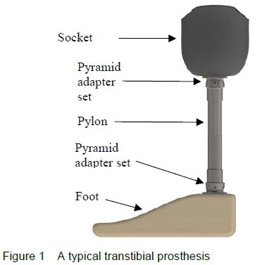
• Socket: The socket acts as the basic interface between patient and prosthesis. It is a moulded shape that consists of a rigid outer and soft inner shell that is sculpted to fit the residual limb. It is shaped to transfer the patient's body weight onto the prosthesis without injuring or causing discomfort to the patient. Most transtibial prostheses relies on localized suction to ensure the residual limb does not separate from the prosthesis.
• Pylon and modular components: The pylon and its modular components replicates the function of bones in human limbs (ROMP (Range Of Motion Project), 2015). These components are primarily made from titanium, stainless steel or aluminium, depending on the function and patient weight. Small adapter components, referred to as male and female socket adapters, at each end of the tubing, allow a prosthetist to adjust the alignment of the prosthesis to mimic the alignment of a biological limb. The pylon also connects the socket to the prosthetic foot.
• Foot: The human foot is one of the most complex limbs in the human body consisting of 26 bones, 33 joints and over 100 ligaments, muscles and tendons (Prosthetic & Orthotic care, 2015). Depending on the patient weight and activity level, a basic SACH foot can be prescribed for a patient with a low activity level, to a high-performance carbon fibre foot mimicking natural foot motion for high activity level patients.
The modular components used on both ends of the pylon to connect the residual limb to the foot typically do not change for adults during their lifetime but may change rapidly for children and teens during growth spurts affecting the prosthesis length and alignment. This change in prosthesis setup generates larger torsional and bending moments on the structural modular components which can lead to premature failure if the components are not adjusted or replaced to take into account the increased patient load regimes.
Taller and heavier patients are expected to have a reduced service life on prosthetic structural components as heavier patient loads and longer effective lengths results in higher bending and torsional stresses.
A study conducted in 2014 concluded that 13% of the adult population were obese and 39% were overweight (World Health Organisation, 2018). Data also indicate that the length of young adult men in Europe has increased by 11 cm during the last century (Hatton & Bray, 2010; Bogin & Varela-Silva, 2010).
Currently the minimum required service life of a lower limb structural component is 3 million load cycles per designed patient load as prescribed by the ISO 10328:2016 code of practice (ISO - International Organization for Standardization, 2016). Premature failure of structural prosthetic components is not uncommon mostly due to alignment issues during installation or patients partaking in athletic sports.
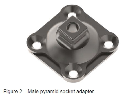
The male pyramid socket adapter, as seen in figure 2, is a universal prosthetic modular component used to connect a variety of structural components on a prosthetic limb. The male pyramid socket adapter is most commonly manufactured from either stainless steel or titanium alloy as required by patient load and activity levels.
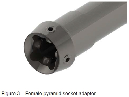
Typically a female adapter (figure 3) is attached to the male adapter by grub screws interfacing with the male adapter pyramid faces. A domed outer and inner surface ensures positive contact between the male and female adapters.
2 Typical socket adapter failure
Typical failure of the socket adapter was investigated by sourcing failed components from a prosthetics laboratory (Johannesburg, South Africa). The failed components were associated mostly with higher activity level sportsmen and included increased body weights than per normal. This along with an increased length, and therefore stride, had a negative effect on the fatigue performance.
A failure analysis was therefore conducted on selected prematurely failed components. Two failed components were investigated from a transtibial amputee that weighs approximately 100 kg and with a body height of 1.9 m. The two samples lasted between 3 and 6 months before an almost identical failure occurred. The samples were from different manufactures and were produced from stainless steel for a maximum patient load of 125 kg (Load level P6).
Figure 4 presents a typical example of a premature failure. Failure typically results due to alignment errors or overloading.
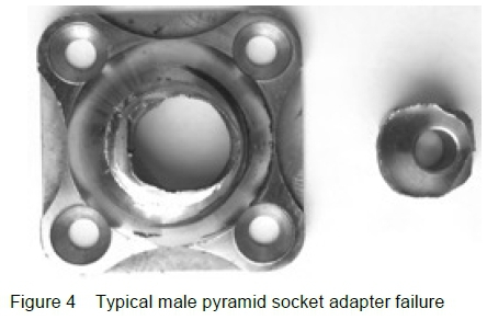
Over alignment of a pyramid socket adapter set can lead to premature failure that results in the separation of the pyramid apex and the domed section of the component.
Failure due to misalignment is typically indicated by the following:
• Indications of wear marks on both the pylon and pyramid adapter as a result of localised relative movement between the pyramid adapter on the pylon adapter's proximal end.
• Incomplete localised circular deformation on the convex domed surface of the pyramid adapter. Indicating that the adapter did not transfer the load through the correct load line.
• Excessive angular alignment beyond the assembly angle set by the pylon and pyramid adapter manufacturer. This may result in a gap between the pyramid and pylon adapter, resulting in additional stresses to certain areas of the pyramid apex.
• Incompatibility between pylon and pyramid adapter convex angle. Resulting in a reduced load contact surface area.
The failure analyses of both socket adapters indicated similarities in their method of failure. Neither of the two components failed as a result of misassembly, as none of the factors as outlined above, were immediately apparent on either of the components. Both failed due to fatigue. The transition line between the crack initiation and subsequent growth due fatigue to final fracture is indicated in figure 5.
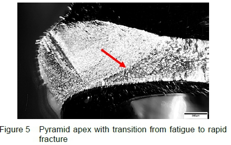
The fatigue surface on the anterior midline of the component was formed from a hairline crack that initiated on the anterior surface between the pyramid apex and domed section of the adapter. The crack propagated during cyclic loading through the anterior section of the component, weakening and thereby decreasing the load bearing capacity of the component that resulted in eventual fracture due to the crack reaching its critical length.
3 Parametric design optimization
3.1 Process
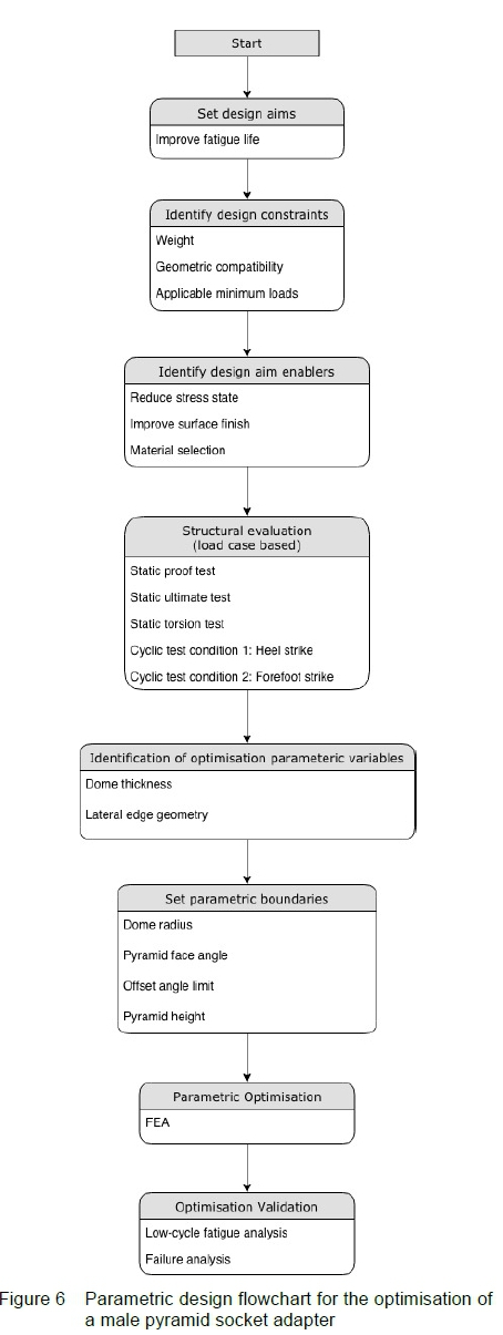
The parametric design process as conducted is presented as a flowchart in figure 6. It consists of a number of general steps that are then applied to the specific problem at hand (fatigue optimization of a pyramid adapter).
3.1.1 Set design aims
The first step is to set the specific aims for the design optimization. This may include aims such as weight reduction, improvement of structural integrity, improvement of fatigue life etc. The aim for the current process is to improve the fatigue life.
3.1.2 Identify design constraints
The design constrains are those factors that need to be taken into account during the optimization process. The design constraints for the current optimization include:
• To reduce or retain current component weight.
• Retain geometric compatibility with existing mating components.
• Utilize the applicable minimum load cases as suitable for an appropriate patient load.
3.1.3 Identify design aim enablers
The design enablers are those factors that may be considered for achieving the design aims. For the current optimization these include:
• Reduction in the overall stress state by geometric optimization.
• Improve surface finish.
• Alternative material selection or state.
The main enabler identified for the current optimization was identified as geometric optimization that results in a reduced stress state.
3.1.4 Structural evaluation (Load case based)
A structural evaluation of the adapter was conducted by Finite Element Analysis (FEA) based on the various load cases as identified in accordance to the ISO 10328:2016 code of practice. The structural evaluation was conducted to assess the current pyramid adapter performance when subjected to an appropriate maximum load case as recommended by the code of practice. The maximum load case currently described in the code is P8 which is commensurate with individuals with a maximum patient load of 180 kg. This maximum load case was also deemed more appropriate for large athletic individuals partaking in dynamic sports.
A FEA model with five load cases were created in accordance to the ISO 10328:2016 code of practice to simulate different load cases associated with normal operating conditions, these include:
1. LC1: Static proof test: The static proof test comprises of a compression axial load that is applied to either the prosthesis or its structural components in order to determine the maximum compression stress during normal operation. The maximum static proof test force for a load level P8 is 3200 N (ISO - International Organization for Standardization, 2016).
2. LC2: Static ultimate test: The static ultimate test is an extension of the static proof test with an increased axial load to determine whether plastic deformation occurs at the maximum compressive stress region of the component. The maximum static ultimate test force for a load level P8 is 4450 N (ISO - International Organization for Standardization, 2016).
3. LC3: Static torsion test: The static torsion test as defined by the ISO 10328:2016 is used to determine whether slippage and/or torsional shear will occur on the structural prosthetic components. A maximum static torque of 50 Nm is recommended for all load levels (including P8) as per ISO 10328:2016 code of practice (ISO - International Organization for Standardization, 2016).
4. LC4: Cyclic test condition 1 (Heel strike): The cyclic test condition 1 (heel strike) simulates the load condition for which the load travels through the heel of the foot, simulating a heel strike during walking. This cyclic condition is resolved from a single load vector into an axial force, two bending moments and a torsional moment about each lower limb joint simplifying the analysis about each joint.
5. LC5: Cyclic test condition 2 (Forefoot strike): The cyclic test condition 2 (forefoot strike) is a variation of cyclic load condition 1 where the load vector travels through the metatarsal head of the foot. Therefore, both cyclic testing conditions simulates either end of the walking process where the load line moves from the posterior to anterior of the prosthesis.
The FEA model setup had fixed boundary conditions at the base of the male pyramid socket adapter's four mounting holes, with the female pyramid socket adapter attached at 5 to 10 degrees of flexion in the sagittal plane, as is typically found in bench alignment of a transtibial prosthesis. The male and female adapters had a contact surface mount constraint on the domed surfaces with the bolted connections and interfaces set up as per the recommended torque requirements for the respective bolt sizes.
3.1.5 Identification of optimization parametric variables
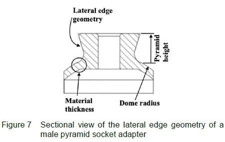
The lateral edge geometry and material thickness of the dome area were the two variables selected for optimisation of the socket adapter as depicted in figure 7. The primary focus was placed on the lateral edge geometry and pyramid apex as an increase in material thickness of the dome is associated with additional weight. However, as the lateral edge and apex geometry is altered through the parametric design process, the dome thickness at the pyramid apex is indirectly altered. Thus, the functional performance of the domed area can be altered indirectly through the optimisation of the lateral edge and apex geometry.
3.1.6 Set parametric boundaries
To achieve compatibility with mating prosthetic components, the following boundaries were defined:
• Dome radius: The dome radius needs to remain constant to ensure that mating components have maximum surface contact with the dome surface area. Maximum dome contact between mating components will ensure that axial loads aren't transmitted incorrectly through the pyramid apex as a result of misalignment.
• Pyramid face angle: The four contact faces of the pyramid need to remain at the correct mating angle range relative to the female pyramid socket adapter's setscrews to ensure compatibility. Changing the pyramid angle can result in an insufficient alignment range, that could affect the overall performance of the male pyramid socket adapter.
• Offset angle limit: The offset angle has to be limited to accommodate the existing female pyramid adapter components that interact with the male pyramid adapter. Generating excessive offset angles may reduce the fatigue performance of mating components.
• Pyramid height: Cannot exceed a certain height as it will result in a misassembly of the prosthetic socket interface.
3.1.7 Parametric optimisation
A parametric geometric optimisation was conducted by FEA for all of the five criteria as set out by the ISO 10328:2016 code of practice (ISO - International Organization for Standardization, 2016).
3.1.8 Optimisation validation
The optimised geometry design was then validated by conducting high stress in-plane bending fatigue testing and comparing the original and optimized design.
3.2 Parametric optimisation by FEA
The parametric optimization was conducted by comparing the structural integrity of the initial design (design iteration 1) with three other design iterations (2,3,4) when subjected to the 5 different load cases. Optimization was deemed successful when the 1st Principal stress component was reduced to 570 MPa ± 5% (to account for a variation yield strength values from multiple material batches). This stress value is commensurate with a fatigue life of approximately 3 million cycles when subjected to a "pulsating tension" R=0 fatigue load (Peters, et al., 2002) that is typically associated with walking loads (LC4 and LC5). Linear elastic (E = 115 GPa, ν = 0.31) FEA was conducted utilizing second order tetrahedral elements with local refinement as appropriate. The loading and boundary conditions were externally applied to commensurate with the load case in question (le Roux, 2017).
3.3 Parametric optimisation iterations
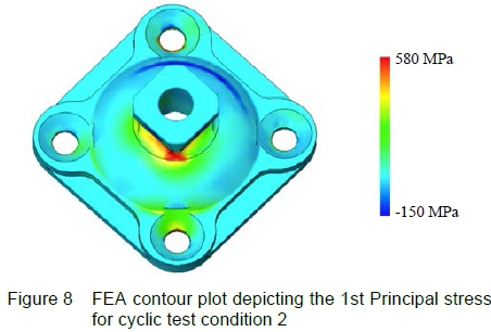
The cyclic load cases LC4 and LC5 subjected the part to the most severe stress states. The FEA results indicated that the part experiences a high tensile stress at the region between the four-sided pyramid apex and the domed surface of the male pyramid socket adapter in the diagonal direction along the pyramid lateral edge (see figure 8). This high tensile stress region was as a result of the resultant knee bending and torsion moment.
3.3.1 Parametric design variable selection
A parametric design variable was identified to optimise the pyramid geometry at the pyramid apex to dome interface to reduce the stress concentration formed at the pyramid's lateral edges. The original design had a flattened region (visible in figure 2) where the pyramid apex morphed into the domed section of the part. The rest of the component was used as the start for each parametric pyramid design.
Three parametric design iterations were analysed before sufficient improvement was obtained to reduce the first principal stress below 600 MPa. Figure 9 presents the variation of the maximum first principle stress as a function of the various design iterations for all 5 load cases. Design iteration 1 represents the initial design.
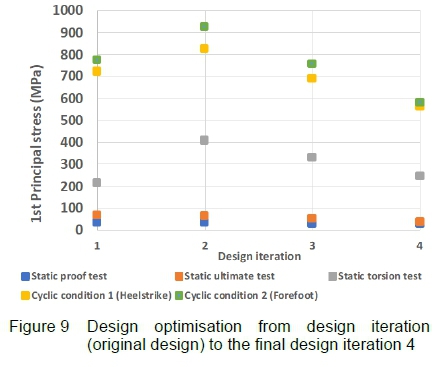
1. Conical pyramid apex (design iteration 2): This design made use of a conical pyramid design that morphed from the domed surface into the cylindrical pyramid apex. In the end this design's FEA results indicated higher tensile stresses due to the lack of a lateral pyramid apex support required when experiencing the resultant knee bending moment during both cyclic conditions.
2. Splined hemispherical pyramid (design iteration3): This design made use of a hemispherical and splined dome that morphs into the domed area, increasing the diagonal width of the pyramid apex without affecting compatibility. The FEA results indicated a slight decrease in the first principal stresses in comparison with the original design.
3. Filleted hemispherical pyramid (design iteration 4): Building on the previous design, the spline was replaced by a fillet of 5mm. Increasing the hemispherical height of the dome and increasing the size of the lateral edges of the pyramid. The optimised design reduced the maximum first principal stress from 774 MPa, for the original design, to 578 MPa during a forefoot strike. This indicates a 196 MPa reduction in stress or a 25% improvement.
4 Optimisation validation
4.1 Experimental design
Depending on the type of fatigue loading applied the reduction in stress level as obtained by the optimization should result in an appreciable increase in fatigue life. The complexity of the multiaxial loads and moments involved in both cyclic test load cases cannot be readily duplicated in practice due to the required complexity of the experimental setup. The results would also be difficult to associate with the available fatigue data for Ti6Al4V. As a result, a fully reversed in-plane bending moment was applied to the male pyramid socket adapter to simulate a heel to forefoot strike's resultant knee bending moment along the lateral edge of the four-sided pyramid. An appropriate bending moment (150 Nm) was applied to achieve a similar stress state via simple in plane bending at the location of maximum stress as indicated by the structural evaluation and commensurate with the values obtained for load case 5. According to the available fatigue data for Ti6Al4V this load case would result in an estimated fatigue life of less than 100 000 cycles (Peters, et al., 2002) that would be readily achievable with the equipment at hand and is also probably be a better indicator of fatigue improvement for situations where the components are subjected to severe loadings as associated with large individuals partaking in athletic sports.
4.2 Specimen manufacturing
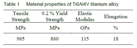
Ti6Al4V (ASTM B348:2009) round bar (75 mm) was used to produce 6 specimens (3 original design and 3 design iteration 4 samples). The mechanical properties as per the material certificate are presented in table 1.
The manufacturing process were as follow:
• Initial roughing of the billet was conducted on a CNC lathe at the conventional recommended cutting speeds for Ti6Al4V (56 m/min) utilising coated tungsten carbide tool with a 80° rhombus Sandvik (CNMG 12 04 08-XF GC15) C-shaped insert with a nose radius of 0.8 mm at a cutting depth of 0.25 mm.
• Finishing was conducted on the outer geometry at the conventional recommended cutting speeds of 40 m/min utilising coated tungsten carbide tool with a 55° rhombus Sandvik (DNMG 15 06 12-SMC 1115) D-shaped insert with a nose radius of 1.2 mm at a cutting depth of 0.2 mm.
• The internal dome geometry was machined at 30 m/min utilising coated tungsten carbide tool with a 55° rhombus (DCMT 07 02 02-KF H13A) D-shaped insert from Sandvik with a nose radius of 0.2 mm at a cutting depth of 0.25 mm.
• The lateral faces of the pyramid were machined on a NC milling machine using a 5 mm tungsten carbide ballnose milling cutter at 30 m/min. Convention flood cooling was used throughout.
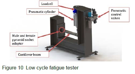
4.3 Fatigue machine
A custom-built low cycle fatigue machine was developed to simulate the resultant knee bending moment. The machine utilises pneumatics to generate the required forces. A closed loop control system was developed to perform the following functions:
• Measure and control applied force by direct feedback control of a set of pneumatic control valves at 100 Hz;
• Counts the number of load cycles experienced;
• Displays machine state on a LCD display;
• Send force, time and cycle data to a data logger at 10 ms intervals;
• Hosts a local network webpage to display current machine state, statistics of the current sample and a force vs. time data; and
• Automatically stops the system once a failure is detected.
The frame of the machine was constructed from I-beam sections and welded into an L-shape. A 16 mm plate was used to mount the loadcell and pneumatic cylinder to the machine frame. A rod-eye at the end of the pneumatic cylinder connects to the free-end of the cantilever beam, with the opposite end consisting of a female pyramid socket adapter bolted to the male adapter with 4 grub screws. The male adapter is then secured through its base to a 12 mm mounting plate located at the opposite end of the L-shaped machine frame. A digital mock-up of the machine is presented in figure 10.
5 Results
The results of the fatigue life testing are presented in table 2. The data shows that significant improvement in fatigue life was achieved for the optimized design (design iteration 4). On average an improvement of nearly threefold (2.9) was achieved with similar part weights. The optimized design was 0.4 g (0.6 %) lighter.
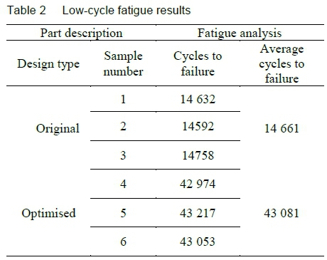
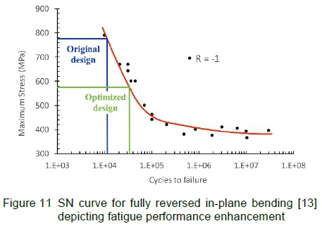
Figure 11 presents the results of the fatigue test data compared to material fatigue data (Ti6Al4V) as presented by Peters et al [12]. Good correlation is achieved with similar fully reversed stress amplitudes indicated by the material data as was applied experimentally. The results indicate that a fatigue life of approximately 3 million cycles should be achievable for the optimized design when subjected to the P8 load level for a "pulsating tension" R = 0 fatigue load (Peters, et al., 2002).
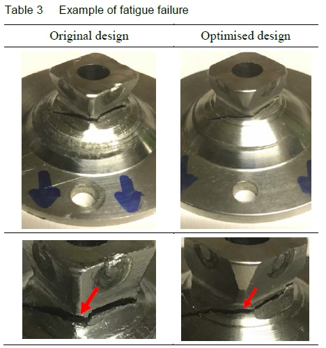
Examples of failed components (both original and optimized designs) are presented in table 3. Both samples had a crack initiation site at the lateral edge, near the apex, of the pyramid that propagated towards the centreline of the component. Crack propagation was observed inwards towards the 8 mm hole in the centre of the component before final fracture occurred.
6 Conclusion
A design optimization scheme based on a parametric approach is presented. It is then applied to optimize the fatigue life of a male pyramid socket adapter as utilised in a transtibial prosthesis. The structural geometry was optimized for a maximum patient load as recommended by the code of practice without affecting compatibility and weight. The net result is a reduction in the maximum first principal stress by 196 MPa and therefore enhancing the component's fatigue performance by approximately 290 % as demonstrated by a fully reversed low cycle fatigue test. The successful application of the scheme implies that it may be applied successfully to a wide range of mechanical parts and/or components catering for a wide range of design aims.
References
[1] K. Ziegler-Graham, E. J. MacKenzie, P. L. Ephraim, T. G. Travison and R. Brookmeyer. Estimating the prevalence of limb loss in the United States: 2005 to 2050. Archives of Physical Medicine Rehabilitation, 89(3):422-429, 2008. [ Links ]
[2] R. Youngson. The Royal Society of Medicine Health Encyclopedia. Bloomsbury, London, 2000.
[3] National Health Services in England. Introduction to amputations. URL www.nhs.uk/conditions/amputation/Pages/Introduction.aspx, 2014.
[4] Johns Hopkins Medicine. Health Library: Amputation. URL www.hopkinsmedicine.org/healthlibrary/testprocedures/cardiovascular/amputationprocedure 92,P08292/, 2015.
[5] Health Net. National Medical Policy: Myoelectric Prosthesis. URL www.healthnet.com/static/general/unprotected/pdfs/national/policies/MyoelectricProsthesis.pdf, 2015.
[6] Prosthetic & Orthotic Care. Transtibial Prosthetics. URL http://www.pandocare.com/transtibial-prosthetics/, 2015.
[7] ROMP (Range Of Motion Project). Lower Extremity Prosthetics. URL http://www.rompglobal.org/prosthetics-101.html, 2015.
[8] Prosthetic & Orthotic Care. Prosthetic Feet. URL http://www.pandocare.com/prosthetic-feet/, 2015.
[9] World Health Organisation. Obesity and Overweight. URL https://www.who.int/en/news-room/fact-sheets/detail/obesity-and-overweight, 2018.
[10] T. J. Hatton and B. E. Bray. Long run trends in the heights of European men, 19th-20th centuries. Economics and Human Biology, 8(3):405-413, 2010. [ Links ]
[11] B. Bogin and M. I. Varela-Silva. Leg length, body proportion, and health: A review with a note on beauty. International Journal of Environmental Research and Public Health, 7(3):1047-1075, 2010. [ Links ]
[12] ISO 10328:2016. Prosthetics - Structural testing of lower limb prostheses - Requirements and test methods. ISO -International Organization for Standardization, 2016.
[13] J. O. Peters, B. L. Boyce, X. Chen, J. M. McNaney, J. W. Hutchinson and R. O. Ritchie. On the application of the Kitagawa-Takahashi diagram to foreign-object damage and high-cycle fatigue. Engineering Fracture Mechanics, 69(13):1425-1446, 2002. [ Links ]
[14] P. A. Le Roux. Fatigue performance optimisation of a transtibial prosthetic socket adapter. M.Eng Thesis, University of Johannesburg, Johannesburg, South Africa, 2017. [ Links ]
Received 2 April 2019
Revised form 5 November 2019
Accepted 11 November 2019

