


Services on Demand
Article
 English (pdf)
 Article in xml format
 Article references
Indicators

Related links
-
 Cited by Google
 -
 Similars in Google
Share

 Permalink
R&D Journal
On-line version ISSN 2309-8988
Print version ISSN 0257-9669
R&D j. (Matieland, Online) vol.34 Stellenbosch, Cape Town 2018
Composite tube testing and failure theory computational comparison
M. NarsaiI; S. AdaliII; K. VealeIII; J. PadayacheeIV
ISAIMechE Student Member. Discipline of Mechanical Engineering, Centre for Composite Materials and Structures, University of KwaZulu- Natal (UKZN), South Africa, narsai.mikhail@gmail.com
IIDiscipline of Mechanical Engineering, Centre for Composite Materials and Structures, UKZN, South Africa, adali@ukzn.ac.za
IIISAIMechE Member. Discipline of Mechanical Engineering, Centre for Composite Materials and Structures, UKZN, South Africa, kirsty_veale@hotmail.com
IVSAIMechE Member. Discipline of Mechanical Engineering, UKZN, South Africa, PadayacheeJ@ukzn.ac.za
ABSTRACT
Composites are used in lightweight structural designs. This paper describes experimental tests conducted on composite tubes and a comparison with computational results. A test method was developed which involves an applied axial compressive load on tubes fabricated using Unidirectional (UD) carbon fibre set at +35°, to induce compressive and shear stresses along thefibres. Four major failure criteria were compared against test results: Tsai-Wu, Hoffman, Tsai Hill and Maximum Strain. The Hoffman and Tsai-Wu criteria were shown to be accurate and conservative. The Tsai-Hill criteria produced high strength ratios. The Maximum Strain criteria had the highest strength ratio, proving to be the least conservative and deviated most from computational results. This paper shows that the Hoffman and Tsai-Wu failure criteria may be used confidently in applications such as filament winding and continuous pultrusion methods, which are widely used in producing closed sections. Additionally, elastic and shear moduli were varied in simulations to show that small inaccuracies in those properties do not substantially change the maximum failure index output.
Additional keywords: Finite Element Analysis, Destructive Testing, NX Nastran
1 Introduction
For the failure analysis of composite structures an important consideration is the availability of accurate data for material properties, in particular, data for the elastic constants and strength properties. In practice, fabrication and testing of panels to obtain this information can be difficult, expensive and possibly with some inaccuracies due to manufacturing tolerances [1]. Imperfections in the layup can further complicate an accurate prediction of failure and these may not always be avoidable. The effect of uncertainties in the ply properties on the failure evaluation has been noted in [2]. Another consideration is the selection of an appropriate failure criterion since different criteria may predict failure accurately in different cases [3, 4]. It was observed in a number of studies that the predictions of most theories differ significantly from the experimental observations" [5, 6]. It was further noted in [5] that "many of the existing failure models could not predict the experimental response within a tolerable limit. In fact, differences of up to an order of magnitude between the predicted and experimental values were not uncommon." These observations indicate the importance of the accurate assessment of failure of composites by determining the materials properties accurately and identifying the applicable failure criterion for a specific application.
The objective of this study is to assess the accuracy of composite failure theories as applied to composite tubes by producing a test method that loads the fibres in Carbon Fibre Reinforced Polymer (CFRP) tubes in compression and shear. The results shed light on the sensitivity of the results to specific failure theories. This allows a more reliable design approach for composite tubes using appropriate failure criteria. Such tubes are used extensively in space frame chassis designs [7, 8]. In the present study the effect of uncertainty in the material properties on the failure loads was studied using four different failure criteria.
The specific composite studied in the present work is CFRP (Carbon Fibre Reinforced Plastic) which is often the material of choice in the design of a composite space frame chassis due to its high strength and stiffness as well as low weight [9]. Fibre composite materials are studied extensively in the books by Nijssen [10] and Kaw [11] where it is pointed out that the superior performance of CFRP in terms of its low mass, high strength and high stiffness as compared to other materials.
In the present study, an experimental study of composite tubes are complemented by finite element analyses to compare the test and numerical results. In particular, the Nastran direct sparse solver within NX is used for this purpose. Analysing simple geometries can be done analytically but accurate results for complex cases can be obtained via a Finite Element Analysis (FEA) through FEA packages with composite analysis tools. It is noted that composite tubes are used extensively.
2 Failure Criteria
There are several theories and methods to analyse and predict composite laminate failure [12]. These methods, in general, differ substantially in their approaches and can produce varied results with some showing differences of the final failure (total fracture and separation) stress of up to 970% as tested by Soden et al. [13]. NX Nastran software can use various criteria to determine failure, including Tsai-Hill, Hoffman, Tsai-Wu, and Maximum Strain. The following information regarding the processing of the failure criteria by NX and NX Nastran is sourced from the NX Laminate Composite Student Guide by Siemens [14].
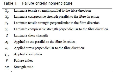
The notation relating to the failure theories is shown in Table 1. Note that for normal stresses, positive values indicate tension.
In the Tsai-Hill failure criterion, the first term uses Xcif compression is applied, and XTif tension is applied. The second term uses XTif the applied stresses have the same sign, and Xcif they have different signs. The third term operates in a similar fashion to the first term.
The Hoffman failure criterion is described as follows:

and

The strength ratio is obtained by multiplying each stress term by the strength ratio (Si?) and setting F equal to one then solving the quadratic equation. The smallest positive root should be considered.
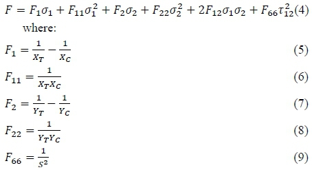
The Tsai-Wu failure criterion is described as follows:

F12 is user-defined, but is set as zero if the following equation is not satisfied:
The strength ratio is calculated in the same way as in the Hoffman theory. The interaction term F12must be determined experimentally through biaxial testing [15]. Narayanswami and Adelman [16] expressed that setting the interaction term as zero provides adequate accuracy for engineering purposes in fibre reinforced composite materials loaded bi-axially.
Their testing consisted of ten composite combinations and six loading conditions and maximum error in predicted loads was under 10%. Note that setting the interaction term to 1/XCXT reduces the Tsai-Wu theory to the Hoffman theory [15].
Cui et al. [17] explored using various values for the normalised interaction term defined as follows:

Their study focused on delamination, so their final value of 0.7 for the normalised interaction term may not apply to this paper, and Tsai and Hahn [18] described the normalised interaction term acting in a similar way to the von Mises criterion in ductile materials.
3 Methodology
For the experimental part of the study, composite specimens were tested in order to determine their elastic constants and strength properties. Values obtained from tests were compared to corresponding results available in the literature to ascertain their accuracy. Next, an experimental test was designed to stress fibres in a tube in compression and shear. Compression and shear tests were chosen, as it is a common scenario found in space frame chassis design. The test was then simulated using NX Nastran and the results were compared to the experimental results to validate the FEAs and compare failure criteria. Furthermore, a parametric analysis was conducted to study the effect of uncertainties in the elastic constants on the failure loads.
Testing was completed at the Durban University of Technology (DUT) Composites Technology Station. 12K 300 GSM UD carbon-fibre cloth manufactured by Gurit Holding AG (product code R163-040) was laid up and vacuum infused with Prime 20LV resin and slow hardened under a 100 kPa vacuum. The tests on the specimens were conducted in accordance with relevant ASTM standards as follows:
• Tensile test and elastic modulus in accordance with ASTM D3039 (0° and 90°) [19]
• Compressive test in accordance with the Modified D695-15 (0° and 90°) [20]
• Shear strength test in accordance with the ASTM D3518 [21]
• Shear modulus test guided by the ASTM D3518 [16]
• Matrix digestion test in accordance with the ASTM D3171-15 [22]
A micrometer was used to measure the shortening of the specimens during the loading.
3.1 Composite Tubes Testing
The goal of this test was to validate FEA results using a simplified but universal test. To simulate a member under compression and shear loading, the following test was designed. A tube was fabricated from UD cloth and its stacking sequence was specified as [+35°/+35°], relative to the loading axis (a line running the length of the tube, see figure 1). By testing the specimen in compression, the fibres experienced a combined load of compression and shear due to the angle, thus including more terms in failure criteria expressions and testing the theories more fully. Compression and shear stresses were observed during FEAs. Elements' axial stresses in the fibres' primary directions were always negative, indicating compression. Specimen geometry was chosen such that buckling was not a failure mode. The 35° angle was chosen to induce a ratio of compressive stress to shear stress of about 1.5, without weakening the tube in the axial direction such that it would fail in the wrong mode. Figure 1 illustrates the way the fabric was cut observing the 35° angle to the fibre direction.

Two layers of fibre were used per tube to increase the specimen thickness and to avoid buckling. An approximate diameter and an approximate wall thickness were chosen such that the possibility of buckling would occur at a much higher load than the predicted laminate failure load. UD fabric and the same angle for both plies were used to eliminate interlaminar shear so that the initial failure would quickly lead to final/ultimate failure. This removes the need for a transient, non-linear damage analysis. The plies were laid up on a polished aluminium mandrel. The layup was vacuum infused to maintain the same properties as the flat test specimens so that the properties from the tests can be used in the numerical simulation of the tests. Infusion and cure conditions were identical to the conditions of the previous flat panels.
It was observed that the surfaces of the tubes were wavy as shown in figure 2. This was caused by the vacuum bag process, which compressed the fibres to a point where they pleated. This was observed during the vacuum process. Because this was laid up on a mandrel, the inner surface did not show any waviness at all. This waviness implied that the tube thicknesses were inconsistent, and that there were small stress concentrations rather than uniformity throughout. However, failure zones were observed to occur at the thinnest part of the tubes.

Three tubes were tested in compression. Sandpaper was used at the top and bottom of each specimen to prevent slip and end crushing. In addition, a collar was used at the bottom to ensure a fixed rotation condition at that end. The top did not have a collar. Figure 3 shows this setup.

3.2 Finite Element Simulations
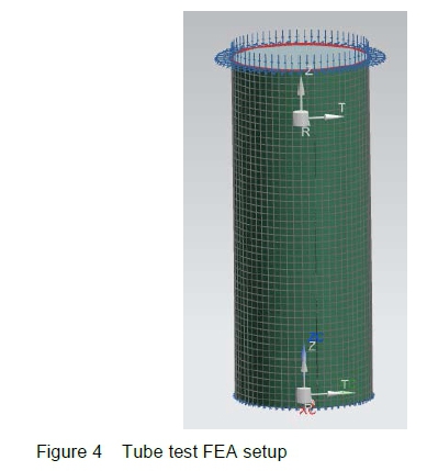
A finite element analysis was conducted using NX Nastran to compare computational and experimental results. Finite element models consisted of 1 mm CQUAD4 elements for accuracy. Each test had the geometry and ply thickness changed to match the experiment. Because the inner diameter was measured, the reference plane was set to "BOTTOM" from the default "MIDDLE". When the Tsai-Wu failure criterion was selected, the interaction term was set to zero. At the lower end of the tube where the collar was located, the mesh was fixed in translation and rotation. At the top, translation was fixed in the horizontal plane and rotation was only allowed about the local angular coordinate. The force applied to the top is the failure load obtained from the compressive test. Figure 4 shows the meshed geometry with the loads and constraints present. The model was translationally and rotationally fixed in all axes at the bottom edge and translationally fixed radially at the top edge. Maximum deformations were below 0.6 mm.
4 Testing and Associated FEAs
This section details the comparison of the results obtained by finite elements and experiments. This way numerical results can be directly compared with the experimental results. Furthermore, failure criteria are also compared with each other.
Flat panels were tested to determine the properties of a single UD ply which are required to compute a failure index. In this way, layups may include a ply-by-ply analysis which applies to any continuous fibre layup including strategically cut fabric in a hand-layup, pultrusion and filament winding. After these tests, a test was designed to induce axial loading and shear loading with respect to the fibre direction so that failure criteria could be tested under combined loading. These tests were then compared to FEAs simulating the experiments to validate the results and compare the failure criteria against each other. For each specimen, an FEA was conducted using the physical parameters of that specimen, as well as its failure load. Buckling FEAs were also carried out to ensure that first buckling mode eigenvalues were well above 5 (to account for imperfect geometry) to ensure that buckling was not a failure mode.
4.1 Laminate Property Testing

Laminate shear strength is the in-plane shear strength corresponding to the in-plane shear modulus. The results of the flat specimen tests are summarised in table 3 alongside the results from Bru et al. [23]. Matrix digestion tests showed that flat panels and tubes had an average fibre volume fraction of approximately 58%, which is close to the 60% specified by Bru et al. [23]. Variation in this volume fraction from panel to panel causes an error when all values are used together for a single panel, specimen or ply. Note that the coefficient of variance is abbreviated to CV. For the present tests, five samples contributed to each result as per ASTM specifications.

Strength values were close, but modulus values showed significant differences. The results for all except G12 were consistent and carried out to standards. It is possible that disagreement in G12 is due to scissoring in shear tests and the utilisation of a non-standard method to obtain the in-plane shear modulus.
4.2 Cylindrical Specimen Testing
Experimental testing of the fabricated tubes produced results which are compiled in Table 4. The collar length was 9.57 mm.

Failure was seen as a crack that propagated along the 35° of the fibres from about 8 mm from the top, but sometimes propagated across the fibres before continuing along the 35° angle to about 12 mm from the bottom.
5 Failure Criteria Comparison
The measurements and failure loads from the tubes were used to run FEAs to compare the failure criteria discussed in section 2, namely, Tsai-Wu, Hoffman, Tsai-Hill and Maximum Strain. For each failure criterion, a corresponding FEA was run with the output being the strength ratio.
For these simulations, strength ratios of slightly more than one are expected for two reasons. The first is that the waviness on the surfaces of the tubes may cause stress concentrations that could lead to premature failure. The second reason is that the average wall thickness is the value used in the simulation to match the amount of fibre in the real tube, but the failure regions on the tubes were in the areas that were thinner than the average wall thicknesses. Another finite element analysis of buckling was performed using the minimum wall thickness measured as the wall thickness parameter. The results again showed that failure should occur well before the buckling load is reached.
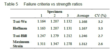
Table 5 shows a comparison of failure criteria using strength ratios for each specimen. Figure 5 illustrates the deformation and failure regions of the tube as predicted by the FEA. Red indicates the lowest strength ratio (which corresponds to the failure zone) and blue indicates the highest strength ratio.

As described, the specimens' cracks went along the tube, but are assumed to have started at the top as this is what is predicted by the FEA.
The most conservative theory was found to be Hoffman. The variation in results between the theories is similar, indicating that they are all equally sensitive to the loading conditions. Since specimens failed at the loads used in the FEAs, the strength ratios can be used as an error estimate of the theory.
It is noted that the average wall thickness was used in the FEA. However, failure occurred first in the thinner areas caused by waviness. Secondly, the value of G12 was found to be lower in comparison to the values found in the literature. Bru et al. [23] obtained a value of 4 400 MPa. Murakami and Matsuo [24] obtained a value of approximately 5 000 MPa for a lower fibre volume fraction of carbon fibre. A data sheet used by ACP Composites [25] presents a value of 5 000 MPa.
Using the minimum thicknesses, and a value of4400 MPa for G12, further FEAs were conducted for all three specimens. The results given in Table 6 show that tube failure is still predicted most accurately by the Hoffman criterion. The strength ratio is close to 1, and the "error" percentage has dropped to 2.2%. This provides validation for using tested material properties except for G12, which is set to 4400 MPa.

These results show that the Hoffman criterion is the most accurate and most conservative criterion for the tested tubes. This criterion is closely followed by the Tsai-Wu failure criterion which is also conservative and accurate.
5.1 Material Property Sensitivity
FEAs were carried out to assess the errors that may be present due to the errors in the tested material properties. This was done by altering certain material properties individually in the same FEA process as the FEAs done in the previous section. Specimen 3's dimensions (as per Table 4) were used as a reference, and the Hoffman criterion was used. The material properties that were significantly different from the properties obtained by Bru et al. [23] were tested, namely,
• E - elastic modulus (E11 and E22 only)
• NU - Poisson's Ratio (NU12 only)
• G - shear modulus (G12 only)
All other properties were held constant while the properties of interest were tested. Altering E11 yielded almost no variation in the strength ratio (Si?). This is likely because it is already very large in comparison to other stiffness values, making E11 stiffer did not increase its loading very much. Even a 50% increase in E11 only changed SR by 1.1%. A change in SR was observed when E22 was varied, and it required over 10% of variation of E22 to cause a 5% variation in SR. Changes in NU12 had very little effect on SR. Varying NU12 by over 40% resulted in a 1% variation in SR. This helped to warrant the use of NU12 = 0.28 from Bru et al. [23] in the FEAs conducted in this paper. Varying G12 by over 10% resulted in changes of SR by 5%. Increases in G12 lead to an increased strength ratio.
Finally, a simulation was run in which E11, E22 and G12 were changed to the values from Bru et al. [23] to examine the combined effect. The result shows a 5% increase in SR, implying that it is further from predicting the failure. This confirms that the minimum wall thickness played a significant role in the accuracy of the FEAs compared to the reliability of the material properties.
6 Discussion
The Hoffman and Tsai-Wu failure criteria showed good correlation with adjusted FEA simulations, thus confirming their ability to accurately predict failure in the application of UD laminate tubes. The Tsai-Hill and Maximum Strain criteria were observed to deviate most from computational results, and because they do not err on the side of caution, they should not be used for failure analysis of the present tests. Computational results were shown not to be exceptionally sensitive to mechanical material properties so long as moduli are measured with reasonable accuracy. Safety factors for future designs should be incorporated based on the uncertainty of the material properties, although for small uncertainties, the effect on the failure prediction is small. The waviness on tubes' surfaces creates uncertainty during testing, however, FEAs using the tubes' smallest diameters provide accurate results.
Simulations involved change in moduli but not change in strength values. Using NX or graphical methods, one can vary strengths or use a failure envelope to gain a perspective on how the strength affects the failure prediction.
Note that the analyses in this paper include compressive and shear stresses. No conclusions can be drawn with regard to tensile stresses.
7 Conclusions
Finite element and experimental results were compared for composite material tubes made of CFRP with respect to material failure. Failure criteria implemented in the comparisons involved Tsai-Wu, Hoffman, Tsai-Hill and Maximum Strain. Experimental study involved the testing of composite tubes with a 35° fibre angle to compare with finite element results. It was observed that Hoffman and Tsai-Wu criteria predict the failure loads more closely as compared with the experimental failure values. Maximum Strain and Tsai-Hill criteria were observed to produce higher strength ratios.
In the present study UD fabric was vacuum infused with resin in the present study to produce test specimens. In future studies other methods such as filament winding and continuous pultrusion can be used to study the effect of processing on the failure of the specimens.
Acknowledgements
The research reported in this paper was supported by research grants from the University of KwaZulu-Natal (UKZN) and from National Research Foundation (NRF) of South Africa. The authors gratefully acknowledge the supports provided by UKZN and NRF.
References
[1] M. J. Hinton, A. S. Kaddour, and P. D. Soden. Failure Criteria in Fibre Reinforced Polymer Composites, Elsevier, Oxford, 2004.
[2] A. Mukherjee, R. Ganguli, S. Gopalakrishnan, L. D. Cot, and C. Bes. Ply level uncertainty effects on failure of composite structures. In 7th European Workshop on Structural Health Monitoring, Nantes, France, 8-11 July 2014.
[3] N. Jauhari, R. Mishra, H. Thakur. Failure analysis of fibre-reinforced composite laminates. Materials Today: Proceedings, 4(2): 2851-2860, 2017. [ Links ]
[4] R. Talreja. Assessment of the fundamentals of failure theories for composite materials. Composite Science and Technology, 105:190-201, 2014. [ Links ]
[5] M. J. Hinton, A. S. Kaddour, and P. D. Soden. A comparison of the predictive capabilities of current failure theories for composite laminates, judged against experimental evidence. Composites Science and Technology, 62(12-13):1725-1797, 2002. [ Links ]
[6] C. G. Davila, P. P. Camanho, and C. A. Rose. Failure criteria for FRP laminates. Journal of Composite Materials, 39(4):323-345, 2005. [ Links ]
[7] A. More, C. Chavan, N. Patil, and K. Ravi. Design, analysis and optimization of space frame chassis. International Journal of Engineering and Technology, 9(2):1411-1422, 2017. [ Links ]
[8] J. Denny, K. Veale, A. Adali, and F. Leverone. Conceptual design and numerical validation of a composite monocoque solar passenger vehicle chassis. Engineering Science and Technology, an International Journal, 21(5):1067-1077, 2018. [ Links ]
[9] X. Yang, Y. Bai, F. J. Luo, X. L. Zhao, and X. H. He. Fiber-reinforced polymer composite members with adhesive bonded sleeve joints for space frame structures. Journal of Materials in Civil Engineering, 29(2): 04016208, 2016. [ Links ]
[10] R. P. L. Nijssen. Composite Materials: An Introduction. Inholland University of Applied Sciences, 2015.
[11] A. K. Kaw. Mechanics of Composite Materials. Taylor & Francis Group, Florida, 2nd edition, 2006.
[12] R. Satheesh, G. N. Naik, R., and Ganguli. Conservative design optimization of laminated composite structures using genetic algorithms and multiple failure criteria, Journal of Composite Materials, 44(3):369-387, 2010. [ Links ]
[13] P. D. Soden, M. J. Hinton, and A. S. Kaddour. A comparison of the predictive capabilities of current failure theories for composite laminates. Composites Science and Technology, 58(7):1225-1254, 1998. [ Links ]
[14] Siemens. NX laminate composites - student guide. Publication number mt15029-s-nx85: Siemens Product Lifecycle Management Software Inc, 2012.
[15] C. T. Sun, B. J. Quinn, J. Tao, and D. W. Oplinger. Comparative evaluation of failure analysis methods for composite laminates. Washington D.C: United States Department of Transportation, Federal Aviation Administration Office of Aviation Research, 1996. [16] R. Narayanaswami, and H. M. Adelman. Evaluation of the tensor polynomial and hoffman strength theories for composite materials. Journal of Composite Materials, 11(4):366-377, 1977. [ Links ]
[17] W. C. Cui, M. R. Wisnom, and M. Jones. A comparison of failure criteria to predict delamination of unidirectional glass/epoxy specimens waisted through the thickness. Composites, 23(3):158-166, 1991. [ Links ]
[18] S. W. Tsai, and H. T. Hahn HT. Introduction to Composite Materials. Technomic Publishing Company, Pennsylvania, 1980.
[19] ASTM D3039 / D3039M-14, Standard test method for tensile properties of polymer matrix composite material, ASTM International, 2014.
[20] ASTM D695-15, Standard test method for compressive properties of rigid plastics, ASTM International, 2015. [21] ASTM D3518 / D3518M-13, Standard test method for in-plane shear response of polymer matrix composite materials by tensile test of a ±45° laminate, ASTM International, 2013.
[22] ASTM D3171-15, Standard test method for constituent content of composite materials. ASTM International, 2015.
[23] T. Bru, P. Hellström, R. Gutkin, D. Ramantani, and G. Peterson. Characterisation of the mechanical and fracture properties of a uni-weave carbon fibre/epoxy non-crimp fabric composite. Data in Brief, 6:680-695, 2016.
[24] T. Murakami, and T. Matsuo. In-plane shear properties of carbon fiber reinforced thermoplastic composites by using V-notched specimen and digital image correlation. In 20th International Conference on Composite Materials. Copenhagen, 19-24 July 2015.
[25] ACP Composites, Mechanical properties of carbon fiber composite materials. URL www.acpsales.com/upload/Mechanical-Properties-of-Carbon-Fiber-Composite-Materials.pdf.
Received 14 December 2017
Revised form 25 Jun 2018
Accepted 9 November 2018

