


Services on Demand
Article
 English (pdf)
 Article in xml format
 Article references
Indicators

Related links
-
 Cited by Google
 -
 Similars in Google
Share

 Permalink
R&D Journal
On-line version ISSN 2309-8988
Print version ISSN 0257-9669
R&D j. (Matieland, Online) vol.34 Stellenbosch, Cape Town 2018
ARTICLES
Time-accurate transonic CFD Simulation of a generic store release case
D MacLucasI; IMA GledhillII
IASC, DPSS, CSIR, South Africa. DMacLucas@csir.co.za
IIASC, DPSS, CSIR, South Africa. IGledhil@csir.co.za , and School of Mechanical, Industrial and Aeronautical Engineering, University of the Witwatersrand, South Africa
ABSTRACT
Store release from a parent aircraft in the transonic regime is a complex transient interaction to simulate, due to both compressibility effects and the strong interference flow field generated between the parent and store bodies. This work presents the results from a time-accurate transonic numerical simulation of a generic store release case, with detailed attention to ejector force profiles. Confidence limits for time-accurate trajectory calculations with STAR-CCM+® have been improvedfor this standard benchmark case.
Additional keywords: Store separation, store integration, CFD, time-accurate
Nomenclature
Roman
d store diameter [m]
p,q,r store angular velocities with respect to the body fixed axes [rad s-1]
ρ pressure [Pa]
T time [s]
u,v,w store translational velocities relative to the flight axis and given in the direction of the body fixed axes [ms-1]
ν fluid velocity [ms-1]
X store orientation with fins at 45° to the pylon vertical plane
A cross-sectional area of the store body [m2]
AEDC Arnold Engineering Development Center
AIAA American Institute of Aeronautics and Astronautics
ASC Aeronautic Systems Competency Area CA axial force coefficient []
CFD Computational Fluid Dynamics CG centre of gravity
CLL store roll moment coefficient, positive with top fins rotating outboard []
CLM store pitching moment coefficient, positive nose up []
CLN store yaw moment coefficient, positive nose outboard []
CN normal force coefficient []
Cp pressure coefficient []
CTS Captive Trajectory System
CY side force coefficient []
DPSS Defence, Peace, Safety and Security
DRDB Defence Research and Development Board
ERU explosive release unit
F store forces [N] in the (Xb, Yb, Zb) system
GB gigabytes
ICAS International Council of Aeronautical Sciences
LC store length [m]
M store moments about the moment reference centre [Nm] in the (Xb, Yb, Zb) system
NACA National Advisory Committee for Aeronautics
NASA National Aeronautics and Space Administration
RAM random access memory
X,Y,Z displacements of store CG relative to flight axis system from store CG at carriage [m]
XL X from nose of store [m]
6DOF six-degree-of-freedom
Greek
αs store angle of attack [°]
θ store pitch angle, positive nose up [°]
ρ density [kgm-3]
φ store roll angle, positive with top fins rotating outboard [°]
ψ store yaw angle, positive nose outboard [°]
Subscripts
B body-fixed axes, origin fixed to the store CG
F flight axes, origin at the store CG in the carriage position below the pylon
S store
∞far-field conditions
1 Introduction
Transonic store integration programs generally require wind tunnel testing using Captive Trajectory Systems to determine both carriage loads and the safety of the store separation trajectory from the parent aircraft. CTS testing in a transonic wind tunnel incurs significant costs, due to the operation of the tunnel and the complexity of the CTS experiment. Numerical simulations are increasingly being used as an element incorporated within the system of tools for the transonic store integration process [1], where they are ideally suited to account for compressibility. Fully transient simulations have a role in complementing grid-mode calculations, in which trajectories are calculated using a 6DOF solver using simulation data of the steady-state store/parent interference flow field as well as store free-stream characteristics, which populate a lookup table for the store loads [2]. Neither the CTS (pseudo-steady) nor the grid-mode numerical simulation approaches are time-accurate, and therefore they do not account for the inherent unsteadiness encountered by the store during separation. This work provides a validation of generic time-accurate simulations with the overset code STAR CCM+®, for the purpose of benchmark validation and estimation of confidence limits.
Stores released vertically are forced away from the ejector rack suspended on the pylon by ERUs. ERUs have been incorporated in the present work, and the effects of the initialisation of the stores are contrasted with results from a previous study in which experimental initialisation was used [3]. This paper describes a test widely regarded as an accepted benchmark case (Lijewski, 1991 [4]).
In the transonic regime, CFD plays a role of detecting potentially dangerous shock configurations [1], and is part of the system of clearance for flight test and store integration.
1.1 Experiment
The wind tunnel test was performed at the AEDC closed-loop continuous flow 4T tunnel, with the objective of obtaining pressure and flow visualization data for a wing, pylon and store in mutual interference conditions, for carriage and in a realistic trajectory [5]. The test section is 4 ft (1.2192 m) square and is enclosed by variable porosity walls, in which the open fraction varies from 0.5% to 10%. The test parent is a 45° clipped swept wing based on the NACA04A010 section, with a pylon and an axisymmetric tangent ogive centre body sting support. Three store models were used: a "pressure" store with a sting and with 228 pressure tap orifices; a "metric" store, with a sting balance for force measurements; and a dummy store placed on the wing opposite the metric or pressure store for aerodynamic symmetry, for which the base was an axisymmetric ogive. The pressure store or the metric store was mounted with the fins in the "x" configuration (figure 1).

The store consists of a tangent-ogive forebody, a cylindrical centre body, and a tapered tangent-ogive afterbody with a truncated base; the four clipped fins are based on the NACA0008 section with a 60° leading edge sweep. The pylon axis is aligned with the flight axis. Geometry and coordinate systems are shown in figure 1. Dimensions for the AEDC experiment are provided in the original avoirdupois units for consistency with earlier publications (table 1, table 2 and 3).
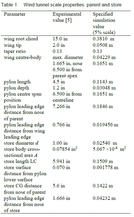
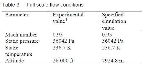
Flow conditions are provided in table 3.
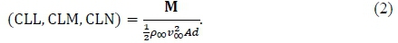
Where appropriate, metric values are shown to the precision to which they were specified in the simulation, for purposes of reproducibility. It is important to note that, although the experimental geometry was scaled to 5% of full scale, the CTS dynamic model used full scale parameters. Tests were conducted at Mach 0.95 and 1.20, but data are only available for the former value. The parent-store was at 0° angle of attack and 0° angle of yaw. Store coefficients are calculated from forces and moment coefficients are calculated from moments about the moment reference at the centre of the store as
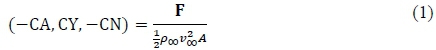
and
No transition trips were used, but the experiment report [5] indicates that transition did occur on the store, sometimes in the far aft region. The store was initially located on the pylon by touch points. Both store and parent measurements were corrected for sting deflection. Pressure measurements were repeated with the store at 45° rotations and on both sides of the parent wing. Experimental uncertainties were derived from these measurements. Under all conditions considered here, the sideslip angle of the parent was zero. The CTS method is quasi-stationary, but a correction to the angle of attack and yaw angle is provided to model the dynamic motion of the CG. Constant pitch, yaw and roll damping coefficients may have been assigned in the CTS case, but are not necessary in CFD since aerodynamic damping is already present in the loads. It is important to note that in all CTS trajectory cases, it was assumed that the ejector line of action was through the store centre line, ensuring that the store would not roll due to the ejector applied forces. In both CTS and simulation, the store was allowed to roll throughout the ejection and flight solely due to the aerodynamic forces. Mass and moments of inertia of the store remain constant during the test. No base pressure transducer appears to have been included for implementation of base pressure corrections. Additional details may be obtained from the report by Heim [5] and the data presented by Fox [6].
1.2 CFD studies
The benchmark case has been frequently used to validate CFD models of mutual interference and trajectory calculation, and this is the primary reason that we publish the current results as a validation for the use of STAR CCM+ ® in aerospace applications. The case has been referred to throughout store separation literature, notably by Lijewski, 1991 [4] and Lijewski and Suhs, 1992, 1994 [7, 8], Jordan, 1992 [9], Jordan et al., 1995 [10], Newman and Baysal, 1992 [11], Barbero and Ferretti, 1994 [2], Nichols et al., 1997 [12], Prewitt et al., 2000 [13], Snyder et al., 2003 for dynamic unstructured grids [14], Buning et al., 2004, for OVERFLOW [15], Lijewski for the BEGGAR and PEGASU S/DXEAGLE overset codes [16], Koomullil et al., 2008 [17], for polyhedral meshes, and Shih [18]. Additional validations will be found in later literature [19, 20, 21]. These time-accurate studies are based on Euler simulations, since the CTS results do not scale with the Reynolds number. Panagiotopoulos and Kyparissis [22] modelled the case for Mach number 1.2 with success for times up to 0.8 s. It is of later interest to note that Jordan, 1992, applied boundary conditions which incorporated the AEDC perforated wall corrections [9].
Euler simulation of the benchmark case was reported by MacLucas and Gledhill [3]. In this case, ejectors were not modelled. The store was placed in the flow at the end of the ejector stroke, and the experimental parameters for conditions at this time were used to initialise the trajectory. In the CFD model, hexahedral cells were used. This work is the current reference for the benchmark case for the overset mesh with 6DOF for STAR-CCM+ ® [23]. In contrast, in the present study, emphasis is placed on the modelling of the ejectors.
2 Numerical model
The wind tunnel tests do not scale with Reynolds number, since no turbulence tripping at suspected transition locations was attempted. Because the CTS calculations are made for full scale geometry in the experiment, the choice was made to simulate with CFD at full scale geometry, and inviscid assumptions were made. NACA airfoil sections were generated with NASA algorithms which allowed fine resolution to be obtained [24, 25, 26]. The CTS sting was excluded in order to test the comparison of a typical production CFD case with the benchmark, although it is noted that a sting with the diameter of the store base has been included in some simulation cases with success [7, 8, 12]. The solution domain, discretized using polyhedral cells, consists of two grids: the background grid which contains the parent and a high resolution release corridor, and the overset grid which contains the store. The Chimera embedded grid methodology [15, 23] is implemented in the CFD solver STAR-CCM+® [8].
A 6DOF solver was incorporated by the code authors to integrate the rigid-body equations of motion after each time step of the flow solver. Interpolation between the two grids was performed using a distance-weighted interpolation scheme [27]. The Euler angle transformation definitions for the store rotation may be found in Heim [5] and are applied in the order yaw, pitch, roll (ψ, θ, φ). Far field boundaries were set at distances from the model such that the ratio of the length of the domain (in X) over the root chord of the model is greater than 26 and the ratio of the cross-flow length of the box over the mid-span is greater than 7.
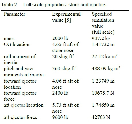
To match the CTS system algorithm in the experiment, the line of action of each ejector force is effectively applied through the axis of symmetry of the store body, and the forces exerted by the ejector pistons at the two contact points are applied as forces and moments at the store CG. This constitutes a marked difference with flight tests, in which the ejector line of action may be off-centre and cause significant roll. Note that a severe nose-down pitching moment exists in carriage [8], and therefore the aft ejector force is four times larger than the forward one (table 2). The forces are applied as the store surface travels through the length of the stroke of the ejector pistons in the Z direction, specified as 0.10 m. The ejectors are fired simultaneously. Each ejector is disabled once the displacement in the Z direction from the starting position of the store in carriage exceeds the ejector stroke length.
For comparison purposes, note that the CTS data is pseudo-steady, while the simulation is time-accurate. Similarly, no damping coefficient calculations were included in either the experiment or the simulation. Drag on the store was incorporated in both the experiment and the numerical model. It is not clear whether sting corrections were applied in the experimental method, but no sting is used in the simulation, in contrast to some other works [8]. The parent was constrained to be stationary during the simulation.
The implementation in STAR-CCM+® v.9.06 was used for the simulation [27], running on a cluster of 24 i7 quad-core nodes with 16 GB of RAM each. A second-order upwind Weiss-Smith scheme with the preconditioned Roe's flux-difference splitting scheme [27] was used to capture discontinuities adequately.
A second-order temporal scheme was employed for the transient solutions with a time step of 200 μs and with 15 inner iterations for the release stage of the simulation. The carriage configuration was initially allowed to reach steady state convergence of the force coefficients, which occurred over 10 ms.
3 Results
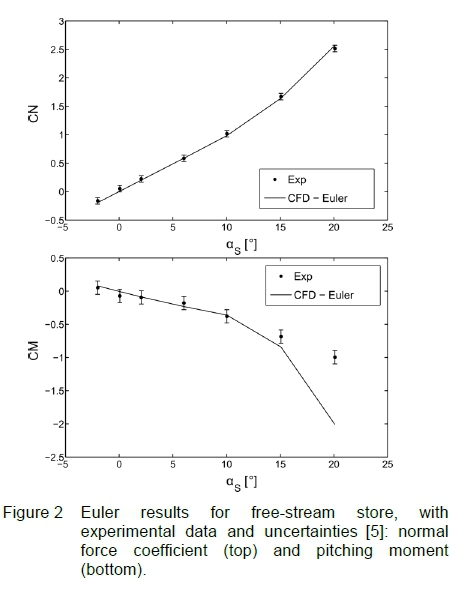
The free-stream results for the store in the x-configuration indicated that CN was predicted well over the store angle of attack (as) range, while the free stream pitching moment CM was well predicted for |as| < 10° (figure 2), after which viscous models are required. The subsequent trajectory results show that the angle of attack and yaw angle stay within this range as the store travels thorough the near field of the interference flow, defined as 2 to 3 diameters from the parent [2], taking about 0.3 s.
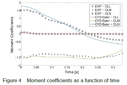
store force and moment coefficients during the trajectory are shown as functions of time in figure 3 and figure 4. Note that simulation results are for a full-scale inviscid time-accurate trajectory while experimental results are for sub-scale viscous quasi-steady trajectory with full-scale CTs calculations. Agreement between the two datasets therefore indicates that the model is a reasonable approximation, while differences may arise due to transient effects, scale effects, or viscous effects.
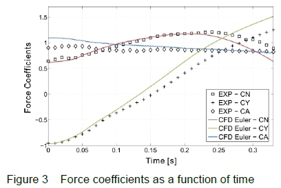
The Euler prediction of the normal force coefficient CN agrees closely with the experimental data during the critical time in which the store separates from the parent, before time t ~ 0.2 s.
The side force coefficient CY gradually diverges from the experimental results, with a difference ACY ~ 0.25 by 0.3 s, while the axial force coefficient CA shows the largest differences in the initial 0.05 s of the interval modelled. During this time, the store is launched with a nose-up attitude, and the ejectors exert part of the force experienced in the X direction. In contrast, a simulation without the ejector models exhibited significant transients in CN and CY as the trajectory was initialised at 0.05 s, as well as significantly overestimated values of drag.
In the published results, side force is predicted in slightly closer agreement with the experimental results when a section of the sting is included in the CFD model [8,12]. It is likely, therefore, that the divergence of CY seen in figure 2 is due to the absence of the sting.
The pitching moment coefficient CLM is in reasonable agreement with experimental values over the trajectory; the severe nose-down pitching moment in carriage is captured well, in contrast to previous Euler studies [10] and models without ejectors [3]. The differences in the carriage yaw moment coefficient CLN are smaller than those observed in early simulations [8, 10]. All differences in yaw moments are smaller than those in the corresponding simulation without an ejector model, especially as the time increases past 0.25 s. Jordan [9] and Nichols and Tramel [12] attained the closest correlation with the experimental data at carriage, when comparing full scale inviscid time-accurate simulations with the experiments.
Velocities are shown in figure 5 and figure 6.
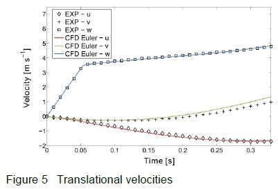
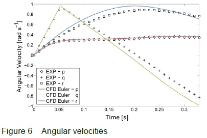
Ejector cutoff is responsible for the sharp velocity changes at t ~ 0.05 s. The agreement between predicted and experimental linear velocities is very good, and the outboard velocity v is in considerably better agreement than models without ejectors [3]. The store is initially pitched nose-up, and yaws outboard. The nose-down pitching moment starts to predominate, and at approximately 0.2 s the yaw rate changes sign to nose inboard. It is of interest that this change is better predicted when ejectors are not present, while pitch rate is in closer agreement when ejector models are used in the current model.
Displacements of the CG are shown in figure 7.
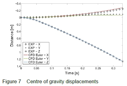
As expected, the CG motion is dominated by inertial effects rather than aerodynamic effects. In comparison with a model without ejectors [3] the vertical displacement prediction is considerably improved.
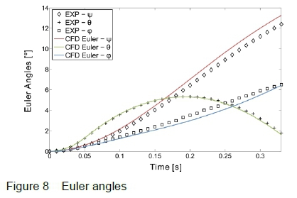
Roll, yaw and pitch (φ, ψ, θ) are well predicted in comparison with experiment (figure 8). A number of other authors publish angular displacements as the most significant criterion of acceptance of validation for this case. Prewitt et al. [13] show slightly larger differences between a Chimera simulation and experiment than are obtained here. If ejectors are not applied in our current simulation, pitch is slightly over-predicted, and yaw is significantly underpredicted.
Insight into the store loads can be gained by considering pressure coefficients Cp, where

An illustrative set of pressure coefficients as functions of distance along the upper surface of the store is shown in Figure 9 for circumferential angle 5°. The parameters XL and LC are given in table 1. It is also useful to note from table 1 that XL/LC = 0.28 at the pylon leading edge, which coincides with the inflection point of the ogive nose, and XL/LC = 0.72 at the leading edge of the store fins. The pylon trailing edge is aft of the store base.
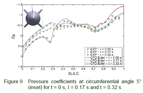
In carriage, for t = 0 s, agreement between computation and experimental data is good. The low pressure footprint of the pylon can be observed on the on the upper surface of the store. At XL/LC ~ 0.28, Cp falls near the stagnation at the leading edge of the pylon, and a shock is observed. At 0.6 ≤ XL/LC ≤ 0.7 the leading edges of the store fins are in close proximity to the pylon, and differences between simulation and experiment appear: since this is an Euler simulation, and the full scale gap is ~ 3.5 cm, it is possible that the correct simulation of this effect should include boundary layer and shock-boundary layer effects.
Inspection of Mach number surface plots reveals a compression structure, probably a weak shock, present at this position (figure 10).
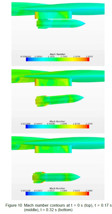
Aft of the fins, the flow expands over the store boat tail as expected. At 0.17 s, the store is at approximately maximum pitch (~ 5.0°), similar yaw (~ 5.3°), and has rolled slightly (~ 2°) (figure 8). The pressure footprint is reduced as expected. A shock is distinctly visible at the fin leading edge position in the simulation; the change in Cp at XL/LC ~ 0.28 is attributed to expansion over the surface inflection. By t = 0.32 s, the store is leaving the aircraft influence field; pitch is decreasing (~ 2.5°) and the store is yawing nose outboard (~ 12°) and rolling the top fins outboard (~ 6°). The shock at the leading edge of the fins persists and is in agreement with the possible indication of a shock in the experimental data.
4 Conclusions
As part of a programme to assess the confidence limits of the 6DOF time-accurate modelling of store separation using the code, STAR-CCM+®, we have presented results from an Euler model of a widely-used benchmark case [4] with models of the ejectors as specified, and compared these with previous CFD results. The STAR-CCM+® model is measurably improved, in comparison with the original experimental data, by the inclusion of the ejector models. Although this model is inviscid, it provides practical results for this case over much of the critical period of separation within 0.3 s of release. Forces and moments, velocities, and displacements are well predicted throughout the simulation. As expected the Z displacement, in particular, shows closer prediction of the experimental values than the simulation without ejector initialisation. Pitch angles are very well predicted by the present model while yaw is slightly overpredicted, as was the case in the earlier simulation. Comparison with results previously published in the literature by other authors is very good. We have also provided a detailed analysis of pressure coefficient results on the upper surface of the store, which are not usually published by other authors, and which are in good agreement with experimental data and indicate improvements in the simulation of flow in the gap at carriage as discussed below.
Several factors have an influence on numerical data comparisons for all models of this benchmark. First, it is noted that results calculated with the inclusion of a sting model, faired off at the aft end, provide better drag estimates [8, 12], and this is one of the next steps in the evaluation of confidence limits. Secondly, the contrast has been made between the quasi-stationary CTS results and the time-accurate numerical model. Work on quasi-stationary grid mode models of STAR-CCM+® is under way for comparison. Thirdly, the reasons for the deviations include the inviscid approximation of the numerical simulation. Inspection of the pressure coefficients at carriage indicate that when the store is in the carriage position, shock and boundary layer effects in the small gap between the pylon and the store surface could be better modelled using viscous and possibly turbulent flow. Viscous effects also occur in the free-stream store flow field as the angle of incidence exceeds ~ 10°; this range is reached toward the end of the time interval simulated here, where body vortex formation and flow separation become significant as the store leaves the near field range of the interference flow region. The natural step that is next in this process is the inclusion of laminar flow, followed by a test of turbulence models available in the code.
The simulation and experimental results are in remarkably good agreement given that the simulation does not include viscous effects. This simulation of this case supports the view that most of the dominant effects in transient trajectory analysis can be well captured by an inviscid simulation for this type of store.
Effects of the parent model have been illustrated, and further work on this aspect is necessary, in terms of both aerodynamic and aerostructural responses of the parent.
It should be remarked that this store is inertially dominated and trajectories are relatively insensitive to force coefficients, but the configuration remains the benchmark test case. Exhaustive experimental datasets on slender low-drag stores are rare. This is particularly so for wind tunnel tests which have been specifically targeted at numerical validation, with models as instrumented as heavily as in the AEDC test. The current best practice in applied CFD is to provide the validation data for this AEDC case, and then continue validation with a relevant store as far as possible with wind tunnel and flight-test data, as part of an integrated store clearance programme.
Acknowledgments
The earlier work for this validation was generously provided as part of a Professional Development Programme Grant from the National Research Foundation. The later work was funded by DRDB Order KT471058.
All trademarks and tradenames are respectfully acknowledged.
References
1. K. Jamison. Optimised transonic store separation analyses using modern design of experiments. International Aerospace Symposium of South Africa, 2013.
2. S. Barbero and A. Ferretti. Application of Euler code to evaluation of store release in a heavily disturbed aircraft flow field. ICAS Proceedings, 19, pages 1917-1917, 1994.
3. D. MacLucas and I. M. A. Gledhill. Modelling flow phenomena in time-dependent store release from transonic aircraft. Proceedings of SAIP2014, the 59th Annual Conference of the South African Institute of Physics, ed. C. Engelbrecht and S. Karataglidis, Johannesburg, South Africa, pages 503-508, 2015.
4. L. E. Lijewski. Transonic Euler solutions of a wing-pylon-finned body configuration using blocked and overlapping grid schemes. AIAA Atmospheric Flight Mechanics Conference, pages 80-88, 1991.
5. R. Heim. CFD wing/pylon/finned store mutual interference wind tunnel experiment. Technical Report, AEDC-TSR-91-P4, Arnold Engineering Development Center, Arnold Air Force Base, Tennessee, 1991.
6. J. H. Fox. Generic wing, pylon, and moving finned store. Technical Report, Defence Technical Information Center ADP010735, Arnold Air Force Base, Tennessee, 2000.
7. L. E. Lijewski and N. Suhs. Chimera-Eagle store separation. Astrodynamics Conference, AIAA 92-4569, August 1992.
8. L. E. Lijewski and N. E. Suhs. Time-accurate computational fluid dynamics approach to transonic store separation trajectory prediction. Journal of Aircraft, 31(4):886-891, 1994. [ Links ]
9. J. K. Jordan. Computational investigation of predicted store loads in mutual interference flowfields. Astrodynamics Conference, AIAA 92-4570, August 1992.
10. J. K. Jordan, N. E. Suhs, R. D. Thoms, R. W. Tramel, J. H. Fox and J. C. Erickson. Computational time-accurate body movement: methodology, validation, and application. Technical Report, Arnold Engineering Development Center, Arnold Air Force Base, Tennessee, AEDC-TR-94-15, 1995.
11. J. C. Newman III and O. Baysal. Transonic solutions of a wing/pylon/finned store using hybrid domain decomposition. Astrodynamics Conference, AIAA 924571, 1992.
12. R. H. Nichols and R. W. Tramel. Applications of a highly efficient numerical method for overset-mesh moving body problems. 15th Applied Aerodynamics Conference, AIAA 97-2255, Atlanta, Georgia, USA, 23-25 June 1997.
13. N. C. Prewitt, D. M. Belk and W. Shyy. Parallel computing of overset grids for aerodynamic problems with moving objects. Progress in Aerospace Sciences, 36(2):117-172, 2000. [ Links ]
14. D. O. Snyder, E. K. Koutsavdis and J. S. R. Anttonen. Transonic store separation using unstructured CFD with dynamic meshing. 33rd AIAA Fluid Dynamics Conference and Exhibit, AIAA 2003-2919, 2003.
15. P. G. Buning, R. J. Gomes and W. I. Scallion. CFD approaches for simulation of wing-body stage separation. 22nd AIAA Applied Aerodynamics Conference, AIAA 2004-4838, Providence, RI, USA, 16-19 August 2004.
16. L. E. Lijewski. Comparison of transonic store separation trajectory predictions using the PEGASUS/DXEAGLE and BEGGAR codes. 15th Applied Aerodynamics Conference, AIAA 97-2202, Atlanta, Georgia, USA, 2325 June 1997.
17. R. Koomullil, G. Cheng, B. Soni, R. Noack and N. Prewitt. Moving-body simulations using overset framework with rigid body dynamics. Mathematics and Computers in Simulation, 78(5-6):618-626, 2008. [ Links ]
18. T. I. P. Shih. Overset grids: fundamental and practical issues. 20th AIAA Applied Aerodynamics Conference, AIAA 2002-3259, 2002.
19. H. Demir and N. Alemdaroglu. Trajectory calculation of a store released from a fighter aircraft. 43rd AIAA Aerospace Sciences Meeting and Exhibit, AIAA 2005827, 2005.
20. Y. H. Yoon, H. K. Cho, H. S. Chung, S. H. Lee and C. H. Han. Numerical study of an external store released from a fighter aircraft. Journal of Computational Fluids Engineering, 13(4):80-85, 2008. [ Links ]
21. L. Tang, J. Yang and J. Lee. Hybrid Cartesian grid/gridless algorithm for store separation prediction. 48th AIAA Aerospace Sciences Meeting Including the New Horizons Forum and Aerospace Exposition, AIAA 2010-508, 2010.
22. E. E. Panagiotopoulos and S. D. Kyparissis. CFD transonic store separation trajectory predictions with comparison to wind tunnel investigations. International Journal of Engineering, 3(6):538-553, 2010. [ Links ]
23. Siemens. Modelling Flow Phenomena in Time Dependent Store Release from Transonic Aircraft. URL http://mdx2.plm.automation.siemens.com/article_ext/modelling-flow-phenomena-time-dependent-store-release-transonic-aircraft, 2016.
24. L. K. Loftin. Theoretical and experimental data for a number of NACA-6A-series airfoil sections. Technical Report, NACA, 1947.
25. C. L. Ladson and C. W. Brooks. Development of a computer program to obtain ordinates for NACA- 4-digit, 4-digit modified, 5-digit and 16-series airfoils. NASA Technical Report, NASA TM X-3284, 1975.
26. R. L. Carmichael. Algorithm for calculating coordinates of cambered NACA airfoils at specified chord locations, 1st AIAA, aircraft, technology integration, and operations forum, AIAA 2001-5235, 2001.
27. CD-adapco, User Guide STAR-CCM+ Version 9.06, CD-adapco, 2014.
Received 16 September 2017
Revised form 14 December 2017
Accepted 15 February 2018

