


Services on Demand
Article
 English (pdf)
 Article in xml format
 Article references
Indicators

Related links
-
 Cited by Google
 -
 Similars in Google
Share

 Permalink
R&D Journal
On-line version ISSN 2309-8988
Print version ISSN 0257-9669
R&D j. (Matieland, Online) vol.34 Stellenbosch, Cape Town 2018
ARTICLES
CFD Investigation of the Transonic Flow-field for a Decelerating Axisymmetric Cylinder
I MahomedI, II; H RoohaniII; BW SkewsII; IMA GledhillII
IMember. Council for Scientific and Industrial Research, Aeronautic Systems Competency, Pretoria, South Africa. E-mail: IMahomed@csir.co.za, imahomed@live.co.za
IIUniversity of Witwatersrand, School of Mechanical, Industrial and Aeronautical Engineering, Flow Research Unit, Johannesburg, South Africa. Email: hamed.roohani@wits.ac.za, beric.skews@wits.ac.za, igle.gledhill@wits.ac.za
ABSTRACT
This study is a fundamental investigation to demonstrate the effect of significant deceleration on the transonic flow field around a blunt cylindrical projectile through a numerical approach implemented in ANSYS Fluent. The projectile geometry and order of acceleration magnitude is based on a study by Jiang et al. [1], who investigated the near blast flow-field of a supersonic projectile emerging from a barrel into ambient air using an Euler solver. This study considers the region of flight once the projectile has travelled away from the barrel outlet. Two projectile shapes is considered (25x25 mm and 50x25 mm cylinders) and two deceleration magnitudes (10 000 m/s2 and 5 000 m/s2). The projectiles are deceleratedfrom steady state Mach 1.2 to 0.8, at zero-incidence. The bow shock and wake recovery compression waves are shown to propagate forward relative to the body where the wake recovery compression waves overtake the body and appear ahead of the nose. Strong coupling exists between the near wake flow field and outer region of the separation bubble on the cylinder for an aspect ratio of 1, influencing the shock dynamics during deceleration.
Additional keywords: Accelerating Aerodynamics, Transonic Flow, Shock Waves
Nomenclature
a acceleration (or deceleration) [m/s2]
|a| acceleration (or deceleration) magnitude [m/s2]
AR Aspect Ratio [-]
Cd Drag coefficient [-]
d Diameter [mm]
l Length [mm]
M Mach number [-]
P Static pressure [Pa]
p subscript for Projectile, e.g. Mp projectile Mach number
ρ Density [kg/m3]
Red Reynolds number based on diameter [-]
T Static temperature [K]
v Velocity [m/s]
1 Introduction
Recent research [1,4] on the aerodynamics for basic geometric shapes (aerofoils, spheres and generic missile shaped bodies with and without fins) undergoing significant acceleration in the order of 100g has identified discernible differences in the unsteady, transonic flow field, when compared to steady state at the same instantaneous projectile Mach number. Accelerating aerodynamics is concerned with the behaviour of the flow field around a flight vehicle that undergoes rapid acceleration of its centre of mass, relative to a constant velocity frame. This affected flow field has potential to alter the aerodynamic loads and moments to which the air vehicle is subjected. In particular, during deceleration, relative motion occurs between propagating shocks and the object; this effect is termed flow history and is qualitatively demonstrated in this study.
Experimental data on accelerating (or decelerating) objects in stagnant air is not widely reported upon in the literature with motion paths that is significantly greater than a characteristic length e.g. a missile undergoing significant acceleration or deceleration during the transonic or supersonic Mach number range. The wind tunnel is not a suitable experimental tool as this will generate accelerated flow through a longitudinal pressure gradient across the test section. In flight, an object undergoes acceleration in absence of a pressure gradient.
Experimental data from flight tests on missiles and other aerodynamic shapes are known to exist but are not often published in the public domain. Ballistic range studies are relevant as they provide free-flight data in absence of a pressure gradient. Experimental work from a ballistic range has been reported upon for a sphere decelerating into stationary air [5], this has been used to validate the acceleration method for deceleration in the upper transonic Mach number regime [6] where this method is applied for this study.
Shock stand-off distance for free-flight spheres in unsteady (decelerating) motion was studied in a ballistic range [8] where they found a bow shock present for subsonic sphere speeds just below Mach 1 (sphere Mach = 0.998 in their study).
A technique to evaluate stability derivatives using time-accurate flow simulation and modeling [9] was studied using the Army-Navy Basic Finner (ANF) geometry. The CFD model included amongst other profiles, a linear acceleration-deceleration profile of 40g. The study focused on aerodynamic coefficients and not detailed interpretation of the flow field however they identified oscillatory behavior during deceleration from supersonic to subsonic speeds and was attributed to shockwave motion over the body.
Transonic shockwave motion over a NACA0012 aerofoil undergoing linear acceleration and deceleration was reported by [10] for magnitudes of 5g and 10g. Pressure coefficient was shown to vary significantly between the unsteady and steady state cases for low transonic Mach numbers (0.75<M<1).
In the present study, the acceleration (or deceleration) technique (described in the Methodology section) was implemented in ANSYS Fluent for a blunt cylindrical projectile moving at zero incidence. A numerical study by Jiang et al. [1] investigated the near blast flow-field produced by a supersonic projectile emerging from a barrel. This study will focus on the region of flow away from the transient processes associated with the near blast flow field in the vicinity of the barrel exit, demonstrating that significant differences exist between deceleration and corresponding steady state flow fields. A need for further study is prompted.
2 Methodology
In ANSYS Fluent, the projectile was embedded in a static grid and kept stationary with respect to the flow domain, with the flow-field being accelerated past the object. This is termed the relative reference frame and is non-inertial which is equivalent to accelerating an object into stationary air. The important aspect is that the flow must accelerate across the flow domain without being driven by a longitudinal pressure gradient whose presence will otherwise interfere or interact with flow structures in the vicinity of the body. To achieve this, source terms [6] are implemented by simultaneously accelerating each fluid element within the flow domain, and at the flow domain boundary, through a User Defined Function.
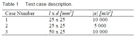
The projectile was decelerated from steady state Mach 1.2 to 0.8 at zero incidence. The unsteady results are then compared to steady state data in the same Mach number range. Case 1 investigates the flow field behaviour for the projectile of identical geometry to the experimental case of Jiang et al. [1], case 2 will demonstrate effects at half the deceleration magnitude and case 3 will consider the effect of increased Aspect Ratio (AR). Static free stream pressure is 101 325 kPa and temperature 297 K. Red ranges from ~ 0.5 x 10⁶ at Mach 0.8 to ~ 0.7 x 10⁶ at Mach 1.2 where density and viscosity are referenced to far-field ambient conditions. The ideal gas law and Sutherland's law are applied. The projectile shape is a solid, cylinder with constant diameter.
A second order, implicit RANS (Reynolds Averaged Navier-Stokes) model with Menter's k-ω SST turbulence model was used with the density-based option. The first cell adjacent to the wall has a y+ ~ 1 which is required for this turbulence model. Roe-FDS (Flux Difference Splitting) was selected for spatial discretization.
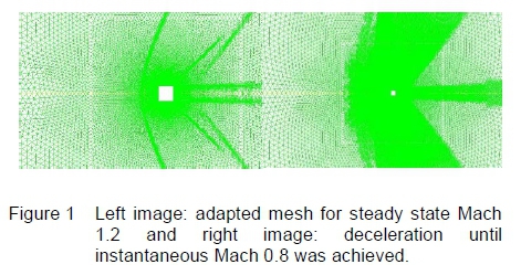
Transient simulations was initialised with the steady state result and had a second order, implicit, transient formulation. A timestep of 1 x 10⁻⁵ s was found adequate with 50 inner iterations to achieve convergence per time-step. Smaller timesteps was found not to sharply resolve the bow shock during deceleration. The two-dimensional, unstructured grid of triangular elements was refined, but not coarsened, based on normalized density gradient at a threshold value of 0.05. The asymptotic behavior in the axial force monitor and mass flux tending to 0 were used as indicators to assess solution convergence for steady state. The typical adapted mesh is shown in figure 1 for steady state and the transient (deceleration) cases. The effect of using refinement only on the mesh during a transient simulation can also be observed in that flow for later Mach numbers has affected the grid.
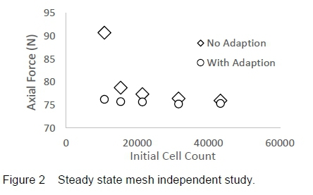
The outcome from a mesh independent study is shown in figure 2 where a difference of ~ 0.5% in axial force exists between the last two successive data points using mesh adaption. The finest grid provides better overall resolution of the near field flow structures in vicinity of the model and is the reason why a coarser grid was not selected although mesh adaption resolves axial force that is relatively converged when compared across the different grid sizes used for the independence study.
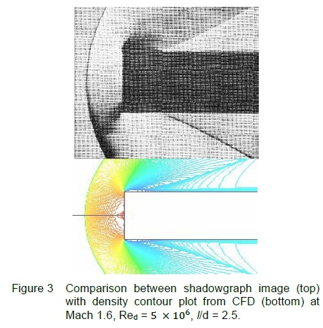
A shadowgraph result [7] is compared with simulation using an equivalent mesh and solver set-up for the cases listed in table 1. The experiment is a steady state plane nosed cylinder at Mach 1.6, Red = 5 x 10⁶ and zero-incidence. The result is shown in figure 3 where good qualitative agreement with the CFD density plot in terms of bow shock stand-off distance, its curvature and the oblique shocks marking the end of the expansion region. This exercise including the mesh independent study gave good confidence in the steady state mesh and solver setup before utilizing the source terms for the deceleration study.
The following information was reported in the experimental study [7], sufficient to establish the required initial boundary conditions for the simulation with an isentropic flow assumption: Reynolds number (Red), Mach (M) number and aspect ratio (AR). The numerical test conditions to replicate the experiment assumed a static temperature of 300 K, projectile diameter 25 mm and a computed static pressure of 57 222.78 Pa. These conditions match experimental Red and M.
3 Results and Discussion
Prior to an analysis on the flow-field, a brief description of pertinent flow features is made based on the steady state case. For subsonic flow, figures 4(a) and 5(a), the projectile's sharp leading vertex induces flow separation creating a shear layer extending downstream into the wake region (A). The shear layer's curvature induces local compression and expansion which is identified by the presence of shocks and expansion regions (B) upon the shear layer surface.
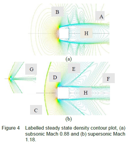
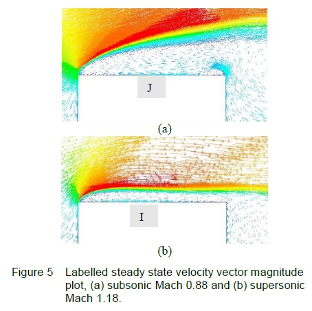
For supersonic flow, figures 4(b) and 5(b), the projectile, being a bluff body, generates a detached bow shock (C) encompassing a subsonic region between this shock and projectile nose. The ensuing shear layer formed by the sharp leading vertex is closer to the cylindrical surface enclosing an elongated, separation bubble that contains recirculating flow (I). For subsonic Mach<1, the recirculation region beneath the shear layer contains multiple vortices (J). Upon the upper surface of the curved shear layer, the flow expands to supersonic Mach>1 and is labelled (D). The typical flow expansion at the leading edge is shown with velocity vectors for greater clarity in figure 5, for both subsonic and supersonic flow.
For an aspect ratio (AR) of 1, the shear layer does not re-attach to the cylindrical surface where re-attachment was noted for AR = 2. The flow expands through the expansion region and is further accelerated due to local shear layer curvature sufficient to cause a terminating shock (E) to form away from the cylindrical surface. This shock is required to re-align the flow emerging from the expansion region. The flow remains detached at the trailing vertex and the shear layer continues downstream into the wake, inducing compression waves (F).
The shear layer curvature in the wake region contributes to formation of the compression waves. These compression waves coalesce into a wake-recovery shock (G) in the far-field to match the downstream post shock flow conditions. A recirculating vortex flow exists in the wake region (H) close to the projectile body. Velocity vectors indicate recirculating flow on the entire cylindrical wall in figure 5(a) and 5(b) with multiple vortex regions.
3.1 Case 1: Discussion for Aspect Ratio = 1
The unsteady flow-field for the decelerating projectile is compared at corresponding steady state Mach numbers in Figures 6 and 7. Selected flow field states were taken between Mach 1.15 and Mach 0.8 for the comparison.
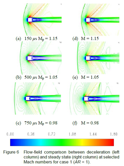
Noticeable differences exist in the flow field for supersonic projectile Mach numbers. This is not apparent from the deceleration drag coefficient plot in figure 10 for Μ ~> 1.1 where the results for steady state and deceleration closely overlap. For aerodynamic bodies at zero-incidence the drag coefficient or axial force is similar at supersonic Mach [3,4], further, flow structures associated with supersonic Mach is important as these can influence the flow-field at later times during deceleration of the object.
From figure 6, the instantaneous flow field for projectile Mach 1.15 is similar to the steady state result, slight differences was identified in the expansion region, bow shock curvature and wake thickness. Since the projectile was decelerated from steady state Mach 1.2, the unsteady flow field in comparison with steady state become more detectable at lower supersonic speeds, for example in figure 6(b), greater definition of the bow shock occurs in the deceleration case.
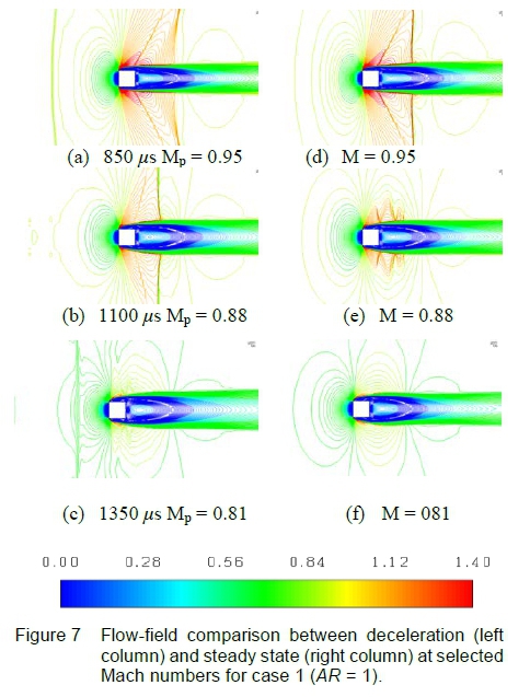
Referring to figure 6(c), the instantaneous projectile Mach number is subsonic. The first observation refers to the bow shock which is present ahead of the projectile and was formed at supersonic speed. No bow shock exists for steady state subsonic Mach 0.98 in figure 6(f). From figure 7(a) and (b), the second observation refers to the lag in development of the compression waves in the outer wake vicinity into a wake recovery shock, when comparing the deceleration case to steady state. These two observations further explain the flow history concept.
In steady state motion, the bow shock and projectile move at equal speeds. Upon projectile deceleration - refer to figures 6(a-c) - the bow shock propagates forward, following its initial path of motion, reducing in curvature and eventually decaying into a compression wave. During this process, the flow field between the bow shock and projectile is nonuniform and unsteady which is different to steady state where this flow field is non-uniform and steady.
Supersonic expansion occurs upon the shear layer emanating from the leading vertex over most of the transonic Mach range where a terminating shock develops at the tail-end of the expansion region, in figure 6(a). During deceleration, the terminating shock curvature changes from convex to concave, relative to the oncoming free-stream.
Simultaneously at the cylinder aft-end, the trailing compression waves rotate forward and translate towards the projectile, this is observed in figure 6(a-c) and figure 7(a-b). These compression waves will later steepen into an oblique shock where the foot of this shock extends to the shear layer, shown in figure 7(a-b). This shock will, at a later time, overtake the projectile and emerge ahead as a series of compression waves travelling at local acoustic speed, shown in figure 7(c). Note that further away from the projectile these compression waves have already coalesced to form an oblique shock - refer to figures 4 and 8.
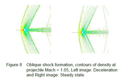
The wake recovery shock in the far-field is shown in figure 8, for instantaneous Mach 1.05. In this figure, the bow shock appears closer to the projectile nose relative to the steady state position. This difference is more pronounced at the lower supersonic Mach numbers and has been observed for decelerating spheres [6]. This is another example of flow history where the bow shock position and curvature associated with Mach 1.05 is representative of steady state at a Mach number greater than 1.05.
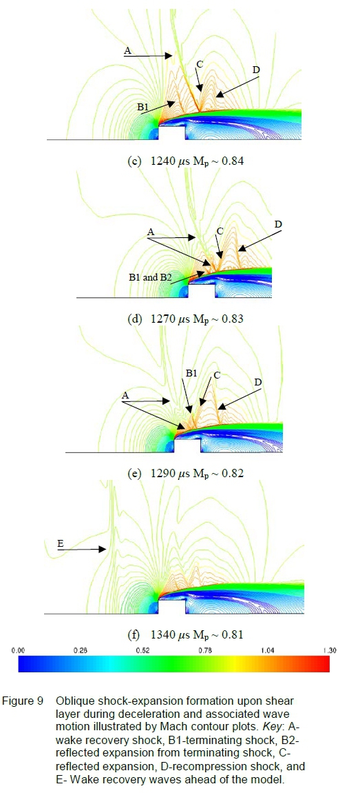
Figure 9 illustrates how the wake recovery shock (labelled as A) propagates upon the shear layer, that behaves like a free boundary, where reflected expansion fans is formed immediately behind the shock caused by the shocks local deflection of the shear layer - labelled as C in figure 9.
Local flow acceleration occurs through these reflected expansion fans that necessitates a re-compression shock, first shown in figure 9(c) to force the flow to match near downstream conditions. The region of expansion between the terminating shock and re-compression shock increases in width while the terminating shock is propagating upon the shear layer. The increased width of the expansion region permits the flow to accelerate locally over a greater distance, causing the re-compression shock to strengthen, this effect is identified through image (c), (d) and (e) of figure 9. At the instantaneous positions shown in figures 9(d) and (e), the wake recovery shock and its associated reflected expansion, propagating upon the shear, overtakes the terminating shock and emerges ahead of the projectile shown in figure 9(f).
The wake recovery shock has been identified to behave as a compression wave ahead of the projectile in Figure 7(e), for instantaneous Mach 0.81 and at later times as an acoustic compression wave. The reflected expansion retains its behavior once having overtaken the projectile and dissipates into an acoustic expansion wave.
Once the wake recovery shock has overtaken the projectile, local supersonic regions formed upon the curved shear layer near the separation point weaken since the projectile is decelerating. Local expansion and re-compression waves are formed above the shear layer that are relatively weak compared to wave structures identified in figure 9. These weak wave structures will eventually overtake the projectile with further deceleration.
3.2 Case 2: Effect of Reduced Deceleration Magnitude
The instantaneous drag coefficient for the AR = 1 projectile is shown in figure 10 and is compared to the steady state drag coefficient. The flow density in the dynamic pressure (  ) term is referenced to undisturbed, ambient conditions for pressure and temperature which is reasonably true for conditions at infinity, however an improved definition may be necessary since the instantaneous subsonic flow field contains flow structures of earlier time; e.g. at subsonic projectile speeds, the bow shock and wake recovery shock propagates forward, ahead of the projectile. These shocks will eventually decay, at different rates, into compression waves and then further into acoustic waves. The impact of these waves on the far field density and whether this will be significant towards the above definition of dynamic pressure requires further study. The velocity (v) for the dynamic pressure is taken as the instantaneous projectile velocity and similarly for the Mach number.
ANSYS Fluent generated force data in the direction of motion for pressure and shear loading over the entire projectile surface. This data revealed pressure loading was dominant. For a projectile at zero incidence, the pressure loading on the cylindrical surface will be equal between upper and lower surfaces relative to the longitudinal axis. This results in their cancellation. Therefore, contributors to drag is primarily pressure difference between the front and rear face of the projectile. The identification of the specific drag components (e.g. base drag, wave drag, form drag) is not in the scope of this investigation.
Bow shock movement and eventual overtaking by the trailing compression waves during deceleration was explained previously and this can affect pressure loading on the forward face of the projectile whereas the pressure loading upon the projectile's rear face can be influenced by changes in the wake thickness, shear layer curvature, and compression wave strength and location. There is strong coupling between the flow mechanisms in the near wake and outer region of the separation bubble that influences the shock dynamics in vicinity of the model. This arose based on the model AR used. Larger AR models (AR>>1) had not exhibited this coupling effect [3].
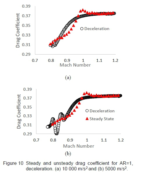
Figure 10(a) shows the unsteady drag coefficient plot where a noticeable difference in Cd occurs during the transonic range around Mach 0.8 to Mach 1.1. The instantaneous drag coefficient varies smoothly through Mach 1 with no peak and continues in this manner down to about Mach ~ 0.8 where perturbations in the flow-field cause a wave-type behaviour affecting the drag coefficient. These perturbations coincide when the wake recovery shock and its reflected expansion wave (described in figure 9) propagates over the projectile. Further investigation is needed on the influence of this wave interaction with the projectile.
The steady state drag coefficient develops a peak at Mach 1 and fluctuates relative to the deceleration case. This was observed for both models (AR=1 and 2), including a similar effect for aerofoils and cone-cylinders [3,4]. A reduced deceleration magnitude of 5 000 m/s2 was selected to emphasize deceleration effects and these were found to be present. The instantaneous and steady state drag coefficient behaviour for this reduced deceleration magnitude is shown in figure 10(b).
There is greater fluctuation in the lower transonic Mach range relative to figure 10(a). A similar trend in the fluctuation at around Mach 0.8 was identified for cone-cylinders [3]. The transonic Mach range (0.9<M<1.2) has similar behaviour to the case of deceleration at 10 000 m/s2.
3.3 Case 3: Effect of Increased Aspect Ratio (AR=2)
The effect of doubling the AR is discussed with reference to figures 11 and 12, where the overall flow-field during deceleration lags in development compared to the steady state result, with exception to flow features that are unique to the deceleration case.
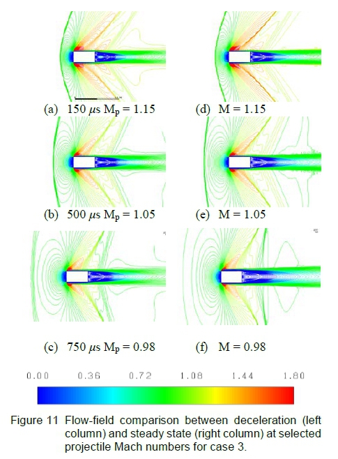
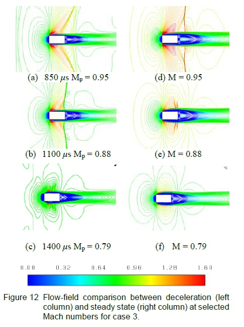
The key flow-field differences could be attributed to shear layer behaviour whose local curvature in the vicinity of the projectile surface and near wake is different from case 1 for AR = 1. The overall steady state flow-field is similar to that illustrated in figures 4(a-b).
These compression waves aft of the projectile body propagate towards the leading edge during deceleration and interact with the expansion region caused by the curvature of the leading edge shear layer. This interaction initially results in a lambda formation near the shear layer upper surface in figure 12(b) and disappears as the projectile continues decelerating.
The compression waves in the wake region, shown in figure 12(a-b), will propagate forward and interact with the terminating shock and merge into a single wave, unlike the case for AR=1 where these two waves remain distinct. This combined wave will be referred to as a modified-terminating shock since this shockwave returns supersonic expansion flow to subsonic speed.
The modified-terminating shocks location upon the shear layer moves towards the leading edge and reduces in height, shown in figures 13(b) and (c), where creating reflected expansion fans (labelled B) are formed in the downstream direction. A re-compression shock develops due to local flow acceleration shown in figure 13(c). This figure also shows presence of compression waves (labelled G) ahead of the projectile.
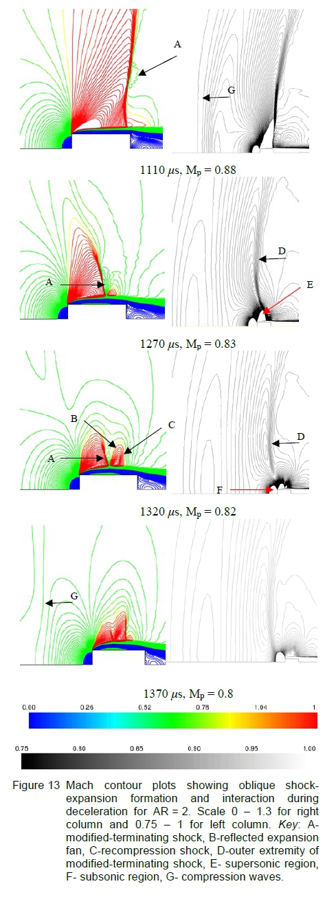
The right column of figure 13 illustrates the process on how the compression waves form ahead of the projectile and corresponds to the image shown on the left column in terms of Mp. These images have a Mach number contour range of 0.75 to 1 which was found to enhance the presence of far-field structures. For completeness, supersonic and sub sonic regions are labelled E and F respectively in figure 13, corresponding to the blanked out regions based on the narrower Mach number range.
The modified-terminating shock extends outward into the far-field (labelled D in figure 13) and is a relatively weak structure compared to the strong wave system present near the shear layer.
This wave was observed to continue propagating forward while its lower portion (labelled A in figure 13) remained with the shear layer. This is expected based on the fluid inertia concept where the wave has a tendency to continue propagating along its initial motion path during deceleration. Great differences in fluid velocity near the supersonic expansion region compared to further outward in the far-field can influence relative wave speed for the modified-terminating shock causing the wave's portion near the model to propagate at a slower speed. Figure 13(b) right column shows the outer portion of the modified-terminating shock in contact with the supersonic expansion region whereas at a later instance figure 13(c) right column, this wave has propagated away from the supersonic region. The compression waves present ahead of the projectile for AR=2 is the outer extremity of the modified-terminating shock.
The relative spacing between the compression waves ahead of the projectile is greater than in case 1 for AR=1 which is shown in figure 9(f). This infers that the modified-terminating shock has a weaker compression effect once having overtaken the projectile for an AR of 2. This weaker behaviour of the compression waves can be expected as the projectile with an AR of 2 has a greater length compared to the AR =1 case. Other flow effects in the vicinity of the separation bubble could contribute to the weaker compression wave formed ahead of the model for AR=2, where further study is required on this interaction.
From figure 12 for unsteady, subsonic projectile Mach numbers, the low pressure region in the wake appears closer to the projectile rear surface when compared to the corresponding steady state case. This could create a low-pressure suction-effect upon the shear layer causing increased local curvature in the vicinity of the projectile's trailing edge.
This curvature may contribute to the local flow acceleration and the need for the re-compression shock upon the shear layer identified in figure 13. The supersonic expansion region on the outer surface of the shear layer, further contributes to its elongation in the radial direction. Since the shear layer appears attached for subsonic and supersonic projectile Mach numbers in figures 11 and 12 respectively, it is unlikely that mass entrainment occurs between the near recirculating wake region and the aft end of the separation bubble on the cylindrical surface.
4 Conclusions
The flow field around a decelerating blunt projectile at zero incidence was investigated for the transonic Mach number range. This paper briefly includes the effects of aspect ratio and deceleration magnitude. This exercise confirms that a more detailed and direct study on either effect is worthwhile and to investigate alternate geometries.
The deceleration magnitude for case 1 was selected based on the work of Jiang et al. [1]. Plots of drag coefficient against Mach number illustrate clear differences between deceleration and steady state results, with similar trends to cone-cylinders [3]. The usage of the dynamic pressure term for the unsteady drag coefficient was explained.
The detached bow shock was found to behave in a similar manner compared to previous studies on decelerating spheres, cone-cylinders (restricted to conical nose sections of AR ~ 1), and aerofoils. The bow shock curvature at any instantaneous supersonic Mach number has greater curvature and leans closer towards the projectile body than a steady state result at the corresponding Mach number. Simultaneously, the bow shock moves ahead of the projectile nose and remains present in the upstream flow-field during subsonic projectile speeds where the bow shock reduces in curvature until the wave is approximately perpendicular to the flow. During propagation and reduction in curvature, the bow shock transitions to finite compression waves then further into acoustic waves.
The compression waves in the wake region were found to move forward, against the flow, and coalesce into a wake recovery shock that overtakes the projectile, for projectile Mach < 1. The flow expansion due to shear layer curvature from the leading edge is of sufficient strength to cause formation of a terminating shock. Closer inspection during the overtaking process indicated that the wake recovery shock passes through and overtakes the terminating shock. Once ahead of the projectile the wake-recovery shock behaves as a compression wave which progressively weakens towards an acoustic wave. The reflected expansions from both shocks, i.e. the wake recovery shock and terminating shock, have sufficient strength to impart a downward local deflection of the shear layer. The modified shear layer curvature (in the vicinity of this deflection) induces the reflected expansion fans.
The projectile aspect ratios selected for this study, demonstrate coupling between the wake region and the flow in the vicinity of the separation bubble. In particular, the wake recovery compression waves collide with the terminating shock and the expansion region caused by the shear layer curvature. This interaction was not apparent in studies with AR >> 1 and could possibly exist for very low AR cases only. Doubling the aspect ratio altered the wave interactions where the wake-recovery and terminating shocks merge and for this discussion was termed a modified-terminating shock. The outer extremity of this wave was found to propagate faster and eventually over take the projectile.
The effect of deceleration was briefly investigated by halving the initial value from 10 000 m/s2 to 5 000 m/s2. The drag coefficient plot is similar in trend for both magnitudes, except a greater sensitivity in the lower transonic Mach range for 5 000 m/s2.
Analysis on the flow mechanisms around a projectile subject to significant deceleration permits an improved understanding on the unsteady, compressible effects that arise and changes in behaviour of the fundamental flow physics.
Acknowledgement
The financial assistance of the National Research Foundation (NRF) towards this research is hereby acknowledged. Opinions expressed and conclusions arrived at, are those of the author and are not necessarily to be attributed to the NRF. The Council for Scientific and Industrial Research (CSIR) as the host institution and the supervision through the University of Witwatersrand, Flow Research Unit, is gratefully acknowledged.
References
[1] Z. L. Jiang, K. Takayama, and B. W. Skews. Numerical study on blast flowfield induced by supersonic projectiles discharged from shock tubes. Physics of Fluids, 10(1):277-288, 1998. [ Links ]
[2] I. M. A. Gledhill, K. Forsberg, P. Eliasson, J. Baloyi, and J. Nordström. Investigation of acceleration effects on missile aerodynamics using computational fluid dynamics. Aerospace Science and Technology, 13(4-5): 197-203, 2009. [ Links ]
[3] I. Mahomed, H. Roohani, B.W. Skews, and I. M. A. Gledhill. Flow-field for an accelerating axisymmetric body. In 31st International Symposium on Shock Waves Conference, Nagoya, Japan, 17-20 July 2017, (Proceedings in Press).
[4] H. Roohani and B. W. Skews. The influence of acceleration and deceleration on shock wave movement on and around aerofoils in transonic flight. Shock Waves, 19(4):297-305, 2009. [ Links ]
[5] T. Saito, K. Hatanaka, H. Yamashita, T. Ogawa, S. Obayashi, and K. Takayama. Shock stand-off distance of a solid sphere decelerating in transonic velocity range. Shock Waves, 21(5):483-489, 2011. [ Links ]
[6] H. Roohani, I. M. A. Gledhill, and B. W. Skews. CFD models of shocks and flow fields associated with decelerating spheres in terms of flow history and inertial effects. In 31st International Symposium on Shock Waves Conference, Nagoya, Japan, 17-20 July 2017, (Proceedings in Press).
[7] A. Stanbrook. A Correlation of the Forebody Drag of Cylinders with Plane and Hemispherical Noses of Mach Numbers from Zero to 2.5. Ministry of Aviation Report, Aeronautical Research Council, 1964.
[8] T. Kikuchi, K. Takayama, D. Igra,, and J. Falcovitz. Shock standoff distance over spheres in unsteady flows. In Proceedings of the 30th International Symposium on Shock Waves Conference, Vol. 1, pages 275-278, Tel Aviv, Israel, 19-24 July 2015.
[9] J. Allen and M. Ghoreyshi. Forced motions design for aerodynamic identification and modelling of a generic missile configuration. Aerospace Science and Technology, 77:742-754, 2018. [10]G. [ Links ]
[10] Kumaravel, P. Jeyajothiraj, and E. Rathakrishnan. Transonic shock wave patterns over an airfoil in an accelerated flow. International Review of Aerospace Engineering, 8(2):56-70, 2015. [ Links ]
Received 15 December 2017
revised form 9 May 2018
accepted 13 July 2018

