


Services on Demand
Article
 English (pdf)
 Article in xml format
 Article references
Indicators

Related links
-
 Cited by Google
 -
 Similars in Google
Share

 Permalink
R&D Journal
On-line version ISSN 2309-8988
Print version ISSN 0257-9669
R&D j. (Matieland, Online) vol.33 Stellenbosch, Cape Town 2017
Development and testing of a scale model Clamshell mucker
ST MossI; TJ FrangakisII
IUniversity of Witwatersrand. Now Murray & Roberts Cementation (Pty) Ltd, Private Bag 3010, Bedfordview, 2008, South Africa. E-mail: steven.moss@murrob.com
IIMSAIMechE. School of Mechanical, Industrial and Aeronautical Engineering, University of the Witwatersrand, Private Bag 3, WITS, 2050, South Africa. E-mail: terrance.frangakis@wits.ac.za
ABSTRACT
The aim of the research was to develop a scaled experimental model of a Clamshell mucker and assess its performance over a range of operating parameters, including bucket closure angular velocity, bucket starting height (translating into increased depth of penetration and bucket fill), bucket angle of attack, and location of the bucket relative to a boundary wall. An experimental rig was developed consisting of a 1/6th scale model opposed bucket arrangement which was actuated by means of hydraulic cylinders. The digging performance was assessed in two materials: a mixture of hard plastic spheres (of diameters 19 and 25 mm), and 13 mm decomposed granite stone aggregate. Flow visualisation tests conducted in the plastic spheres and stone aggregate revealed that particles move initially downwards ahead of the bucket jaws before rising to the interior of the buckets. Tests conducted in decomposed granite revealed that force chains developed between the particles which resisted the motion of the buckets. The force chains resulted in local peaks in the bucket torques. The peak torque required to scoop material was found to increase with increasing depth ofpenetration, was not affected significantly by angular velocity of the buckets (although the number of local peaks associated with force chains decreased), bucket torque was found to increase in the presence of a smooth boundary within one particle width of the buckets, and was not significantly affected by different angles of penetration. An initial estimate of the energy required to fill the buckets indicated that the least amount of energy was required for lower bucket angular velocities. However, at low angular velocities there was a propensity for bucket stall due to the wedging of particles.
Additional keywords: Shaft sinking, Cryderman loader, mucking, lashing
Nomenclature Roman
Acyi hydraulic cylinder cross sectional area [m2]
Fcyi hydraulic cylinder force [N]
Ffriction fricitonal force resisting motion of the pin [N]
Fiink bucket link axial force [N]
Fsiotpin reaction due to slot surface [N]
K distance from bucket hinge point to initial position of the pin attached to the cylinder and links [mm]
L length of link [mm]
M distance from bucket hinge point to link attachment point [mm]
N moment arm for the bucket link [mm]
P horizontal offset of cylinder attachment relative to bucket hinge [mm]
Pcyihydraulic cylinder pressure [Pa]
Q vertical offset of cylinder attachment relative to bucket hinge [mm]
R cylinder closed centre length between attachment pins [mm]
T total reactive torque experienced by buckets due to resistance of material [Nm]
xcyi actuating cylinder stroke [mm]
Xpin link pin displacement [mm]
Greek
α angular displacement of bucket [degrees]
αinitial initial angular displacement of bucket [39 degrees]
αfinal final angular displacement of bucket [110 degrees]
β angular displacement of actuating cylinder [degrees]
θ angular displacement of link [degrees]
μ coefficient of sliding friction [-]
1 Introduction
Shaft sinking is a critical activity in the establishment of a new mine or accessing deeper orebodies in existing mines. It involves the cyclic activities of drilling, blasting, cleaning (also known as 'mucking' or 'lashing'), hoisting of blasted material in buckets ('kibbles'), blow-over (collection of fines using compressed air), support drilling, concrete lining, shaft equipping, station construction etc. where these functions are usually conducted from a suspended platform ('shaft-sinking stage')1. The process of sinking a shaft that may be as deep as 2500 m or more, and may be as wide as 8 m diameter or more, is time consuming and may last more than two years, with sinking cycles lasting as much as 30 hours per cycle2.
Of all of the cyclic operations in shaft sinking, lashing and hoisting of blasted material (which are interdependent functions) occupy a significant portion of the cycle time3. These functions involve the loading of blasted material into kibbles which are hoisted to the surface and discharged. In the early stages of sinking, when the shaft is shallow, the hoisting times are low. However, as the depth of the shaft increases, the hoisting time also increases. Initially, at shallow shaft depths, the time taken to fill a kibble is longer than the time taken for an empty kibble to be returned to the shaft bottom for refilling (i.e. the lashing process is the limiting factor). However, as the shaft deepens, a depth is reached where hoisting becomes the limiting factor. Simulations carried out on different shaft diameters and loading techniques4 showed that the theoretical critical depth for a two kibble configuration (one detached kibble being loaded at the shaft bottom while another is being raised-discharged-lowered) was 780 m. By contrast, a three kibble configuration (one kibble at the shaft bottom, one being raised and another simultaneously being lowered) had a theoretical critical depth of 2670 m. Since most shafts that are sunk are not deeper than this theoretical depth, and since most sinking operations make use of three kibbles, it is likely that lashing is the constraint in the sinking cycle.
The processes of lashing and hoisting are dependent on many factors including, amongst others, shaft diameter, blast-hole depth, type of lashing system used to load the kibbles, size and number of kibbles used, fragmentation of the rock etc. Modern day lashing for particular shaft sinking operations have been reported to occupy between 32 - 41% of the cycle times2,3, while historic data5 shows that it occupied as much as 67% of the cycle time. In addition to the time taken to lash the blasted material, lashing is also a hazardous activity as it involves the scooping and dumping of many tonnes of material into kibbles, raising and lowering of kibbles etc., which all take place in a confined area at the shaft bottom where workers are located. In addition to the mechanical hazards there are also safety issues associated with noise, presence of ground water at the shaft bottom, uncontrolled motion of rope suspended lashing grabs (if this type of system is used), fractured rocks dislodging from shaft sidewalls and falling into the work area at the shaft bottom, the ability to communicate effectively, and others.
The efficiency and safety of the lashing process are therefore critical factors to consider in the shaft sinking cycle, and also represent two areas where significant advances may be made.
2 Literature Review
Prior to the 1930's lashing was done manually with workers at the shaft bottom using shovels to place blasted material ('muck') into the kibbles. In 1938 the EIMCO Rocker Shovel Loader 12B was introduced6 which improved loading rates significantly. This evolved into the Model 630 Loader which was a crawler or tracked version of the 12B Loader. It had a bucket located at the front and a mechanism that could raise and discharge the bucket into a kibble located behind the machine in an over-throw motion (hence it is often referred to as an 'overshot loader' or an 'over-throw' loader).
In the 1940's clamshell bucket loaders began to be developed7. These loaders consisted of two opposed buckets which were suspended from an elevated platform. When actuated, the buckets enclosed a volume of material between them, rather than relying on the resistance of the material to force it into the bucket, as was the case with the single bucket of the 630 Loader. Two clamshell-type devices were developed and used extensively: the Riddell mucker and the Cryderman mucker7. The main difference between them was that the Riddell mucker clamshell buckets were suspended on ropes while the Cryderman mucker clamshell buckets were attached to the end of a telescoping boom.
In the 1950's the Cactus Grab was introduced and was used to sink the No. 2 shaft at the Vlakfontein mine in South Africa7. It was successful and became a popular choice for shaft cleaning due to its high loading rate. The grab consisted of a grapple with 6 or 8 claws ('tines') which were activated by a large pneumatic cylinder. The grab was also suspended from a rope hoist system. It is still popular today.
The Cactus Grab and Cryderman loaders will be reviewed in more detail below, highlighting their particular strengths and weaknesses. The EIMCO 630 Loader and the Riddell clamshell mucking system will not be examined as they have significant disadvantages. These relate primarily to safety of operations, suitability to particular shaft configurations, rock fragmentation constraints and surface of the blasted and solid materials. As a result they are not commonly used any longer.
2.1 Cactus Grab
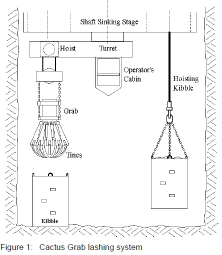
The Cactus Grab consists of a grab which is suspended from cables that are attached to a hoist. The hoist is attached to a cantilevered arm which is pivoted centrally on the underside of the shaft sinking stage such that the arm can sweep through 360 degrees. The hoist can move radially along the arm such that grab can cover all areas of the shaft bottom8. The loading action is as follows. The tines of the grab are opened and the grab is lowered under the action of gravity into the blasted rock or 'muck' pile. Thereafter the tines are actuated by a pneumatic cylinder so that they close and entrain a volume of muck between them. The grab is then raised, positioned over a kibble and the tines opened so that the muck is discharged into the kibble. A schematic of the Cactus Grab lashing unit is shown in figure 1.
The Cactus Grab system has a mass of 10 tonnes9. The grab itself has a capacity10 of 0.56 - 0.85 m3. Loading rates vary widely and are reported3,10 in the range of 100 - 250 tonnes/h. However, data from the sinking of an 8.1 m diameter shaft2 indicated that the average loading rate was about 50 tonnes/h (averaged over 152 cycles with an advance of 3 m per cycle). In reality, instantaneous rates could be two or three times higher, which is substantially lower than the maximum instantaneous rates quoted.
The operator of the grab is located above the unit in a cabin, which affords good visibility10. The Cactus Grab is reported to be particularly suited to large diameter shafts (typically of the order of 8 m or more)11. In smaller diameter shafts operating space becomes problematic and loading rates are reduced (particularly if two kibbles are present at the shaft bottom during the lashing phase).
Advantages
1. The Cactus Grab has the highest instantaneous loading rate of the various lashing systems used commercially.
2. It may operate reasonably independently of the position of the stage since the grab is mounted on ropes.
3. The turret system ensures that all parts of the shaft bottom may be reached by the grab.
4. The selection of kibble geometry is not constrained (as compared with the 630 Loader where the rim height of the kibble cannot exceed the height at which the bucket discharges the material into the kibble).
5. Large rock fragments are handled relatively easily by the grab.
Disadvantages
1. The grab is heavy, which adds a significant mass to the stage, which increases the stage hoist rope diameters, cost of the stage etc.
2. While the instantaneous loading rates are high, the average loading rates are considerably lower because the grab tines become ineffective when the layer of blasted material becomes shallow and the remaining material needs to be hand lashed.
3. The grab is not able to clean effectively against the shaft sidewalls due to the near hemispherical shape of tines when they are closed. This necessitates further hand lashing of rock. The grab also struggles to clean highly fragmented material (fines).
4. The grab relies on gravity to penetrate the muck pile. This is inefficient particularly near the end of the lashing cycle when the layer of muck is shallow.
5. Safety is a concern when using the Cactus Grab. This is due to use of hoist ropes as slack rope may lead to fouling and damage of the ropes (with costly maintenance and downtime), there may be uncontrolled swaying of the grab during loading of the kibble and also uncontrolled motion during penetration of the muck pile. Safety may also be an issue as communication between the operator and a worker located at the shaft bottom is limited.
6. The grab, hoist and arm from which it is suspended are attached to the underside of the stage and therefore occupy a significant amount of space. This limits the distance that the stage may be lowered so that when lining the shaft with concrete the lining may not come as close to the shaft bottom as may be desirable. It also leads to more difficult maintenance of the unit.
2.2 Cryderman Loader
The Cryderman Loader has two opposed buckets which are mounted on a telescoping boom, which itself is attached to a support frame. This support frame is either mounted on the underside of the shaft sinking stage or is guided within the stage so that it can move up and down relative to the stage12. The buckets and the telescoping boom are actuated either pneumatically or hydraulically10. The angular position of the boom is also controlled by cylinders. This is shown in figure 2.
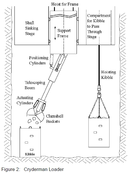
Material is scooped into the buckets as follows. The buckets are first opened fully. The telescoping arm extends so that the buckets penetrate the muck. The buckets are then closed, capturing a volume of muck in their combined interior. The boom is retracted and the buckets positioned over a kibble for discharge. While the digging actions of the Cryderman Loader and the Cactus Grab are similar, they differ significantly in that the telescoping arm provides a positive penetration of the muck pile (without the aid of gravity, and without the use of ropes). Therefore, the positioning of the arm and the action of digging into the muck are controlled motions, resulting in increased safety at the shaft bottom.
Cryderman Loaders are reportedly suitable for smaller shaft diameters (5.5 m or less), but, for larger shaft diameters would need to work in pairs to cover the extents of the shaft bottom10. The loading rates are reported to be between 50 -73 tonnes/h per machine10.
A modern version13,14 of the Cryderman Loader has a bucket capacity of 0.57 m3 and a telescoping arm with a stroke of 4.3 m.
Advantages
1. The opposed clamshell buckets do not rely on resistance of the muck pile to entrain material into the buckets (as is the case with the 630 Loader). This is beneficial when the muck pile becomes shallow, towards the end of the cleaning cycle.
2. The telescoping arm provides a positive motion for the buckets to penetrate into the muck pile, rather than relying on gravity.
3. The buckets are able to lash smaller rock fragments, are able to lash more effectively against the shaft sidewall, and are effective even when the layer of blasted rock becomes shallow.
4. Safety in the working area is improved due to the positive control of the boom. Since the buckets are not suspended on ropes there is no chance of rope slack leading to a dangerous situation for workers at the shaft bottom, which could become entangled with kibbles, or the potential of swaying or uncontrolled motion of the buckets.
Disadvantages
1. Large rocks would be more difficult to handle than with the Cactus Grab. Larger rock fragments caught between the jaws of the buckets may prevent complete closure of the buckets and lead to smaller particles escaping from the buckets.
2. The loading rate of the Cryderman Loader is less than that of the Cactus Grab. Depending on the shaft sinking system layout this could be addressed by adding a second unit, which would also add a measure of redundancy.
3. Due to the limited stroke of the telescopic arm, the stage position relative to the shaft bottom requires adjustment when using the Cryderman Loader. The positioning of the kibbles relative to the telescopic boom is also a constraint as the degrees of freedom and ranges of motion of the components in the system are limited.
3 Research into Digging Behaviour of a Clamshell Mucker
A Masters Research project1 was conducted at the University of the Witwatersrand into the digging behaviour of a scale model Clamshell Mucker.
3.1 Objectives of the research project
The objectives of the research project pertinent to this paper were to:
(i) develop a scale model experimental Clamshell Mucker (based on the Cryderman Loader),
(ii) conduct digging tests in plastic spheres and stone particles for visualisation of particle motion,
(iii) conduct instrumented digging tests in decomposed granite particles using a variety of test variables and measure the required bucket torques to perform the digging operations. The test variables included:
a. the initial bucket distance from the particles,
b. angular velocities of the buckets,
c. angles of attack of the buckets,
d. digging in proximity to confining wall boundaries.
3.2 Scale model test facility
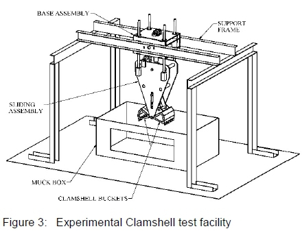
A 1/6th scale model of a Clamshell Mucker (shown in figure 3) was designed and built. The choice of a 1/6th scale was predominantly based on cost (relating to equipment, hydraulics and power pack), the cylinder diameter (and therefore the maximum digging force), and available material particle size.
Scaling in granular materials systems is known to be problematic15, particularly when extrapolating results from scale model experiments to full size systems. However research published on the scaling properties of granular materials16 indicates that geometric lengths and an elastic constant associated with particle interactions may be scaled linearly by a scaling factor, while a dissipative constant and time (for rate dependent experiments) must be scaled non-linearly by a factor of the square-root of the scaling factor.
For the scale model Clamshell Mucker experiment decomposed granite aggregate with a top size of 13 mm was used as it was readily available and would represent fragmentation of about 80 mm size in the full scale application. According to Britton and Lineberry17 fragmentation should ideally be limited to a maximum particle size of 125 mm for all types of mechanical loading. Those authors stated that generally 70 - 80 % of the fragmentation produced by a blast was fine material due to accuracy of the drilling of the blast holes, type of explosives used, and other factors. It was therefore felt that it was not unreasonable to use a particle size of about two thirds of the ideal fragment size.
For the scale model test it was not possible to determine the Young's modulus and Poisson's ratio of the material so published values were assumed. It was also not possible to scale these properties appropriately by selecting an alternative material for the scale model tests. However, it was felt that reasonable insights could be gained by using this material and the effects of having larger elastic and dissipative constants for the scale model could be reasoned.
The scale model test rig consisted of a fixed support frame, a base assembly, a sliding assembly, two opposed clamshell buckets attached to the bottom of the sliding assembly, and a rectangular material container (muck box). The base was pivoted about a horizontal axis such that it could be manually adjusted to angles of attack ranging from zero to 30 degrees to the vertical. The sliding assembly was connected to the base by means of four linear rod/bearing sets and a hydraulic cylinder, allowing for 200 mm displacement relative to the base.
Two opposed clamshell buckets (with a total enclosed volume of 6.50 dm3) were attached to the bottom of the slider assembly and hinged about a common pin. The buckets were modelled on the Cryderman Mucker, with concave sides (subtending an angle of about 50 degrees) and parallel front and rear faces. The height of the bucket opening was 150 mm (or about 11 particle diameters), while its width was 240 mm.
The front faces of the two buckets had polycarbonate windows for visualisation of the particle motion during digging. Due to geometric constraints the buckets did not contain any openings at the top for spill-over of excess material.
The opening and closing motion of the buckets was controlled by links which were attached to a single transverse pin sliding in a slot in the sliding assembly. The motion of the pin was controlled by a second hydraulic cylinder mounted within the sliding assembly. A hydraulic power-pack was used to power the cylinder and could be controlled to provide a constant bucket angular velocity. The connection of the bucket links to a single sliding pin resulted in identical motions of the buckets. The torques required to actuate the buckets were thus averaged, even if different resistances were experienced by the two buckets.
The muck box housing the test material had dimensions of 1300 mm length x 760 mm width x 500 mm depth. It could be moved relative to the buckets in order to test the effect of bucket proximity to smooth sidewalls. It also contained a polycarbonate window for particle visualisation.
Instrumentation included pressure transmitters connected to the two hydraulic cylinders, an angular potentiometer to measure the angular displacement of the buckets and a linear potentiometer to measure the vertical displacement of the buckets relative to a datum (the surface of the test material).
A mechanism analysis was used to determine the following:
1. The relationship between the measured angular displacement of the buckets, the stroke of the pin to which the links were connected and the stroke of the actuating cylinder.
2. The relationship between the measured actuating cylinder pressure, the side force experienced on the link pin against the sides of the slot, the resistive frictional force acting on the pin sliding in the slot, the force generated in the links and the bucket torque. The bucket torque was a measure of the resistance of the test material to bucket penetration during the digging action.
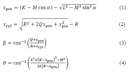
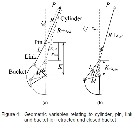
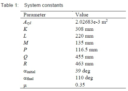
Equations 1 - 4 were derived with reference to figure 4. These relate the positions and angles of system components with respect to geometric parameters, and the angular displacement a of the bucket shown in the figure. The values of the system constants used in the analysis are given in table 1 and the explanations of the parameters in the Nomenclature.
For the purpose of deriving equations for the force in the links, and the reactive torque on the buckets (due to penetration of the material) the following assumptions were made:
1. The reactive torques applied to both buckets were assumed to be equal in magnitude (and hence the forces in the links were also equal). This assumption was made on the basis that even if material was initially scooped unevenly into the two buckets it would tend to move in the direction of least resistance in the bucket interior and rapidly even out the reactive forces acting on the buckets. This would result in similar average torques.
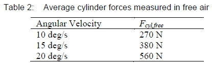
2. The weights of the buckets (mass approximately 5 kg each) and other smaller components such as pins and links, as well as seal friction in the cylinders, were all accounted for as a net average cylinder force required to close the buckets in free air. Measured cylinder forces were offset by these average forces, and thus the weight and cylinder friction terms were ignored in the analysis.
3. The weight of the plastic spheres or stone particles was ignored as it was less than 100 N.
With reference to figures 4(b) and 5, and the assumptions listed above, equations 5 - 10 were derived.
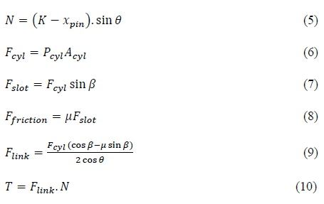
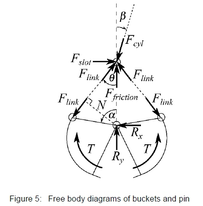
In addition to the geometric relationships determined in equations 1 - 4, equations 5 - 10 enabled a bucket torque to be determined on the basis of the cylinder force Fcyi (which was a function of the measured cylinder pressure, Pcyi, and the cross-sectional area of the cylinder, Acyi) and the geometric relationships of the mechanism components. Since the bucket torque determined was for one bucket, when the energy required to dig a volume of material was determined the torque-bucket angle relationship was integrated and doubled to account for both buckets.
3.3 Experimental results
3.3.1 Test materials
Two types of materials were tested: hard plastic spheres and 13 mm decomposed granite stone particles. The purpose of testing the plastic spheres was to gain broad insights into the interaction between the buckets and spheres, and subsequent motion of the spheres. Two sizes of particles were used: 19 mm diameter spheres (approximately 1/3 of the volume) and 25 mm diameter spheres (remaining 2/3 of the volume). These sizes and quantities were used on the basis of availability.
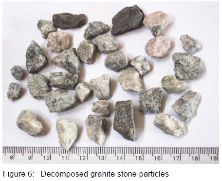
The second material that was tested was typical granite stone aggregate that is used in concrete, with a particle size of -13 mm +5 mm (i.e. would pass through a sieve with apertures of size 13 mm but would not pass through a sieve with apertures of size 5 mm). The particles were highly angular, had a wide size distribution, and had rough surfaces. A few typical samples are shown in figure 6, along with a scale in millimetres.
3.3.2 Motion of particles
Digging tests were filmed using a video camera to capture the motion of particles in order to understand the interaction between the buckets and the particles. The use of a video camera was justified on the basis of simplicity since the motion of the particles was relatively slow and snapshots at particular time instants were sufficient to determine particle motions.
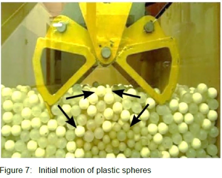
Two series of tests were conducted in the plastic spheres where the initial position of the fully opened buckets was located 30 mm above the spheres, and with the fully opened buckets in contact with the spheres. Both test series were conducted at a bucket angular velocity of 20 deg/s, and where the buckets were located adjacent to the polycarbonate window, in order to facilitate visualisation.
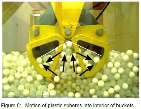
Figure 7 shows the initial digging motion, and the direction of motion of the particles during this stage of digging (as determined from video analysis). The particles immediately ahead of the jaws moved in the direction of motion of the buckets, while surface particles tend to move towards the mid-plane between the buckets. As the bucket motion continued, the spheres immediately in front of the buckets encountered resistance and begin to move upwards, expanding vertically into the interior of the buckets and sliding tangentially along the bucket surfaces into the bucket interior (see figure 8). As the height of the particles in the bucket interior continued to increase, the particles began to spill over and cascade into the bucket interior. The resulting angle of material in the buckets was fairly shallow (shown as a white line in figure 8) as rolling resistance was low.
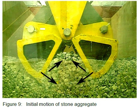
The experiment was repeated with 13 mm decomposed granite stone aggregate and similar results were seen in that particles were initially forced downwards ahead of the bucket jaws before moving upwards in the mid-plane region between the buckets, and sliding tangentially along the sides of the buckets. This is shown in figures 9 - 11.
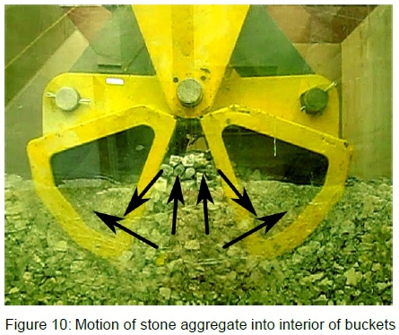
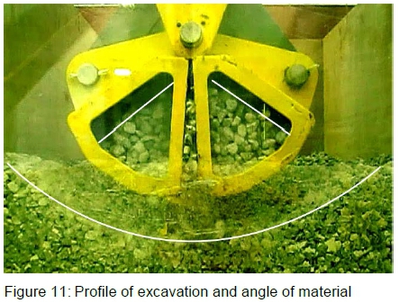
The main differences between the plastic spheres and the granite particles were that: the motion of the particles was more restricted due to interlocking, the angle of stone particles in the interior of the bucket was steeper due to surface roughness of the particles and associated frictional effects (see figure 11), the prevalence of stone particles cascading over one another into the interior of the buckets was less due to surface roughness and particle interlocking, the stone particles wedged themselves between the bucket jaws preventing full closure of the buckets, and a shallow depression was left in the muck pile after the buckets were withdrawn (see figure 11).
These experiments revealed that, with this type of bucket configuration (which does not have any holes at the top of the buckets to allow for excess material to spill out) it was possible to scoop too much material if the bucket starting position was in contact with the muck pile. In such cases the particles began to be compressed and the bucket jaws could not close properly. However, when the starting position of the buckets was 30 mm above the surface of the particles (as in figures 7 - 11), the buckets were not completely filled upon closing. Despite this finding, bucket starting position was retained as one of the test variables, but the upper limit was set to 20 mm above the muck pile which was the starting position which resulted in complete filling of the buckets.
3.3.3 Results of experiments in decomposed granite
Experiments for the 13 mm decomposed granite stone were conducted with combinations of various test parameters which included the starting distance of the buckets from the surface of the material, position of buckets relative to boundaries, bucket angular velocity, and bucket angle of attack. The values of the test parameters are given in the list below.
Test parameters:
1. Starting height: 0, 10, 20 mm (or roughly 0, 0.75 and 1.5 particle diameters)
2. Angular velocity: 10, 15, 20 deg/s.
3. Bucket location: Centre, front, lateral
4. Angle of attack: 0, 5, 15, 30 deg.
At each starting height the clamshell buckets were operated at the three different locations (adjacent to the front polycarbonate boundary, adjacent to the lateral steel boundary and in the centre of the muck box where no boundary effects were present), and at three different bucket angular velocities (10, 15 and 20 deg/s). These tests were carried out with the slider assembly oriented vertically (i.e. 0 degree angle of attack). A minimum of 5 tests per configuration were conducted for repeatability.
Thereafter, three additional angles of attack of the bucket assembly (5 degrees, 15 degrees and 30 degrees) were explored at a constant angular velocity of 20 deg/s, with the buckets positioned in the centre of the muck box.
The forces required to operate the bucket actuating cylinder in free air were determined for various test parameter configurations. These results were used to offset the results during digging tests so as that the effect of the weight of buckets and the cylinder friction could be accounted for in later data analysis. These measured cylinder forces in free air are given in table 2.
The force in a link was determined from the force acting on the slotted pin, and this data was used to determine the reactive torque exerted on the buckets due to the penetration of the muck pile. This reactive torque during bucket closure was attributed solely to the resistance of the material, until the point where the buckets were either fully closed or they were completely filled and began to compress the material, at which point the cylinder pressure increased towards the relief pressure setting (6 MPa). This relief pressure condition was excluded from the data.
Only one test data set, which was deemed to show average response, will be presented in the results. Figures 12 - 14 show the variation of bucket torque at constant bucket positions relative to the muck pile, but varying bucket angular velocities. Figure 12 is for the case where the buckets were touching the muck at the start of the test, while figures 13 and 14 are for the cases where the buckets were 10 and 20 mm above the muck respectively, when the tests commenced.
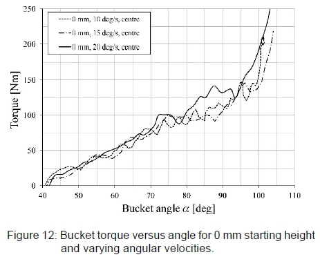
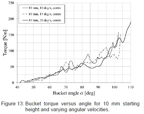
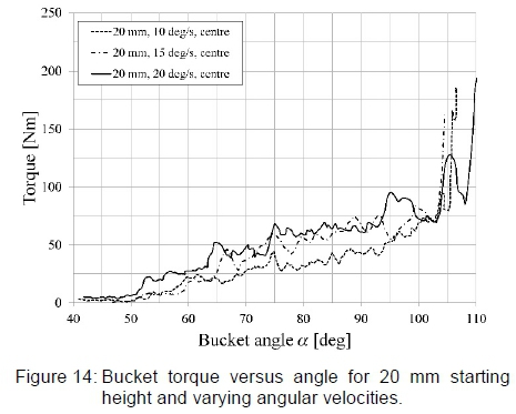
Figure 15 shows the variation of bucket torque as a function of the location of the buckets relative to the forward and lateral boundary of the muck box, as compared with digging in the centre of the muck box. The forward boundary was parallel to the flat sides of the buckets, located at a distance of approximately 12 - 15 mm (or roughly one particle diameter). The lateral boundary test was conducted with the curved outside of the bucket initially positioned within one particle diameter of one of the side boundaries. In these tests the bucket nearest the lateral boundary would move away from the boundary as the buckets closed due to increased resistance there and a small amount of play in pins in the base assembly.
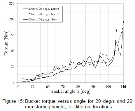
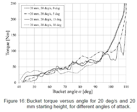
Figure 16 shows the variation of the bucket torque as a function of the angle of attack of the sliding base (and bucket assembly).
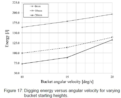
The torque versus bucket angle data was integrated to determine the energy required to fill the bucket volume, in the various test configurations. The energy determined in this manner accounted solely for filling the bucket with material as the buckets closed. It does not account for the energy required to raise the buckets above the muck pile. This is shown in figure 17 which shows the variation in energy as a function of nominal bucket angular velocity and bucket starting height. The energy was calculated for one bucket and doubled to model the complete digging process.
4 Discussion
4.1 Motion of particles
Preliminary experiments were conducted using 19 and 25 mm diameter plastic spheres and 13 mm decomposed granite stone particles for the purpose of gaining insights into particle motion, as the clamshell buckets closed. During digging it was apparent that the particles immediately in contact with the buckets initially moved in the same direction as the bucket jaws (i.e. deeper into the muck pile) while particles on the surface enclosed between the two buckets began to move towards the mid-plane between the buckets. Moving particles on the surface and ahead of the two opposing buckets began to converge and encounter resistance. They then began to move upwards into the interior of the buckets, as well as tangentially along the inner surfaces of the buckets. As the buckets neared the end of their stroke, the upwelling of particles in the bucket interior caused them to spill over and fill the remaining void in the buckets. In the case of the spheres this cascading was smooth while for the case of the 13 mm aggregate this was limited due to the surface roughness and associated friction. The angle of the material in the buckets was thus steeper for the aggregate than for the plastic spheres. In both test cases the starting position of the buckets was 30 mm above the particles and the buckets were not completely filled at the end of the bucket stroke.
In later experiments where the starting height was reduced, the buckets became overfilled and would not close properly since the buckets used in the experiment did not have openings at the top to allow particles to escape. In real world applications it is therefore advisable that the geometry of the buckets be designed such that the starting point for digging is when the buckets are in contact with the muck pile, and that the buckets are completely filled when they close from this starting position. This would make the efficiency of loading the highest. Buckets should also have openings at the top in the event that more material is scooped than the volume of the buckets can accommodate.
The particular geometry of the buckets and links that were used in the experiments resulted in a fairly shallow excavation. This is advantageous in a real world application as it allows the buckets to operate fairly efficiently when the layer of blasted material becomes shallow. There is an opportunity to exploit this further by incorporating a multi-linkage mechanism to control the bucket motion such that after initial penetration of the muck the bucket jaws follow a shallow digging profile. This will address the issues experienced by the Cactus Grab which becomes ineffective in digging in shallow muck piles, and will reduce the energy required to scoop a volume of material. In figure 17 the zero mm starting height (which resulted in a deeper digging profile) required significantly higher energies to scoop the material than the cases where the profile was shallower.
4.2 Experimental results
4.2.1 Bucket starting position and angular velocity
The experimental data depicted in the figures represent typical data that has been selected from the series of tests that were conducted. Figure 12 shows torque versus bucket angle data for tests conducted at a bucket starting height of 0 mm (i.e. buckets in contact with the material bed), for different angular velocities. The results were smoothed using a 3 point un-weighted moving average. The torques were attributed solely to the resistance of the material, as friction in joints and within the cylinder, as well as the weights of the buckets and links, were accounted for in average cylinder forces (as given in table 2), which were subtracted from all the experimental results. Figures 13 and 14 are similar to figure 12, but for bucket starting heights of 10 mm and 20 mm respectively.
From figures 12 and 13 it can be seen that average torques up to a bucket angle of about 65 degrees were similar for all three angular velocities, at bucket starting positions of 0 mm and 10 mm respectively. After a bucket angle of about 65 degrees, significant deviations occurred together with local peaks in the bucket torque (associated with the formation of blockages by means of wedging and interlocking of the particles, and subsequent breakdown of the blockages). This interlocking and wedging effect led to a number of instances at the lowest angular velocity where the material blockage was sufficient to stall the bucket motion before the end of its stroke. These results were discarded. At higher angular velocities there appeared to be more particle momentum (or fluidisation) and less likelihood of wedging and interlocking. This resulted in fewer peaks in the bucket torques for the test cases with higher angular velocities. Table 3 shows typical results of the number of peaks measured in the graphs in figures 12-14.
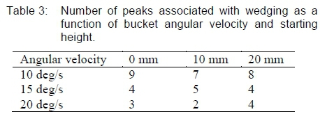
It is evident from table 3 that higher angular velocities were beneficial in reducing the potential for interlocking of the particles. It is anticipated that this effect would not be seen when digging smaller particles such as gravel or sand, though.
From figures 12 - 14 it is evident that the average torque at a bucket angle of 100 degrees (towards the end of its stroke) reduced as the bucket starting height was increased: at 100 degrees bucket angle the average torque was approximately 160 Nm for a bucket starting height of 0 mm, 100 Nm for a bucket starting height of 10 mm, and 75 Nm for a bucket starting height of 20 mm. Thus significantly lower torques were experienced at increased bucket starting heights. The relevance of this finding is as follows. Firstly, the buckets were not being overfilled, and secondly, the shallower penetration of the buckets into the muck pile resulted in lower bucket torques because the particles were less constrained the nearer they were located to the surface of the material. As with the finding relating to the particle motion visualisation, the practical implication is that it would be better to move the bucket pivot point upwards in order to dig shallower and to gather material in a motion that has a significant lateral motion associated with it.
A CAD analysis of the volume enclosed by the buckets was conducted for the two cases where the bucket was in contact with the surface and 20 mm away from the surface, prior to closing of the buckets. Since the bucket surface was not cylindrical, an assumption was made that the material that would flow into the bucket was based on a circular tip path of the inside surface of the bucket edge. With this assumption the theoretical volume of material captured by the buckets was 6.59 dm3 (for the case where the bucket starting height was 20 mm above the surface of the material), and 8.25 dm3 (for the case where the bucket was in contact with the material). As was mentioned earlier the theoretical bucket volume was 6.50 dm3- This confirms the observation that the bucket would be completely full when the starting height was 20 mm and overfilled when the starting height was zero mm, and would account for the increased torque, as about 25% more material was being scooped into the buckets. The mass of particles scooped was not measured during the experimentation stage. This would be a useful measurement in future test work to verify these observations, and to determine specific energies.
4.2.2 Proximity to a smooth boundary wall
Figure 15 shows a comparison of bucket torques for a starting height of 20 mm and angular velocity of 20 deg/s with the buckets positioned at three locations: centre of the material bed, against the front polycarbonate boundary (with the flat face of the buckets parallel to the boundary), and with the curved face of the bucket positioned against the side of the muck box (lateral boundary). These tests were conducted in order to simulate shaft cleaning where the Clamshell buckets may be positioned with either the flat surfaces or the curved surfaces of the buckets located against the shaft sidewall.
In the experiment both boundary surfaces were smooth (unlike the rough sidewalls that would be expected in shaft sinking). For these test conditions there was a marginal reduction in torque when the buckets were positioned against the front boundary, up to a bucket angle of about 80 degrees, after which significant peaks were noticed in the bucket torque. The lower torque was ascribed to particles at a shallow depth initially moving freely adjacent to the smooth boundary. However, later in the bucket stroke, for deeper particles, there was more confinement against the front boundary as compared with tests in the centre of the material bed, where particles in contact with the buckets could move laterally away from the buckets. In the case of the front boundary, particles could only move ahead of the buckets, which caused additional resistance. This was confirmed by visually observing the particle motion against this boundary. It is expected that in the case of a rough boundary, the bucket torques would increase substantially due to confinement and interlocking of particles with the undulations in the sidewall. For the lateral case and the centre case there is little difference in the bucket torques. The implication is that if the curved surface of the bucket is located against the sidewall then there should not be a significant change in the bucket torques, but, practically, material will be left in the corner which would require an additional method of cleaning.
4.2.3 Angle of attack
Figure 16 shows bucket torques for different angles of attack of the bucket assembly. Four angles of attack were considered: 0 degrees, 5 degrees, 15 degrees and 30 degrees, from a bucket starting height of 20 mm of the upper bucket. The average bucket torques shown in the figure were similar towards the end of the bucket strokes, with the torque measured for the highest angle of attack being marginally lower in the middle of the stroke.
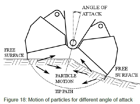
Visually, it appeared that material moved into the buckets more easily at higher angles of attack. Figure 18 shows how this could be possible. When the buckets were angled the jaws had a shallower tip path relative to the surface of the material (which implied less resistance). For successive digging tests, a free surface developed that was not level. This also allowed material to expand into the interior of the buckets easier than if the surface of the material was level and the angle of attack was zero relative to the vertical. One of the difficulties that was encountered, though, was ensuring that the bucket volume was completely filled.
It is anticipated that in real shaft cleaning applications it would be advantageous to start cleaning in the centre of the shaft and work progressively outwards, as this would reduce the confinement of the particles and should result in lower torques. However, one of the possible consequences of digging at a non-zero angle of attack is that it may not always be possible to ensure that the buckets are completely filled. This possibly accounted for some reduction in the bucket torque for the 30 degree angle of attack in figure 16, the practical implications of which need to be explored further.
4.2.4 Energy required to fill buckets
Figure 17 shows the energy required to fill the bucket volume as a function of the angular velocity, for the three bucket starting heights of 0 mm, 10 mm and 20 mm. At a bucket starting height of 0 mm (i.e. buckets in contact with the material bed) the energy that was required to fill the buckets ranged from 164 to 197 J, while at a starting height of 20 mm the energy varied from 73 to 133 J.
From this data it is apparent that although lower angular velocities do result in more peaks in the torque data, the average torques are lower than for higher angular velocities and therefore result in lower energy required to fill the buckets. The energy that the buckets impart to the particles at higher angular velocities is thus seen in the amount of energy required to fill the buckets. There is thus a trade-off between a need to consume the least amount of energy (lower angular velocities), while at the same time preventing wedging and bucket stall (higher angular velocities).
4.2.5 Effects of scaling
The research made use of a 1/6th scale model clamshell mucker where the scaling factor was chosen largely for practical reasons. Particle sizes of 13 mm were chosen which would be representative of particles of around 80 mm in size in the real system. While it is known that scaling results in granular materials can be problematic, Põschel et al16 indicated that lengths may be scaled linearly, but that material properties would also need to be scaled in order for the scaled system to be representative of the full size system. In this research it was not possible to scale the elastic constant (relating to particle stiffness) and dissipative constant (which predicts a loss of normal force on particles during interactions). Of these the elastic constant is linearly scaled while the dissipative constant is scaled by the square-root of the scaling factor.
For the research conducted in the 13 mm aggregate the actual elastic constant of the scaled system was 6 times too high and the dissipative constant was approximately 2.5 times too high. The effect on the scale model system was assessed as follows. If particle stiffness was too high in the scaled system it would result in the volume of particles entrained in the buckets rapidly becoming rigid as the buckets closed, and was likely to result in the formation and breakdown of significant peaks in the bucket torque, as was observed. In a full scale system it is anticipated that the peaks will still be present but their relative amplitudes are likely to be reduced somewhat. In the case of dissipation, in the scale model system the dissipative part of the normal force (based on a visco-elastic model for energy loss) was higher than it would be in the full scale system. This would predict higher energy losses in the particle interactions in the scale model system as opposed to the full scale system. The consequence is probably that in the full scale system the particles will move more freely as less energy is lost in the particle interactions.
According to Põschel et al16 the parameter time in the scaled system should be related to time in the full size system by the square-root of the scaling factor. This would imply that in the full scale system the angular velocity would need to be approximately 2.5 times that of the scale model in order to see the same features (i.e. in the range of 25 - 50 deg/s).
4.2.6 Relevance to Lashing in Shaft Sinking
The following points are of particular relevance to lashing during shaft sinking:
1. Buckets should be designed with openings at the top so that they cannot be overfilled.
2. The optimum point for starting of the digging motion should be where the buckets are in contact with the muck pile, and such that the buckets are completely filled when digging commences from this point.
3. A shallower scooping of material will result in lower forces and less propensity for wedging of particles. This will also be beneficial towards the end of the lashing phase where the layer of muck becomes shallow.
4. Higher angular velocities may be beneficial in preventing interlocking and wedging of particles due to the particles being energised, but will result in higher energy requirements, and potentially higher wear rates. In the full scale system the angular velocity should be roughly 2.5 times that used in the experiments in order to see similar effects.
5. Angle of attack of the buckets may play a role in reducing the bucket torques by reducing confinement of the particles. This has bearing on the procedure for lashing in that it should start centrally within the shaft and work progressively outwards.
6. Particles adjacent to a sidewall have a higher degree of confinement. If the bucket surfaces are oriented parallel to the sidewall it could lead to higher incidences of particle interlocking. In modern Clamshell loaders the bucket faces are convex instead of flat which may improve this situation.
5 Conclusions
1. A 1/6th scale Clamshell Mucker was developed and tested in plastic spheres and 13 mm decomposed granite particles. This represented particles of roughly 80 mm diameter for the full scale. Since fragmentation should ideally be 125 mm for mechanical loading, and since 70 - 80% of blast fragments are reported to be fine it was felt that full size particles that are 2/3 of the ideal value would be fairly representative in the experiment.
2. Measurements of actuating cylinder pressure and angular displacement of the buckets were made, and the data converted to bucket torque due to the reaction of the particles. Test parameters included bucket starting height, bucket angular velocity, proximity to boundary, and angle of attack.
3. For particular bucket starting heights the measured bucket torques for different angular velocities were similar.
4. Bucket starting heights of 0 mm were associated with over-filling of the buckets, and compression of particles, while at a starting height of 20 mm the buckets were completely filled upon closure.
5. The average torque just prior to bucket closure (i.e. when the two bucket jaws come into contact with each other) reduced significantly depending on the starting height of the buckets (160 Nm for starting height of 0 mm and 75 Nm for starting height of 20 mm). This was related to overfilling of the buckets in the 0 mm case.
6. Lower angular velocities resulted in higher prevalence of bucket stall due to formation of blockages, as a result of wedging and interlocking of particles. A minimum angular velocity of 10 deg/s in the experiment (or roughly 25 deg/s full scale) would reduce the likelihood of bucket stall. In the experiment higher angular velocities resulted in increased fluidisation of the particles and there was less likelihood of formation of obstructions and bucket stall.
7. Smooth boundary conditions did not affect the average bucket torques significantly, but did result in significant peaks in bucket torque in the case of the front polycarbonate boundary. This was due to the additional constraint on particles ahead of the bucket not being able to move laterally, and was confirmed visually.
8. The energy required to load particles into the buckets was least for lower angular velocities and for increasing bucket starting heights. There was a limitation, however, that the buckets' starting height could not exceed 20 mm above the surface of the muck as, for beyond this particular bucket geometry, the buckets were not be completely filled. It was also observed that the angular velocity of the buckets should exceed 10 deg/s in order to prevent bucket stalls.
6 Recommendations
• The top section of buckets should be removed so as to allow spill over of excess material in the event of the buckets being over-filled. The bucket geometry should be modified in order to allow the buckets to be completely filled when their starting position is located against the material bed as this will make the digging process easier. In addition, the ability to dig at a shallower depth should be considered in relation to a modified jaw tip path.
• The mass of the material scooped should be measured as an additional test parameter, to be used to correlate against the digging energy and to see to see if there is an optimum bucket fill factor.
• Additional tests should be conducted adjacent to a rough boundary to determine the effect that this has on the bucket torques.
• The effect of scaling should be investigated further to enable more reliable predictions of performance of a full scale system.
7 References
1. Moss ST, Development of a scale model clamshell mucker and validation by discrete element modelling, MSc Thesis, University of the Witwatersrand, Johannesburg, 2011. [ Links ]
2. Morgan G, Investigation into current shaft sinking processes with a view to proposing improvements in work practices with regard to productivity and safety, MEng Investigational project report, University of the Witwatersrand, Johannesburg, South Africa, 2015. [ Links ]
3. Wakefield T, Approaches to improve safety and recover lost productivities in vertical shaft sinking by making use of Industrial Engineering and risk driven 3-D modelling techniques, The Southern African Institute of Mining and Metallurgy Shaft Sinking and Mining Contractors Conference 2009, Johannesburg, South Africa, 2009.
4. Kratz T and Martens PN, Optimization of mucking and hoisting operation in conventional shaft sinking, Mining Report 151, 2015 (1), 38-47. [ Links ]
5. MacGillivray DM, High speed shaft sinking techniques in South Africa, Proceedings: 1979 Rapid Excavation and Tunneling Conference, Atlanta, Georgia, June 18-21, 1979, Volume 2. Editors Maevis, A.C., Hustrulid, W.A.
6. ASME Engineering History Landmarks, The EIMCO Rocker Shovel Loader Model 12B, ASME International, 2000, Miner's Plaza, Park City Utah. https://www.asme.org/about-asme/who-we-are/engineering-history/landmarks/212-eimco-rocker-shovel-loader-model-12b.
7. Graham C and Evans V, History of mining - the evolution of shaft sinking systems (Part 5), Shaft sinking from 1940 - 1970: The golden age, CIM Magazine, Canadian Institute of Mining, Metallurgy and Petroleum, March/April 2008.
8. Douglas AAB and Pfutzenreuter FRB, Overview of current South African vertical circular shaft construction practice, Shaft Engineering, March 1989, Institution of Mining and Metallurgy, London, England, 137-154.
9. Martin CJH and Harvey S, Sinking of the Asfordby Mine shafts, Shaft Engineering, 1989, Institution of Mining and Metallurgy, London, England, 289-296.
10. Dengler WR, Underground mining methods handbook. Society of Mining Engineers of the American Institute of Mining Engineering, Shaft Machines, 1982, 1263-1266.
11. Obert L, Opening and development, Society of Mining Engineers (SME), Mining Engineering Handbook, 1973, 1 (10), 10.2-10.104. [ Links ]
12. Stout KS, Mining methods and equipment. McGraw- Hill, New York, USA, 1980.
13. Joy Global, Shaft sinking equipment product overview. Joy Global, USA, 2015.
14. Moore E, Building a better shaft mucker, CIM Magazine, Canadian Institute of Mining, Metallurgy and Petroleum, October 2015.
15. Coetzee CJ, Els DNJ and Dymond GF, Discrete element calibration and the modelling of dragline bucket filling, Journal of Terramechanics 2010, 47, 33 - 44. [ Links ]
16. Póschel T, Salueña C and Schwager T, Scaling properties of granular materials, Physical Review E, 2001, 64 (011308), 1 - 4. [ Links ]
17. Britton SG and Lineberry GT, SME Mining Engineering Handbook, 2nd Edition, Vol. 2, Society for Mining, Metallurgy, and Exploration, Inc., Littleton, Colorado, USA, 1992. Editor: Howard L. Hartman. Section 17, 1543-1678.
Received 15 June 2016
Revised form 7 September 2016
Accepted 27 March 2017

