


Services on Demand
Article
 English (pdf)
 Article in xml format
 Article references
Indicators

Related links
-
 Cited by Google
 -
 Similars in Google
Share

 Permalink
R&D Journal
On-line version ISSN 2309-8988
Print version ISSN 0257-9669
R&D j. (Matieland, Online) vol.33 Stellenbosch, Cape Town 2017
Investigation of nozzle contours in the CSIR supersonic wind tunnel
B VallabhI, II; BWSkewsI
IFlow Research Unit, School of Mechanical, Industrial and Aeronautical Engineering, University of the Witwatersrand, Johannesburg, South Africa Email: beric.skews@wits.ac.za
IICouncil for Scientific and Industrial Research (CSIR), Meiring Naudè Road, Pretoria, South Africa Email: bvallabh@csir.co.za
ABSTRACT
The existing nozzle contour profiles of the CSIR's supersonic or High Speed Wind Tunnel (HSWT) produce weak waves in the test section region, which effectively degrades the air flow quality in the test section. This paper describes a calculation method developed to improve the flow quality in the test section region subject to the HSWT's limitations. The wind tunnel geometry and constraints were employed in accordance with the Sivells' nozzle design method and the method of characteristics technique to design the nozzle profiles for the full supersonic Mach number range 1<M<4.5 of the facility. Automatic computation was used for the profile design and a computational method analysed the test section flow characteristics. A boundary layer correction was applied to the profiles to account for the reduction in Mach number due to viscous effects. The method used, achieved uniform and shock-free test section flow, such that the Mach number distribution and flow angularity were within the acceptable quality limits of the HSWT.
Additional keywords: wind tunnel; nozzle design; method of characteristics; computational fluid dynamics
1 INTRODUCTION
For a uniform Mach number distribution, mandatory for wind tunnels, unique shapes for the divergent section of the Laval nozzle are required for each test section Mach number. The current nozzle contour shapes in the High Speed Wind Tunnel (HSWT) of the Aeronautic Systems Competency, within the Council for Scientific and Industrial Research (CSIR) were imprecise because the input contours result in a Mach number reduction from the desired set point Mach number, as no boundary layer correction was applied to the profile shapes. In addition, the legacy nozzle contours, at some settings, manifested weak waves in the test area.
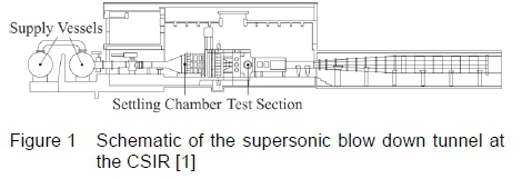
The CSIR's supersonic wind tunnel facility (HSWT), as illustrated in figure 1, is an intermittent blow down tunnel which uses a flexible nozzle to achieve freestream Mach numbers ranging from 0.6 < M < 4. Dry pressurized air, stored in high pressure supply vessels, is discharged into the wind tunnel using an automatic throttle valve. The nearly stagnant air in the settling chamber is accelerated in the converging nozzle section to a Mach number of unity at the nozzle throat. Uniform accelerating air then passes through the diverging section of the nozzle, which is designed to meet the required supersonic Mach number. Following the 450 mm χ 450 mm test section area, a convergent divergent diffuser decelerates the flow to near sonic conditions at the second throat. The flow decreases to subsonic speeds at the divergent section of the diffuser and the air exhausts back to the atmosphere.
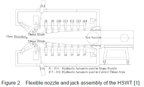
Two main hydraulic jacks at the top and bottom of the wind tunnel control the nozzle throat blocks that accurately position the minimal nozzle throat area as displayed in figure 2. Symmetrical nozzle profiles (about the test section centre line) are positioned by altering the throat block and the high-strength flexible steel plate in combination. Each plate is contoured by seven equally spaced hydraulic jacks, which are controlled by servo-valves that are signalled by fine resolution digital encoders. The jacks are able to move to a set of positions within the wind tunnel's mechanical and electrical limitations [1]. The contour design of the divergent portion of the supersonic nozzle is the primary objective of the current research, to yield uniform, parallel and shock-free flow in the test section over the entire supersonic Mach number testing range of the HSWT. It is imperative to design the contour profile for the flexible plate in conjunction with the fixed throat block curve. The end of the throat intersects the start of the flexible plate, creating an inflection point. This eliminates abrupt changes in curvature along the flexible plate and prevents unnecessary strain onto the plate. Downstream of the nozzle the pin-jointed test section region diverges marginally to account for the boundary layer growth within the test section.
Due to the high Reynolds number in supersonic facilities, the boundary layer is usually turbulent [2]. As the flow is accelerated in the nozzle, the boundary layer is negligibly thin at the throat and starts to become thicker downstream of the throat, as the Mach number increases. The thickest layer occurs within the test section region, which is the region of utmost importance for developing uniform flow [2]. The test section of the HSWT is fixed, with walls that are not perforated and sidewalls that are immovable and do not diverge to compensate for the displacement thickness of the boundary that develops over them. As mentioned previously, the test section upper and lower walls do diverge, but this is insufficient to correct for the boundary layer effects over all test Mach numbers. Hence, the sole technique to correct the nozzle exit Mach number for boundary layer development along the nozzle itself and along the side walls (without substantial modifications to the HSWT facility) is to adjust the throat such that the effective area ratio is that of the desired freestream Mach number, in the presence of the boundary layer.
The Method of Characteristics (MOC) is a numerical technique used to define the properties of supersonic flows in the presence of varying boundaries such as in a wind tunnel or in the presence of some aerodynamic configuration in a supersonic airstream [2]. An application of the method of characteristics is the design of the contours of supersonic nozzles. James C. Sivells' nozzle design method [6] encompasses the design of two-dimensional supersonic nozzles, maintaining continuous curvature of the nozzle thereby ensuring that the flow is parallel, uniform and shock free in the test section region.
2 METHOD
An analytical technique adapted from Sivells' nozzle design method allows for a variety of specified initial conditions, which need to be optimised such that the resulting nozzle profiles produce the best possible flow conditions within the operational region of the HSWT facility. For purposes of automatic optimisation and computation of the nozzle contours, a program was created in MATLAB which computed the uncorrected nozzle profiles for each Mach number set point.
A computational study was exercised to evaluate the nozzle profiles in order to ascertain the Mach number distribution across the test section, determine whether the calculated profiles produce shock free flow in the test section, as well as use the computational results to correct the profiles for the viscous effects experienced in the wind tunnel. A boundary layer correction was thus applied, and the profiles were computed again using the developed MATLAB programme and a verification of the boundary layer corrected profiles was completed using the Computational Fluid Dynamics (CFD) package STAR-CCM+ V9.06.
2.1 Method of Characteristics
This method is based on the mathematical theory of lines or curves in two-dimensional flow and surfaces in three-dimensional flow associated with the solution of certain nonlinear differential equations of the velocity potential. [3]. The method of characteristics is the most frequently utilized method for designing the contours of a two-dimensional supersonic converging-diverging nozzle for smooth, uniform and shock free flow. Wind tunnel nozzles are generally long with slow expansion whilst rocket nozzles expand rapidly to produce short nozzles that minimize weight [3].
For the case of a converging-diverging supersonic wind tunnel nozzle, presented in the schematic in figure 3, the subsonic flow in the convergent portion of the nozzle is accelerated to sonic conditions at the nozzle throat region. A sonic "line" exists which is marginally curved, but for most applications it is assumed to be straight. Downstream of the sonic line, the nozzle diverges in the expansion section and converges in the straightening section of the nozzle, to meet the test section region.
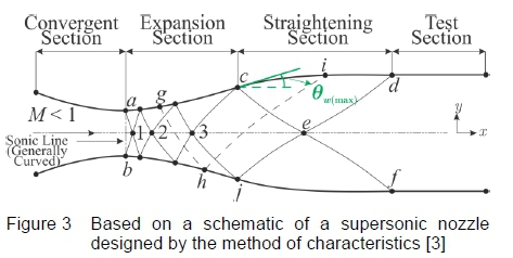
If the upper half of the nozzle is considered, then the angle of the nozzle wall with respect to the horizontal direction, 𝜃W, initially increases in the region referred to as the expansion section, where expansion waves are generated and propagate across the flow downstream as they reflect from the opposite wall of the nozzle. This region consists of both left and right running characteristic lines, which is defined as a non-simple region where the characteristics are curved lines. The shape of the expansion section is usually arbitrary and varies to accommodate the required nozzle length. An inflection point exists on the nozzle contour aft of the expansion section, where the maximum allowable wall angle is achieved, 𝜃W(max) . Downstream of the inflection point, the nozzle wall angle decreases until the wall becomes parallel to the direction of flow at the exit of the nozzle. This region is referred to as the straightening section which is designed to cancel the expansion waves originating in the expansion section. Figure 3 illustrates the manner in which the expansion wave at g, originating in the expansion section is reflected at h, on the opposite side of the nozzle wall and cancels at i, in the straightening section of the profile. Downstream of points d, e and /, lies the test section wall where the flow is uniform and parallel at the desired Mach number [3].
2.2 Sivells' Nozzle Design Method
Numerous supersonic wind tunnels incorporate flexible plate nozzles to allow for multiple Mach number ranges to be tested [2]. The flexible plates, frequently supported at discrete points, require continuous curvature such that the theoretical aerodynamic nozzle shape matches the elastic curve of the plate when shaped.
Foelsch [4] indicated that the straightening section of a nozzle profile can be computed analytically by assuming that the flow is radial at the inflection point of the nozzle. As a result the flow is assumed to originate from a single source point upstream of the inflection point.
Presently in the design of supersonic nozzles using the method of characteristics, the characteristics have equal strength where the expansion waves are created in the expansion section and cancelled in the straightening section. The curvatures of the expansion and straightening regions have a finite positive and negative value (for the upper contour), respectively, as the angle varies along these sections. The curvature is discontinuous at the inflection point and the test section region since a pure reflection causes the curvature to be zero. Riise and Puckett's [5] supersonic nozzle design method ensures that the curvature of the contour is continuous by including a transition region following the expansion region where the characteristics are partially cancelled and partially reflected to ensure that the second (and third) derivatives of the contours are continuous.
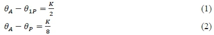
The Sivells' method incorporates the source flow computations from the Foelsch [4] method with the design of a continuous curvature supersonic nozzle, from Riise and Puckett [5], to provide the equations to determine the characteristic angles required to satisfy the nozzle length and nozzle height as well as maintain continuous curvature between the expansion and straightening regions. Figure 4 assumes that the flow is radial where the arc 𝜃O, of a circle around the apparent source, is an equipotential line along which the Mach number is constant. Point A refers to the inflection point, with Point U the nozzle exit having zero curvature. The points Ρ and Τ are defined as the characteristic points lying at the start of the straightening section [6].
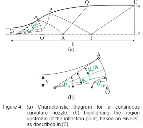
The upstream characteristic reflecting off the wall at point Ρ intersects the arc AO, where the flow inclination crossing the arc is 𝜃𝑃1. The inflection point (A) angle is BA. The parameter Κ (constant value) is an angle defined by the inflection point angle which is used to define the rate of change of curvature of the nozzle profile as represented in equations 1 to 2, which are used to interrelate B1P, 𝜃𝑃, BAand K, where BPrefers to the angle at point P.
The Prandtl-Meyer angle, v, is defined as the maximum angle through which supersonic flow changes direction isentropically. This angle is a function of Mach number and a property of flow that limits the rate of change in nozzle area.
Sivells [6] defines the Prandtl-Meyer angle of the characteristic point P, vP(equations 3 and 4) in terms of the Prandtl-Meyer angle of the test section, vT, defined by the exit Mach number, and the wall angle at the characteristic point, Bp. Furthermore, the wall angle can be expressed in terms of the inflection point angle, BAand the parameter K, where the parameter Κ ranges from zero to a maximum value of 4𝜃A. For practical purposes this value should be greater than 2𝜃A
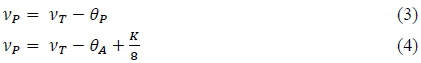
Similarly the Prandtl-Meyer angle at the inflection point, vAis defined in equations 5 and 6, with the flow inclination represented by the Θ1Ρ value.
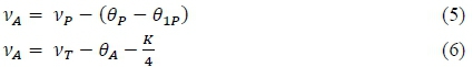
The Prandtl-Meyer angles at the contour (wall), vw, are described in terms of the Prandtl-Meyer angle at A (vA), the wall angle (θw) and the flow inclination of any fluid that crosses the arc AO (θ1) from the inflection point A to the characteristic point P. For the characteristic point Ρ to the end of the nozzle at point U, the Prandtl-Meyer angles at the contour (vw), are equivalent to the Prandtl-Meyer angle at the test section (yT), minus the wall angle (θw), as defined in equations 7 to 8 respectively. The wall angles are computed via the method of characteristics for supersonic nozzle design [6].
Referring back to figure 4, the arc AO is divided into r equal parts, where the angle  contains k of these r parts so that:

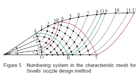
The characteristic mesh is hence created by initiating the characteristic lines on the arc AO at the midpoint of each of these r parts, termed as points w, x, y and z, as portrayed in figure 5. Moreover, the points on the nozzle contour are numbered consecutively from 1 to (2r + k), with the first point located aft of the inflection point (Point 1). Exercising Sivells' definitions, the inflection point corresponds to a point number of - and not zero as is typically used in the method of characteristics. Correspondingly, if one assumes that θ1P= 0.250,4, then from equation 1, Κ = 1.5θA. Incorporating these values into equation 9, results in k = 0.75r. Assuming that r = 4, hence k = 3 and points P, Q and U have values of  and
and  which calculate to values of 3.5, 8.5 and 11.5 respectively.
If m denotes the point number, equations are specified for the wall angles where k, m and r are integers, as follows.
Subsequently, all the remaining angles downstream of the inflection point, lying in the characteristic mesh, but not on the contour, are evaluated, at each characteristic point, using the traditional method of characteristics procedure. In summary, by using the method of characteristics with the constraints and criteria defined by Sivells'[6], practical nozzle shapes with continuous curvature, specifically suited to the HSWT could be obtained.
3 DESIGN OF SUPERSONIC NOZZLE PROFILES FOR THE HSWT
3.1 Facility Constraints
The CSIR's HSWT nozzle incorporates a fixed converging section, a solid throat block (that is free to translate and rotate about a pivot point), a flexible steel plate and a fixed diverging test section region, all of which are interdependent, as represented in figure 6. These work in synergy to control the Mach number and flow quality in the operational section of the wind tunnel. Typically in wind tunnels of this nature, the inflection point occurs where the throat block and the flexible plate meet, which ensures that the stress in the plate is minimised by enabling a smooth profile in the flexible plate i.e. the curvature in the plate is continuous and has the same direction over the length of the plate, although the magnitude varies.
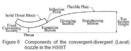
The standard procedure for designing a supersonic nozzle using the method of characteristics must be adapted to accommodate the HSWT nozzle constraints i.e. the solid throat block, the length of the flexible plate, the test section height and the fixed diverging test section region. This is necessary as the traditional method of characteristics produces profiles that are considerably short in length with steep wall angles. It is desirable to design profiles for the wind tunnel that are sufficiently long in order to minimize the wall angle thereby ensuring smooth curvature over the plate, as well as to utilize as many jacks as possible to shape the flexible plate. Furthermore, the designed nozzle profiles should keep the Mach number distribution along the test section to within 0.5% of the desired Mach number in the test section - a quality assurance criterion stipulated by the facility.
3.2 Analytical Technique Adapted from Sivell's Nozzle Design Method
Sivells' nozzle design method was adapted to incorporate optimised initial conditions that are within the geometric capabilities of the HSWT. The method followed can be divided into three broad segments, namely:
• A throat rotation procedure to optimise and match the inflection point angle and the constant Κ term which defines the rate of change of curvature of the nozzle profile.
• A source flow calculation, coupled with defining the characteristic mesh resolution.
• A traditional method of characteristics computation aided diagrammatically with a characteristic mesh.
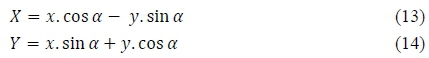
For a specified test section Mach number, M, the throat block orientation is to be determined by utilizing the throat geometry and rotating the throat block position until a suitable inflection point angle (Θ Α ) is met. The process commences with a one degree of freedom rotation, determined by the χ and y throat geometry coordinates and the rotational angle, a as highlighted by equations 13 and 14.
The gradient between two adjacent coordinates is then calculated, where only the coordinates for the positive gradients are applied to enable modelling of the throat block downstream from the throat only. This implies that no translations are required in the initial computations, since the coordinate system used in the computations is defined relative to the throat. Since the geometry of the wetted region of the throat block can be approximated (with high confidence) by a sixth order polynomial, the Cartesian coordinates for the inflection point (xAand yA) can be determined relative to the defined coordinate system. Due to the relatively complex geometry of the throat block, an iterative process to attain the required throat block rotational angle (a) for the optimised inflection point angle (Θ Α ) is incorporated into the solution process.
The ratio between the constant, Κ and the inflection point angle, Θ Α , referred to as Ktargethenceforth, is manipulated to adjust the curvature of the profile thereby modifying the contour to the required length. This parameter was incorporated into the procedure from the outset so that length adjustments of the profile can be made, in order to meet the geometric boundary conditions of the HSWT. This implies that the length of the profile is indirectly set as an initial condition by specifying Ktarget, rather than directly entering the length value into the procedure. It is worth recalling that practical values of the rate of change of curvature lie between 2Θ Α < Κ <4Θ Α i.e. 2< Ktarget<4 [6]. In the limit that K-target = 4, a maximum profile length for a specified test section Mach number is achieved. Since the physical throat block profile is used to determine Θ Α , this maximum computed length is also the maximum possible length geometrically possible in the facility, for the specified Mach number. For a given inflection point angle, the Κ value is calculated by rearranging equation 6 to 15 where the Prandtl-Meyer angle at the nozzle exit is known from the desired Mach number. The ratio of Κ to Θ Α is then computed, tested against the length parameter (Ktarget) and if it is not met, the throat block is further rotated. This forms part of the iterative process used to find the optimised inflection point angle (Θ Α ) by rotating the throat block, as discussed previously.

Once the optimised throat block position is determined for a specific test section Mach number, which meets all the physical constraints of the HSWT, the Sivells' nozzle design method [6] proceeds from the inflection point downstream, based on the assumption that flow at the inflection point, A originates from a source flow point, S along the axis of the nozzle, as depicted in figure 7. The fixed throat block of the HSWT has discrete χ and y coordinates with the inflection point located relative to the χ = 0 position, i.e. the throat location. The source flow point must be determined relative to this throat location such that the coordinates of the inflection point remains unchanged with respect to the throat location, as this has become the reference point for all computations.
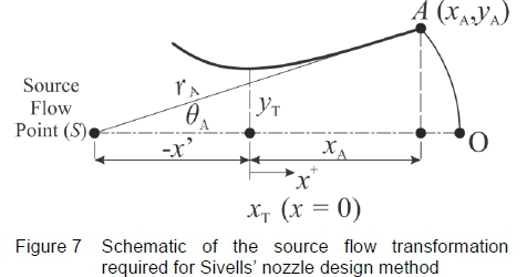
The location of the source flow point and hence the radius of the arc, AO, denoted as rA, must be referenced from the χ = 0 (at the throat) position, in order to develop a nozzle profile that is compatible at the optimised inflection point. It is known that the line SA intersects the nozzle axis at the initial inflection point angle, Θ Α , such that the gradient, mA, of line SA is:

As a result, the equation of the line SA is:

If we substitute the known coordinates of the inflection point, A (xAand yA) into equation 17, we can solve for the constant cA. However, since the source flow point is located on the nozzle axis, ys= 0 and xs = -x' such that x' = cA/mA. The arc of the radius, rAis hence:

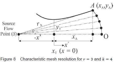
Furthermore, the characteristic mesh resolution (number of segments on the arc), r on arc AO is specified by dividing Θ Α into segments such that ΔΘ = θA/r as portrayed in figure 8, when r = 3 and k = 4. Each characteristic point, however, lies in the centre of each segment making the angle of the first characteristic point subsequent to the nozzle axis equivalent to θ1 = ΔΘ/2. The succeeding points will be calculated as θ = ΔΘ/2 + ΔΘ. Consequently, the last characteristic point will have an angle of θ3 = Θ Α - ΔΘ/2. The χ and y coordinates of these characteristic points are computed using traditional polar to Cartesian coordinate transformations, since the arc AO has a constant radius of rA.
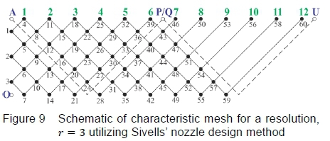
These points are then used to initiate the characteristic network, labelled vertically between A and Ο as 1, 2 and 3, in figure 9. The bold numbers at the top of figure 9 correspond to the wall points defined by Sivells' [6] in equations 10 to 12, and the points A, P, Q and U have also been included to correspond to the definitions outlined in section 3, figure 4. The characteristic network is shown in a rectangular manner in figure 9, for clarity.
A simple excel spreadsheet with a coarse mesh was initially used to understand the method to be followed. Thereafter, an automatic algorithm was scripted in MATLAB to assist with the method of characteristics computations with much higher characteristic network resolutions. The code also included the procedures to determine the optimised initial conditions by rotating the throat block, the source flow calculations, as well as post-processing functions for exporting the data in useable formats.
In summary, the adaption of the Sivells' nozzle design method for the current study focused on incorporating the HSWT facility constraints into the design method as boundary conditions. This included an optimisation procedure where the physical throat block geometry was rotated to achieve a suitable inflection point angle for a given Mach number, such that the length criterion (defined by  was satisfied. Thereafter, a source flow transformation was used to initiate the characteristic network for a specified resolution (r). Finally, the method of characteristics procedure was used to generate the nozzle contour for the desired test section Mach number.
3.3 Computational Method
Numerical flow simulations of the uncorrected and boundary layer corrected profiles were computed using the commercial flow solver, STAR-CCM+ V9.06, where a coupled flow solver was employed and the air was modelled as an ideal gas. An unstructured polyhedral cell based volumetric mesh was generated with a refined boundary layer mesh along the nozzle profile and side wall to adequately resolve the boundary layer region for the viscous simulations. Mesh independence studies were completed to ensure that the results were independent of the mesh resolution of the simulations [7]. Initially, Euler simulations of the profiles where completed to verify that the inviscid nozzle profiles generated by the method of characteristics computations produced acceptable flow in the test section of the HSWT. Thereafter, Reynolds-Averaged Navier-Stokes (RANS) computations were completed, using the Spalart-Allmaras turbulence model, of the same profiles to assess the viscous effects in the wind tunnel. It should be noted that although the MOC produces a two-dimensional nozzle profile, it was necessary to model the three-dimensional domain, since the boundary layer growth is not limited to the nozzle contour only, but develops along the side walls of the wind tunnel as well, consequently affecting the test section flow and the procedure to correct the nozzle contours for viscous effects.
4 RESULTS AND DISCUSSION
4.1 Designed Profiles
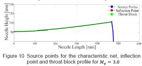
Theoretical inviscid, uncorrected (for boundary layer effects) nozzle profiles were generated using the MATLAB code, which governed the input parameters to Sivells' [6] technique by using the HSWT's geometric constraints as boundary conditions. A brief discussion of a nozzle profile to produce an uncorrected nozzle exit Mach number of Me = 3.0 will be outlined, followed by the contours at particular Mach number set points. The value of the non-dimensional length parameter was set to Ktarget = 2.9 and a value r = 42 was used to initiate the characteristic network on the source flow arc to compute the nozzle profile to a test section height of y = 227.74 mm using the characteristic method. The source points of the characteristic net and throat block geometry for the above configuration is demonstrated in figure 10.
The resultant wall contour as calculated using Sivells' nozzle design method [6] coupled with the traditional method of characteristic calculations is shown in figure 11, where the straightening section has been inserted between the fixed throat block (expansion section) and the fixed test section regions of the HSWT. The straightening section does not end precisely at the test section inlet. This was expected since the mechanical nozzle of the HSWT is designed such that the Mach number can be rapidly changed between runs in the facility. As a result, rather than having unique expansion sections for each Mach number setting, the HSWT incorporates a fixed throat block design that can be rotated and translated. The throat block or expansion section profile was designed for the mid-Mach number range of the facility rather than the maximum operating Mach number, which results in a higher flow accuracy over a greater range of operating Mach numbers in the HSWT [8]. For this reason, some of the calculated profiles do not terminate precisely at the test section inlet, even when the throat block rotational position optimisation procedure reaches the geometric limits of the HSWT facility, as is the case for the calculated profile being discussed. However, the nozzle has a finite number of control points that need to be moved to a suitable position when the profile is set in the facility, even when the calculated nozzle profiles fall short of the jacking positions.
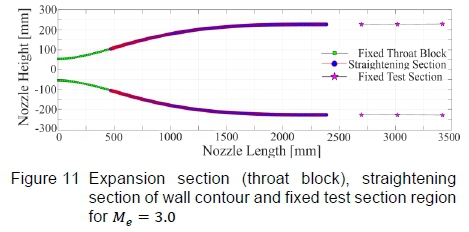
The profiles were hence artificially lengthened, subsequent to the method of characteristics calculations, to meet the test section precisely. The lengthening was not done arbitrarily, but ensured that equal curvature and tangency of the profile was maintained at the nozzle exit and test section inlet, thereby following the elastic curve of the flexible plate. This was possible since the pin-jointed, diverging test section region is essentially a curve as well. The spline that joined these positions was used to extrapolate the Cartesian coordinates of the lengthened section. Although the Ktarget value for this particular profile could be increased to lengthen the profile, increasing this value to Ktarget = 4.0 would lengthen the profile beyond the fixed test section, which is impractical. Furthermore, in the lower Mach number ranges, even when the non-dimensional length parameter is set to a maximum value of Ktarget = 4.0, the profile does not meet the test section, so lengthening is necessary. The generated profile will be used as an example to validate the lengthening technique, and verify that the additional section does not perturb the flow through the HSWT. This was completed using a CFD analysis, as documented in Sections 4.2. It should be duly noted that characteristic network resolution sensitivity studies were conducted to determine the numerical errors associated with the finite characteristic grid, where it was found that the error tends to zero when r > 40.
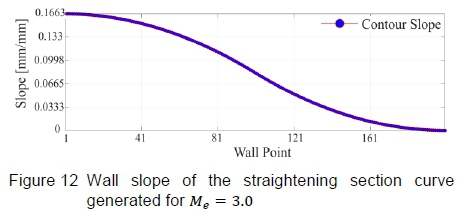
Continuing with the discussion of the generated profile for Me = 3.0, it is inherent to Sivells' method that continuous curvature of the plate is ensured, by explicitly defining the wall angles for each point on the contour. Once the profile was generated, the continuous curvature criterion was verified by taking finite differences from the inflection point A, towards the nozzle exit. The resultant wall slope for each point of the straightening section is presented in figure 12, which shows that the slope of the contour is a smooth curve, thereby ensuring continuous curvature. This is necessary to ensure that the plate's elastic curve can match the calculated aerodynamic curve.
Nozzle contour profiles were calculated for all HSWT supersonic Mach numbers in increments of ΔMe= 0.1 as these are the specified requirements of the HSWT. A comparison of the uncorrected contours, in ΔMe= 0.5 Mach number increments, is indicated in figure 13 highlighting the various throat heights whilst maintaining the correct plate length and test section height.

4.2 Computational Results of the Uncorrected Profiles
It is well known that the flow through the HSWT is viscous, but inviscid flow solutions were first completed to verify that the computed nozzle contours produce test section flow that is devoid of irregularities. Thereafter, viscous flow simulations were completed. Figures 14 to 17 displays the final inviscid and viscous solutions, illustrating Mach number contours, followed by density gradient contours on the vertical symmetry plane. The density gradient visualisation technique is advantageous in verifying whether the test section is devoid of shock and expansion waves. The difference in the maximum Mach number on each scale should be noted where the elevated Mach number (i.e. greater than Me= 3.00) for the inviscid solution is due to fact that the profile was generated for a terminal height of y = 227.74 mm (end of the flexible portion of the nozzle), which increases to 229.675 mm along the fixed test section region (a feature built into the HSWT to potentially compensate for the wall boundary layer). The maximum Mach number decreases for the viscous solutions, in comparison to the inviscid case, since a finite boundary layer develops along the nozzle contour and the side walls of the tunnel. Close to the nozzle wall, the boundary layer thickness for the viscous approximations can be estimated by the high gradients detected in the near-surface flow, as shown in figure 17. However, it does tend to exaggerate the boundary layer thickness in the test section, since the density gradient scale was finely set to expose flow gradients in the test section. From a qualitative assessment of these contours, the generated nozzle profile appears to produce uniform test section flow, both in the inviscid and viscous regimes, notwithstanding the lower than desired nozzle exit Mach number for the viscous flow simulations.
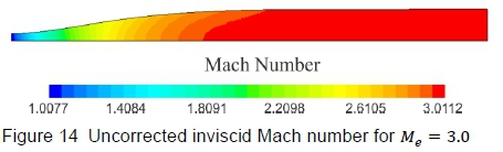
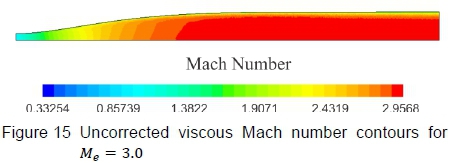
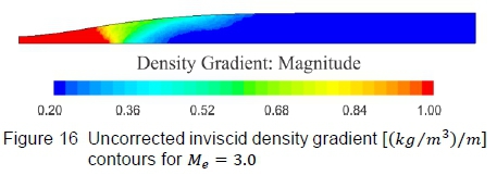

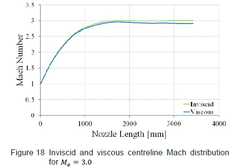
Figure 18 demonstrates the variation in Mach number along the wind tunnel's centreline for the inviscid and viscous runs, which highlights the Mach number roll-off due to the viscous effects. It is quite evident that as the boundary layer thickens progressively along the walls, the flow Mach number decreases correspondingly. For this profile, which was designed to produce a test section Mach number of Me= 3.00, the actual mean test section Mach number predicted by the viscous CFD simulation is Me= 2.914, which is well below the target value, implying that a correction is required.
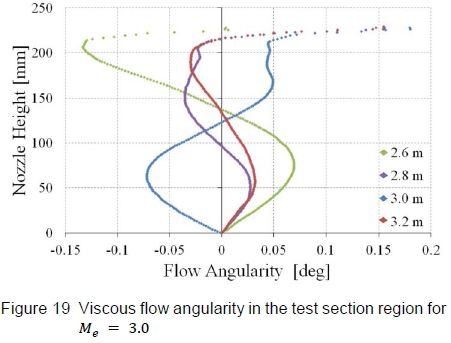
Nonetheless, to quantify the flow quality in the test section, the flow angularity diagnostic parameter, extracted from the viscous CFD simulations, will be used. Figure 19 displays the flow angularity at various χ stations along the test section, referenced from the throat (x = 0). Flow angles reported above y = 200 mm are neglected since they lie in, or close to the viscous boundary layer along the contour walls. A maximum flow angle of approximately 0.13° is reported at χ = 2.6 m. This value of 0.13° is taken close to the test section walls where the flow angularity is affected by the boundary layer growth on the walls. The acceptable flow angularity in the HSWT is ±0.2°, which confirms that the profiles designed in these studies produce test section flow quality that falls within the acceptable tolerances of the HSWT facility. It should be noted that for a symmetrical nozzle profile (as modelled in this study), the flow angularity at the centreline is zero. Typically, wind tunnels of this nature require the flow angularity accuracies of ±0.2° along the centreline, due to the inherent mechanical inability to match the theoretical profiles both for the upper and lower contour exactly.
4.3 Boundary Layer Thickness Correction
The test section is expanded slightly along its length to compensate for the boundary layer growth on the nozzle as well as the side walls of the facility, but it is evident from the CFD analysis presented in the previous section that this small wall divergence does not make the HSWT self-correcting for viscous effects. The length of the contraction section (portion of the throat block upstream of the contour throat) has little effect on the boundary layer thickness at the nozzle throat and was excluded from the adjustment to correct the profiles for viscous effects. Based on the average test section Mach number produced by the uncorrected nozzle profile in the viscous CFD simulation (Me = 2.914), the effective area ratio was calculated. A boundary layer thickness correction procedure was followed [7] and the effective area ratio required to compensate for viscous effects was calculated where the new design Mach number was determined to be Me(corrected) = 3.093 i.e. a nozzle contour designed by the method of characteristics to produce an exit Mach number of 3.093 is required to get an average test section Mach number of Me = 3.00 in the presence of the boundary layer that develops along the walls of the facility. It should be noted that it is inadequate to simply adjust the throat to achieve the corrected area ratio with the rest of the profile remaining the same, because by moving the throat the entire expansion section shifts as well, and the uncorrected profile will not cancel all the expansion waves generated at the new throat block position. As a result, a completely new profile needs to be generated at the corrected design exit Mach number.
A comparison of the uncorrected and the corrected profiles is displayed in figure 20, where the change in throat height is quite evident, but it can also be seen that the entire profile has been altered along the nozzle contour. Both profiles were generated using the method of characteristics MATLAB code as discussed in section 3 and meet all the required conditions for compatibility with the test section, and satisfy the throat block's geometric constraints. So rather than displacing the nozzle contour outward by the boundary layer displacement thickness, which is the intuitive method to correct the area ratio but physically impossible in the HSWT facility due to the fixed test section, the current correction method speeds up the potential flow (outside the boundary layer) to the desired Mach number. The shortfall is that this method is computationally expensive because, firstly, the uncorrected profile needs to be generated. Thereafter, a viscous CFD analysis has to be performed to determine the effective area ratio with the boundary layer present. Then the correction procedure is applied and the corrected profile is generated at the new design conditions. This is followed by a viscous CFD analysis of the corrected nozzle contour to verify that the corrected profile, in fact, produces the desired test section conditions, as documented subsequently.
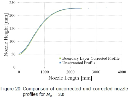
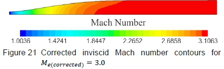
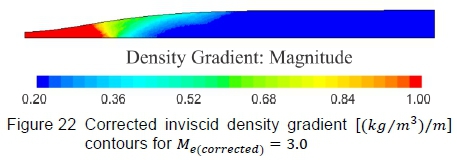
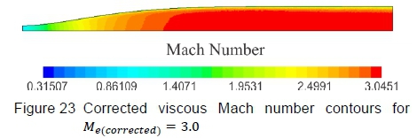
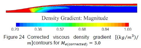
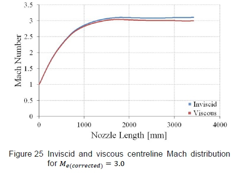
Figure 21 shows Mach number contours and figure 22 shows density gradient contours on the vertical symmetry plane, computed by the inviscid CFD simulation. Figure 21 highlights that the flow Mach number becomes uniform and figure 22 portrays the density gradients becoming negligible as the flow expands towards the test section, implying that the straightening section is effectively cancelling expansion waves generated in the expansion section. The viscous solutions are presented in figure 23, which shows Mach number contours, and figure 24, which shows density gradient contours. Except for the distinct boundary layer, the flow trends are comparable to the inviscid solutions, in that the Mach number becomes uniform and the density gradients detect no irregularities in the test section region. The Mach number distribution along the wind tunnel centreline is presented in figure 25, where the total Mach number deviation lies within ΔM = ±0.012 over the entire test section region with an average Mach number of 3.003. These results are acceptable for testing in the HSWT.
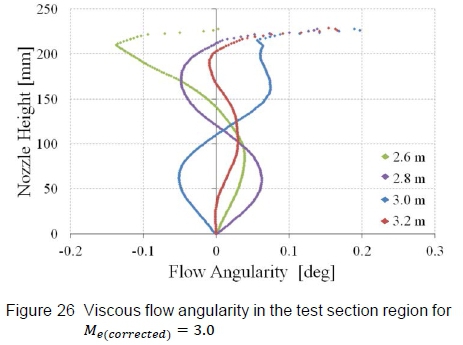
The flow quality, defined as the flow angularity in the test section region, is comparable to those of the uncorrected nozzle profile presented previously (maximum flow angle of approximately 0.13°), as seen in figure 26, and lies within facility specifications. Overall, the boundary layer correction technique developed in this study coupled to the characteristic method generates nozzle contours that produce the desired Mach number and flow quality in HSWT's test section, notwithstanding the thick, turbulent boundary layer developed along the walls.
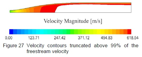
As mentioned previously, the boundary layer is overexposed by the density gradient contours due to the fine scale of the density gradients necessary to highlight the formation of test section irregularities. Figure 27 shows the velocity magnitude developed on the symmetry plane of a profile generated to produce an average test section Mach number of 3.00, where the contours have been truncated above the 99% of the freestream test section velocity. This then gives a better approximation of the actual boundary layer thickness developed along the nozzle contour, which appears to be marginally thinner than that exposed by the density gradient contours.
5 CONCLUSIONS
The CSIR's High Speed Wind Tunnel (HSWT) had theoretical supersonic nozzle profiles, implemented in the facility historically, that produces irregular test section flow, even after the profiles were experimentally modified in an attempt to alleviate the problem. After a thorough investigation, it was deemed necessary to completely redesign the nozzle contours of the HSWT to produce high quality test section flow. Of the diverse methods available for supersonic nozzle designs, the Sivells' nozzle design technique was found be to be the most appropriate. Since this characteristic method allows profiles to be generated from the inflection downstream, it could be adapted to include the geometric constraints of the fixed throat block and test section as boundary conditions, which governed the input parameters to the nozzle design technique.
A MATLAB code was used to compute the Cartesian coordinates of the nozzle profiles, where the nozzle designs were optimised to produce suitable profiles for each Mach number that maintained physical compatibility with the throat block and test section of the HSWT. All nozzle profiles designed in this study were evaluated using computational fluid dynamics. The Mach number distribution, flow angularity and density gradients produced by the profiles in the test section of the wind tunnel were evaluated against stringent HSWT tolerances before being accepted. The viscous CFD simulations were also used to correct the profiles for boundary layer development along the wind tunnel's side walls and the calculated nozzle profiles itself, producing the desired Mach number in the test section region of the facility. Overall, the designed nozzle profiles produces test section flow conditions that are devoid of shocks, expansions and other irregularities, have uniform flow and Mach number distribution, and the flow angularity falls within the acceptable quality limits of the facility.
References
1. K Naidoo, Dynamic Shock Wave Reflection Phenomena, PhD Thesis, University of the Witwatersrand, Johannesburg, 2011. [ Links ]
2. A Pope andKL Goin, High-Speed Wind Tunnel Testing, Wiley, New York, 1965.
3. J Anderson, Modern Compressible Flow with Historical Perspective, 3rd Edition, McGraw-Hill, New York, 2003.
4. K Foelsch, A New Method of Designing Two- Dimensional Laval Nozzles for a Parallel and Uniform Jet, North American Aviation, Inc., 1946.
5. HN Riise, Flexible Plate Nozzle Design for Two- Dimensional Supersonic Wind Tunnels, Jet Propulsion Laboratory Report, No. 20-74, California Institute of Technology, 1954.
6. JC Sivells, Design of Two-Dimensional Continuous- Curvature Supersonic Nozzles, Journal of the Aeronautical Sciences, 1955, 22(10), 685-692. [ Links ]
7. B Vallabh, Investigation of Nozzle Contours in the CSIR Supersonic Wind Tunnel, Masters Research Report, University of the Witwatersrand, Johannesburg, 2016. [ Links ]
8. A van Wyk, Design of Two-Dimensional Supersonic Wind Tunnel Nozzles having Continuous Curvature, National Mechanical Engineering Research Institute, Council for Scientific and Industrial Research, Pretoria, Republic of South Africa, 1972.
Received 17 February 2017
Revised form 23 June 2017
Accepted 25 June 2017

