


Services on Demand
Article
 English (pdf)
 Article in xml format
 Article references
Indicators

Related links
-
 Cited by Google
 -
 Similars in Google
Share

 Permalink
R&D Journal
On-line version ISSN 2309-8988
Print version ISSN 0257-9669
R&D j. (Matieland, Online) vol.33 Stellenbosch, Cape Town 2017
Design of a six-component side-wall balance using optical fibre sensors
FF PieterseI; PM BidgoodII; NF VazI
IWind Tunnel Balance Research Group, University of Johannesburg, Department of Mechanical Engineering Science, UJ, Auckland Park, South Africa. E-mail: ffpieterse@uj.ac.za
IIBalance specialist, Council for Scientific and Industrial Research (CSIR), Pretoria, South Africa. E-mail: pmbidgoo@csir.co.za
ABSTRACT
The requirements that a wind tunnel balance need to satisfy have become increasingly stringent. These requirements, as set out by the wind tunnel testing community, include: improved static force accuracy and resolution, increased stiffness, temperature compensation and immunity to electromagnetic interference (EMI). In order to satisfy these requirements, wind tunnel balance design philosophy needs to include alternative strain sensing technologies, alternative materials and alternative manufacturing techniques. This paper outlines the expansion of balance design philosophy to incorporate displacement sensors. This is done on a six-component side wall balance using optical fibre Bragg grating sensors (OFBGs). The balance employs the two-groove optical fibre method. This method has been demonstrated by Pieterse [1], to work effectively whilst offering significant balance design simplification.
Additional keywords: Wind tunnel balance, Side-wall balance, Optical fibre, Optical fibre sensing.
Nomenclature
FEM Finite Element Modelling
NF Normal force (N)
SF Side Force (N)
PM Pitching moment (N.m)
YM Yawing moment (N.m)
RM Rolling Moment (N.m)
OFBG Optical Fibre Bragg Grating
SWB Side-wall balance
1 Introduction
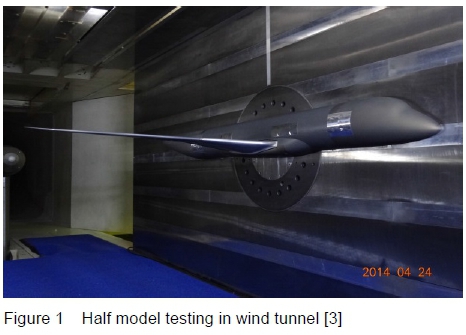
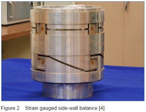
As an object (aircraft, missile, etc.) travels through air it experiences aerodynamic forces and moments. In order to determine these aerodynamic forces and moments, experimental tests are conducted on scaled models in a wind tunnel (figure 1). Traditionally, the instrument relied upon to provide accurate aerodynamic load test data is a strain gauged wind tunnel balance as shown in figure 2. Over the years the design of strain gauged balances has remained largely unchanged.
Some of the problems associated with using strain gauges on wind tunnel balances include susceptibility to electromagnetic interference (EMI), complexity in design because of the need to measure surface strain, high manufacturing costs and lengthy manufacturing lead times [2]. With the continual drive to improve static force accuracy, to increase resolution, increase stiffness and improve thermal stability, research into the use of alternative strain sensing technologies has been pursued.
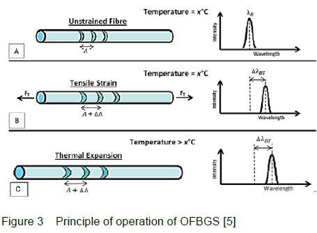
One attractive technology that has shown potential is the optical fibre Bragg grating sensor (OFBG). OFBGs operate on the principle of reflecting light of a certain wavelength whilst transmitting all other wavelengths. A Bragg grating is a set of narrow bands (gratings) of altered refractive index in the glass inner core of the fibre. These are created using a laser beam. The reflected wavelength is determined by the distance between the Bragg gratings. Therefore, by altering the distance between the gratings, the reflected wavelength is altered. A simple method of altering the distance between the gratings is to stretch the fibre. A strain in the fibre can be created by attaching the fibre at two discrete points inside a balance. When the balance is loaded relative displacement between these two points will occur due to deformation of the balance. Therefore any change in wavelength reflected from the Bragg grating is directly related to the force applied to the balance.
Thermal expansion also causes a shift in reflected wavelength. The principle of operation of Bragg gratings, including thermal expansion, is illustrated in figure 3.
The ability of OFBGs to measure the relative displacement between two points inside the structure of a balance is useful. It allows high strain levels to be created and measured without excessively increasing the stress levels within the balance structure. The use of sensors measuring the relative displacement of points internal to a balance, (as opposed to sensors measuring material surface-strain at points in the balance structure), requires a fundamentally different approach to balance design.
This paper presents results of an investigation into, and evaluation of, the potential advantages associated with the use of OFBG sensors in wind tunnel balances. The advantages of using OFBGs in a balance are:
• EMI immunity
• Low manufacturing cost
• Reduced material stress
• High stiffness
• Improved sensitivity
• Comparable resolution
The evaluation of OFBGs as alternative sensors for use in wind tunnel balances was done through the design, manufacture and testing of a wind tunnel side-wall, (or halfmodel) balance.
2 Design
The examination of currently accepted balance design philosophies, which are primarily based on the employment of strain gauges, has led to the conclusion that no single factor including new balance design, improved or alternative sensor technologies, the use of alternative materials or improved calibration methods, applied in isolation, will provide a significant improvement in balance data quality. It is suggested that the development of significantly improved balances must incorporate improvements in all of these factors [1].
Traditional balance design philosophy hinges on the principle of increasing the surface strain of the balance material at the location of a strain gauge in order to achieve a desirable strain gauge sensor output. The new design philosophy relies on the displacement between points in the structure of the balance in order to create a strain in an OFBG sensor. This must be done whilst maintaining a low stress level in the balance. This is achieved by using the two-groove method developed by Pieterse [1] and illustrated in figure 4.
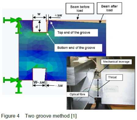
An understanding of the two-groove method requires a basic understanding of the principle of operation of OFBG sensors. The two-groove method allows for mechanical strain amplification, design and manufacturing simplification, and a mechanism for thermal correction.
An existing strain gauged SWB is illustrated in figure 5. The alternative OFBG balance design is shown in figure 6. The positions of the OFBGs used to measure normal force are shown by the red lines and side force are shown by the green lines respectively.
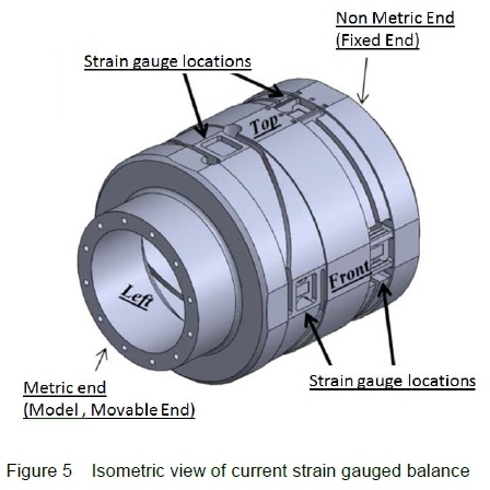
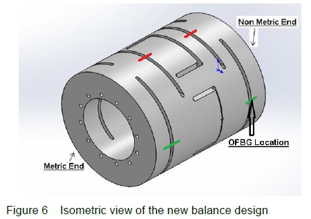
It can be seen that the OFBG balance requires less complex machining and is a simpler design when compared to an existing strain gauge balance. This results in a balance with reduced manufacturing costs and lead times.
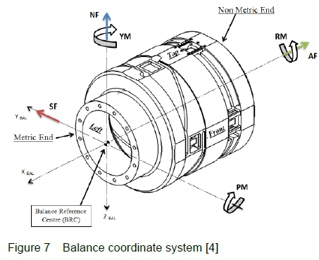
Figure 7 shows the force and moment convention that was used to calibrate the strain gauged balance.
Improved balance sensitivity, (output units per unit applied load), is made possible by using the two-groove technique [1] to amplify the OFBG output signal to a desirable level. Increased sensitivity provides the option of designing a stiffer balance. A stiffer balance, in turn, results in a more linear response. Reduction in stress levels allows for the evaluation of different balance materials that exhibit more desirable properties. This will result in a balance with low thermal expansion and provide greater thermal stability compared to the current high strength balance materials. Further research into the feasibility of these lower strength materials is being pursued but will not be specifically addressed in this paper.
3 OFBG Balance Design
Numerous factors need to be taken into consideration when designing a wind tunnel balance. In a side-wall balance, special attention has to be given to the following:
• Balance geometry and design loads
• Balance groove design
• Design for minimum interactions
• Sensor resolution
• Safety factor of 3
• Compatible with wind tunnel mounting features
3.1 Balance Geometry and Applied Loads
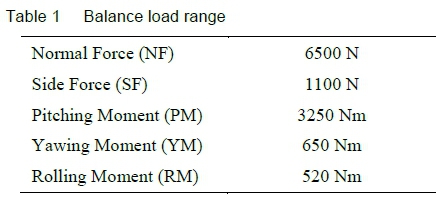
In order for the balance to be compatible with the calibration rig and wind tunnel, the outer diameter and length, as well as the metric and non-metric interfaces of the balance are prescribed. Additionally, the load capacity of the balance was prescribed. The required load ranges for each of the components are given in table 1.
3.2 Groove Design
The response of a fibre, (pre-tensioned across a groove), is dependent on the change of width (deformation) of the groove when the balance is loaded. The balance structural design is therefore focussed on the change of width of the various grooves or slots machined into the balance. The displacement measured by the fibre is the result of variations in the fibre tension, which causes a change in the spacing of the Bragg gratings, and hence a shift in reflected wavelength. The fibre response is therefore largely dependent, inter alia, on the length, width and depth of the groove. The fibre strain under full balance load has to be of a sufficient magnitude to obtain the maximum allowable wavelength shift but not large enough to result in fibre failure.
It is desirable that the fibre operates within its elastic region at all times. Figure 8 shows that the limit of the elastic region is around 5% elongation which translates to 50 000 με.
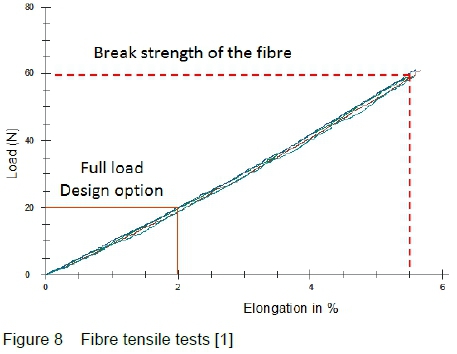
The fibres cannot measure compressive strains, they therefore need to be pre-tensioned. A pre-tension strain value of 10 000 με was considered to be adequate for this design. A higher pre-tension strain value can be used but was avoided so as to simplify the pre-tensioning (installation) process.
Using FEM, the length and depth of each groove could be determined such that when a given design load is applied, the strain in the fibre is greater than 1 000 με, whilst ensuring that the strain due to a combination of loads does not exceed 10 000με. This allows for sufficient resolution to be obtained whilst not causing the fibre to lose tension or to fail under tension. A minimum groove width is determined by the length of an OFBG grating, (5 mm). A balance groove width of 7 mm was selected. This allowed for a fibre installation (placement) tolerance of ±1 mm.
3.3 Fibre response and interactions
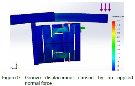
The balance was designed iteratively using the Cosmos Works® FEM and Solid Works® solid modelling software. From the FEM analysis, the relative nodal displacements on either side of each groove were used to estimate the strain in each fibre under different balance loading conditions. A typical simulation output is shown in figure 9 where the two fibre positions B1 and B3 are illustrated by the red lines.
The notation used to help in the identification of each of the OFBG sensors is shown in figure 10. A1 to A4 are used for SF deformation and grooves B1 to B4 are used for NF deformation.
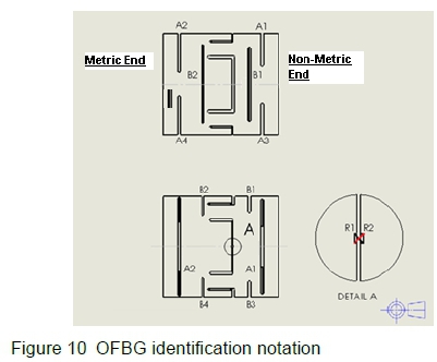
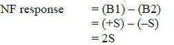
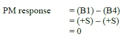
Figure 11 shows the deformations of the various spanning grooves for an applied NF. For an applied NF the output from the fibres spanning the grooves, B1 and B2, can be subtracted. Similarly, for an applied pitching moment the two OFBG responses from B1 and B4 can be subtracted. An increasing OFBG output, (increase in groove width), is indicated using a "+S", and decreasing OFBG output, (closing of the groove), by a "-S".
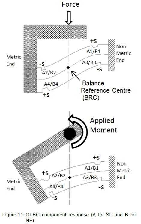
Combining two grooves to obtain an output results in isolation of components and a reduction in thermal effects.
When a force (NF or SF) is applied the output from the grooves can be subtracted thus cancelling the unwanted responses (PM or YM) as illustrated in figure 11.
Thus when a normal force is applied to the balance the normal force response is:
The pitching moment response for the applied normal force is:
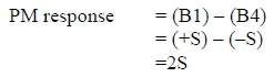
When a pitching moment is applied to the balance the pitching moment response is:
The NF response for the applied pitching moment is: NF response = (B1) - (B2)
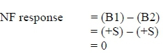
The selected sensor response combinations for the five balance components are given in table 2.
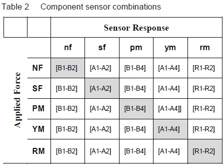
3.4 Interactions
Interactions are defined as the influence on all the sensors when a force or pitching moment is applied to the balance. Consider table 2, if a normal force (NF) is applied to the balance, the normal force sensor response (nf) is defined to be the difference of the response from fibre B1 and B2, and the pitching moment (pm) response is defined to be B1-B4. Fibres for side force A1, A2, A3 and A4 lie on the neutral axis and should ideally produce zero response. Because of the orientation of R1 and R2, (45 degrees), the difference between R1 and R2 should also produce a response of zero. The predicted fibre strains from the FEM analysis for each of the maximum design loads, combined according to table 2, are given in table 3.
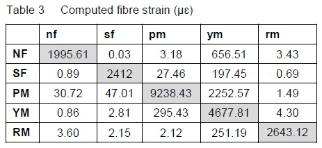
Fibre strain can be converted to an equivalent shift in wavelength using the ratio [1]:
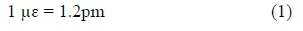
The fibre strain data given in table 3 is presented in terms of wavelength shift in table 4.
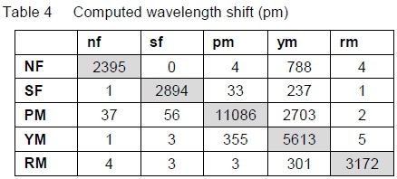
Balance component interactions indirectly degrade the balance performance. Large interactions decrease the percentage of allowable strain in the fibre which is available for the primary component. This is due to the fibre already being strained by the non-associated loads. Minimising component interactions is therefore a primary goal in balance design.
To understand the magnitude of the interactions, the computed wavelength shifts as shown in table 4 are converted to a percentage of full scale as shown in table 5.
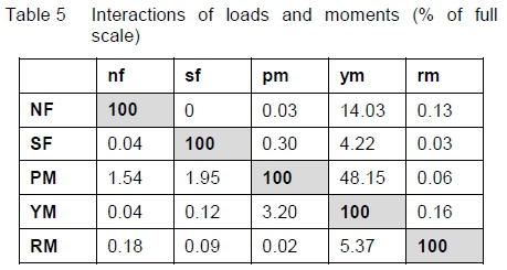
From table 5 it can be seen that when a normal force is applied to the balance the response (nf) is taken as 100%. By applying the normal force an unwanted response is induced in the yawing moment sensor which shows as a 14.03% interaction with respect to the full scale yawing moment response.
Seven of the interactions are less than 0.1% and these interactions are the ideal design outcomes. Five of the interactions are between 0.1% and 0.3% of the applied loads and are acceptable for this design. Five are between 1% and 10% which is workable if they are repeatable [6]. The worst interactions are yawing moment (24.38%) due to an applied normal force, and yawing moment (48.15%) due to an applied pitching moment. Possible reasons for these high values are firstly the relatively high loads in the NF plane compared to those in the SF plane, and secondly the manner in which the tensioned fibres move off the neutral axis as a result of balance deformation.
3.5 Resolution
The resolution of the OFBG is dependent on the smallest resolvable wavelength increment of the integrator being used. The integrator that will be used has a resolution of ±1 pm (digital). Since there are two OFBGs used per net output response, the smallest resolvable increment is taken to be ±2 pm (1.66 με).
To evaluate the resolution in comparison with what can be achieved with a strain gauge balance, it is convenient to express the value as a percentage of the response at full loading as shown in table 6.
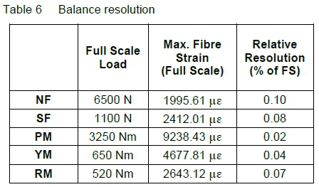
A typical strain gauged balance has maximum values of 6 000 to 10 000 μν with a resolution ±1 μν giving a relative resolution of 0.01%. This is however an optimum value. Full scale values of as low as 1 000 μν are often seen, particularly in components such as axial force and rolling moment. A typical high value for relative resolution on a strain gauged balance would then be of the order of 0.1%.
The resolution given in table 6 can be seen to be in a similar range to that which is expected from strain gauge balances having a better than ±1 με resolution. In practice the resolution of strain gauge balances is greater than ±1 με and may as high as ±3 or ±4 με. The potential resolution of an optical fibre balance is therefore equal to, or better than, a typical strain gauge balance.
3.6 Balance Material Stress
The material stress in the balance caused by an applied load, or due to combinations of applied loads, must be less than three times the allowable stress for the balance material. This safety factor is required to ensure that the balance does not fail in service. Maintenance of this factor of safety has the additional advantages of both ensuring a linear balance characteristic and of improved fatigue life. The stresses caused by a given load on the balance are determined using FEM with material properties for 17-4PH stainless steel. Maximum von Mises stress levels are shown in table 7.
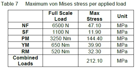
A typical maximum material stress used in strain gauged balance design is in the region of 600 MPa with a safety factor of three. From this the optical fibre side-wall balance configuration has a maximum design stress with all combined loads of 212.1 MPa.
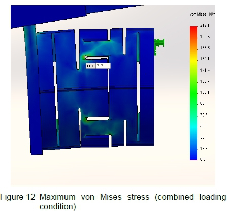
The prototype is to be manufactured from 17-4PH stainless steel, which has an allowable stress of 1240 MPa. Maintaining a safety factor of three requires that the maximum stress in the balance be less than 413.33 MPa. The maximum stress occurs when all loads are applied simultaneously. The maximum stress of the current design is 212.10 MPa. This is indicated in figure 12. This gives a safety factor of 5.85 which is above the required safety factor of three.
3.7 Manufacturing
A manufacturing lead time for this balance is estimated at 60 working days whereas a strain gauge balance can take up to 410 days [2].
Because of the relatively simple geometry of the optical fibre side-wall balance, (figure 6), no specialised machining equipment is needed. In the case of the strain gauged side-wall balance, (figure 5), highly specialised manufacturing equipment and expertise is needed to manufacture the intricate geometry.
Because of the specialised manufacturing equipment and machining expertise required, the cost of manufacture of the optical fibre side-wall balance will be considerably less than the strain gauged side-wall balance.
4 Conclusion
This design indicates that application of the new design philosophy to produce an alternative optical fibre side-wall balance offers significant advantages. The balance can be designed to have the high local deformations in selected regions whilst maintaining low stress levels in the balance structure. From the results, the optical fibre side-wall balance concept can be justified by immunity to EMI, an acceptable signal-to-noise ratio, relative resolution, and low material stress levels. The design also demonstrates both a simplification and reduction in manufacturing cost and lead times.
The manufacture of a prototype of the balance is required in order to demonstrate functionality and to verify the theoretical results. Some aspects such as the unexpectedly high interactions of PM and the yawing moment response need to be better understood.
Acknowledgements
This works was funded by the Council for Scientific and Industrial Research (CSIR) in South Africa.
References
1. Pieterse FF, The Application of Optical Fibre Bragg Grating Sensors to an Internal Wind Tunnel Balance, PhD Thesis, University of Johannesburg, Johannesburg, South Africa, 2010. [ Links ]
2. Burns DE, Williams QE, Phillips DB and Commo SA, Review of Potential Wind Tunnel Balance Technologies, NASA Internal Document https://ntrs.nasa.gov/archive/nasa/casi.ntrs.nasa.gov/20160009123.pdf, 2016.
3. Photo from November Test Series, courtesy of the Council for Scientific and Industrial Research (CSIR) in South Africa 2017.
4. Burger A, Evaluation of Optical Fibre Bragg Grating Sensors on a Side-wall Wind Tunnel Balance, MEng dissertation, University of Johannesburg, Johannesburg, South Africa, 2014. [ Links ]
5. De Ponte HJ, The Design and Development of a Plate form Type Wind Tunnel Balance with Optical Fibre Bragg Grating Sensors, MEng dissertation, University of Johannesburg, Johannesburg, South Africa, 2015. [ Links ]
6. Bidgood PM, Development of the 014mm-HARMS-3t Balance, 7th International Symposium on Strain-Gauge Balances, Williamsburg, VA, USA, 2010.
Received 18 November 2016,
Rrevised form 8 August 2017
Accepted 10 August 2017

