


Services on Demand
Article
 English (pdf)
 Article in xml format
 Article references
Indicators

Related links
-
 Cited by Google
 -
 Similars in Google
Share

 Permalink
R&D Journal
On-line version ISSN 2309-8988
Print version ISSN 0257-9669
R&D j. (Matieland, Online) vol.33 Stellenbosch, Cape Town 2017
A computational tool for predicting hybrid rocket motor performance
B. GenevieveI; J.F. Pitot de la BeaujardiereII; M.J. BrooksIII
IDiscipline of Mechanical Engineering. University of KwaZulu-Natal, Durban, South Africa. E-mail: berns.genev@gmail.com
IIDiscipline of Mechanical Engineering, University of KwaZulu-Natal, Durban, South Africa. E-mail: pitot@ukzn.ac.za
IIISAIMechE Member. Discipline of Mechanical Engineering, University of KwaZulu-Natal, Durban, South Africa. E-mail: brooks@ukzn.ac.za
ABSTRACT
A model is described to aid in the design of hybrid rockets and in the prediction of motor performance, specifically with respect to the University of KwaZulu-Natal's Phoenix-1A vehicle. The Hybrid Rocket Performance Code (HRPC), programmed in MATLAB, is segregated into two individual models: i) a preliminary motor design code to analyse and design hybrid rocket motors, and ii) a predictive motor performance code to compute the instantaneous motor performance for a targeted burn time. The predictive motor performance code is based on a one-dimensional unsteady gas flow model through the nozzle and, on a zero-dimensional model of the combustion chamber capturing only the filling and emptying dynamics. The zero-dimensional model is linked to a self-pressurising delivery tank model obtainedfrom literature to simulate the changes in physicochemical properties of nitrous oxide in the tank. HRPC is coupled with NASA-CEA equilibrium chemistry program to determine the thermodynamic properties of the combustion products necessary for solving the governing ordinary differential equations. As such, different propellant combinations can be analysed for motor performances. The HRPC application is validated against hot-fire test data of Phoenix-lA's PV-1 flight motor and against reported performance data from the literature.
Additional keywords: Hybrid rocket propulsion, nitrous oxide, paraffin-wax, computational model
Nomenclature Roman
a regression rate ballistic coefficient
Ab burnt surface area [m2]
Ainj injector orifice cross-sectional area [m2]
Ap grain port cross-sectional area [m2]
cp specific heat capacity at constant pressure [J/(kg.K)]
cv specific heat capacity at constant volume [J/(kg.K)]
c* characteristic velocity [m/s]
Cd discharge coefficient
Cf thrust coefficient
molar heat capacity at constant pressure [J/(mol.K)]
molar heat capacity at constant volume [J/(mol.K)]
g gravitational acceleration [m/s2]
G mass flux rate [kg/(m2.s)]
h specific enthalpy [J/kg]
H enthalpy [J]
molar enthalpy [J/mol]
Isp specific impulse [s]
k specific heat ratio
kc chamber specific heat ratio
Lg grain length [m]
m mass [kg]
m mass flow rate [kg/s]
Mfc fuel mass storage in chamber [kg]
Moc oxidiser mass storage in chamber [kg]
MW molecular mass [kg/mol]
n number of moles [mol], regression rate bal coefficient
η number of moles of fluid flow rate [mol/s]
Ninj number of injector orifices
Np number of grain ports
P pressure [Pa]
pa atmospheric pressure [Pa]
Pc chamber pressure [Pa]
Pe nozzle exit pressure [Pa]
Plosses pressure drop in feed line [Pa]
saturated vapour pressure of nitrous oxide [Pa]
Q heat transfer energy [J]
f regression rate [m/s]
fcl classical regression rate [m/s]
Rp port radius [m]
Ru universal gas constant [J/(mol.K)]
T temperature [K]
u specific internal energy [J/kg]
U internal energy [J]
molar internal energy [J/mol]
ve nozzle exit velocity [m/s]
V volume [m3]
V molar volume [m3/mol] W work done [J]
x axial port distance [m]
Greek
β blowing coefficient
molar heat of vaporisation [J/mol]
Sr nozzle expansion ratio
ηeff combustion efficiency
λ nozzle gas flow correction factor
μ combustion gas viscosity [Pa.s]
ρ density [kg/m3]
Subscripts
a atmospheric
c combustion chamber
e exit
f fuel
g gas, grain
in inflow
l liquid
noz nozzle
out outflow
ox oxidiser
ox,d oxidiser discharge
ox,l liquid oxidiser
ox,v vapour oxidiser
sp,v supercharge gas
t total, throat
T tank
v vapour
1 Introduction
The hybrid rocket offers attractive advantages over solid and liquid variants in university-based research programmes. These include safety, throttling capability, propellant versatility, design simplicity and lower fabrication cost [1,2]. It is classified as a chemical rocket due to the required energy being generated from the combustion process of the propellants, which are stored in two distinct states before undergoing the chemical reaction. In the conventional and most used hybrid rocket motors, the oxidiser and fuel are in the liquid and solid phases, respectively.
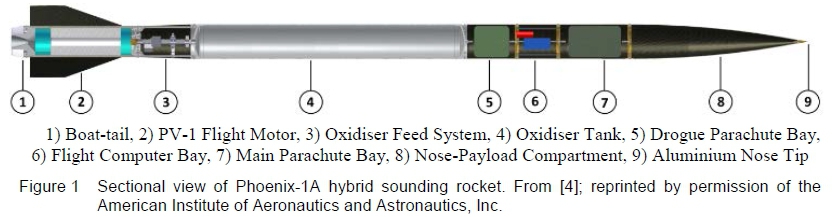
In 2010, the University of KwaZulu-Natal (UKZN) initiated the Phoenix Hybrid Sounding Rocket Programme to address the lack of an indigenous sub-orbital launch capability and meet the demands of the South African and African scientific research communities. The programme's long-term objective is to develop a series of sub-orbital hybrid sounding rockets for customers engaged in atmospheric and space physics research, starting with a first low-altitude demonstrator, Phoenix-1A, which was designed to deliver a 1 kg payload to 10 km altitude. A paraffin-wax/nitrous oxide propellant combination was selected as the propulsion system. To date, the progress in UKZN's Programme includes the design and static tests of the PL-1 lab-scale motor [3], design and static test of the PV-1 flight motor [3,4,5], development of a Hybrid Rocket Performance Simulation (HYROPS) model [6], development of vehicle airframe and internal components [4,5,6], and the launch of Phoenix-1A [7]. The Phoenix-1A rocket is depicted in the cross-sectional view in figure 1.
The vehicle's airframe consists of an ogive nose cone with aluminium tip, drogue and main parachute bays, a flight computer bay, four stabilizing fins, a boat-tail, and a tapered inter-stage section for encasing the feed system. The combustion chamber casing and oxidiser tank were manufactured from 6082-T6 aluminium alloy. The motor essentially consists of the chamber casing, a grade 431 stainless steel torispherical injector bulkhead and nozzle retainer, a fine grain graphite nozzle, and a fuel grain cartridge, as the core of the propulsion system. The rocket's four trapezoidal fins, machined from 6082-T6 aluminium alloy, are located in the stainless steel rail structures secured to the combustion chamber. The fin arrangement is canted at an angle of 0.5° to the motor axis. All airframe components were fabricated from carbon fibre epoxy composite. The total length of the rocket, from the nose tip to the boat-tail, is 4.55 m and the fully fuelled mass is 95 kg.
This paper describes the development of a simulation tool called the Hybrid Rocket Performance Code (HRPC) to model the propulsion mechanism of hybrid rocket motors, and reports the successful hot-fire test of the PV-1 flight motor. In particular, the current work consists of the modelling of the nitrous oxide self-pressurising delivery system, regression rate modelling of paraffin-based fuels, and modelling of the gas dynamics within the combustion chamber and nozzle. HRPC is an in-house software tool originally intended for use in the design process of PV-1 flight motor. This initiative resulted from a lack of software tools available for hybrid motors, specifically, for the performance prediction of nitrous oxide/paraffin-wax propellant combinations. Different mathematical models can be found in the literature for the modelling of a self-pressurising delivery system [8,9], regression rate [10,11,12,13], and gas flow dynamics in the combustion chamber [14,15,16], but these focus mainly on individual sub-components of hybrid rocket propulsion systems. The coupling of the three sub-components is critical for simulating the overall motor performance.
In HPRC they are merged to numerically solve for the power-plant theoretical performance. In addition, HRPC permits useful analysis and development of a propulsion system for targeted design specifications, that is, designing the fuel grain and nozzle configurations by providing the engine parameters such as targeted thrust, chamber pressure, oxidiser-to-fuel ratio, and oxidiser/fuel combination. The overall goal is to produce a comprehensive software tool for the preliminary design and performance prediction of hybrid rocket motors.
2 Hybrid Rocket Propulsion System Modelling
2.1 Description of the hybrid propulsion system physical and chemical models
The physicochemical process of a classical hybrid propulsion system can be defined by the three key control volumes shown in figure 2, where each one models the change in thermodynamic properties of the contained propellant or combustion products. These sub-systems are solved for their critical unknown parameters, leading to the solution of rocket-propulsion fundamental formulae and, hence, to the prediction of general motor performance.
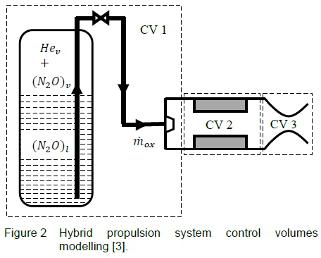
In this study, control volume 1 (CV1) models the nitrous oxide delivery system supercharged with inert helium gas. The delivery system is a blowdown process due to the self-pressurising characteristic of nitrous oxide and the omission of pumps in the feed line. The blowdown process of the tank and the back pressure created in the combustion chamber determine the oxidiser mass flow rate through the injector. Control volume 2 (CV2) deals with the multiphysics reaction of the propellants, specifically the pyrolysis of the solid-fuel grain caused by a diffusion flame zone in the main stream and the combustion process of the reactants. Control volume 3 (CV3) computes the gas flow dynamics in the nozzle to determine the rocket thrust and related parameters such as specific impulse and characteristic velocity. The solution of CV3, and hence motor performance, is highly dependent on the output effects of CV1 and CV2. The NASA-CEA equilibrium chemistry code [17] is employed to obtain the thermodynamic properties of the gaseous products in CV2 and CV3 during the burn period.
2.2 Oxidiser tank pressurisation and blowdown process
The self-pressurising delivery system in this research consists of two-phase liquid-vapour nitrous oxide that is volatile at room temperature, and a non-condensable single-phase helium vapour mixture. The insoluble non-reactive helium gas assists the blowdown process by supercharging nitrous oxide above its ambient vapour pressure and reinforcing flow to the combustion chamber. In addition, the system is more stable as helium gas increases the ignition energy of nitrous oxide hence minimizing the risk of uncontrolled thermal decomposition.
In CV1, figure 3, the properties of the nitrous oxide depend on the equilibrium state of the delivery system and vary as the tank is discharged during the rocket's powered phase of flight. The thermodynamic state variation of nitrous oxide is dependent on the oxidiser tank environmental temperature and on the fluid flowing out of CV1. As nitrous oxide is forced out of the tank, the internal energy of the tank contents decreases with time. During this period, liquid nitrous oxide at the interface evaporates to equilibrate the liquid/vapour system which results in a loss of thermal energy and, consequently, reduces the tank pressure. This causes a noticeable decrease in nitrous oxide flow rate and, thus, motor thrust during burn time, provided that the feed system is not throttled. By evaluating the mass and temperature variations of the nitrous oxide in the tank, the change in the system's pressure can be predicted. The following mathematical model is based on the work of Fernandez [18] who developed two numerical models for a nitrous oxide self-pressurising delivery system. The first model is based on the ideal gas law and, the second model utilises a non-ideal equation-of-state. In this paper, the ideal method is adopted but with some adaptations to the solution structure for the unknown parameters.
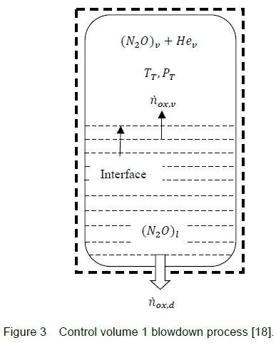
Considering a tank partially filled with two-phase liquid-vapour nitrous oxide and single-phase helium vapour as the initial conditions of CV1, figure 3. By applying mass and energy conservation to the system, the decay in tank pressure can be computed for the initial nitrous oxide mass and temperature parameters. The following assumptions were employed in the model:
1. The mono-propellant remains in thermodynamic equilibrium throughout the blowdown process.
2. The gas component of the system obeys the ideal gas law.
3. The oxidiser tank wall is assumed to be adiabatic and in thermal equilibrium with the propellant.
4. The liquid phase consists of pure nitrous oxide whereas the gas phase is a mixture of nitrous oxide vapour and helium gas.
5. Evaporation at the liquid-vapour interface is not influenced by boiling phenomena.
6. Potential and kinetic energies of the propellant are neglected.
7. The gravitational head in the tank is negligible for both static and flight tests.
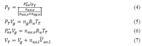
The main differential equations obtained from applying the conservation of mass and energy principles to the blowdown process are defined below. These are numerically solved to determine the tank pressure, temperature, and the number of moles of the liquid and vapour nitrous oxide inside the tank. By the conservation of mass, the change in number of moles of the whole system is given by:

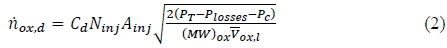
The conventional mass flow rate equation through an orifice, transformed into molar form is given by:
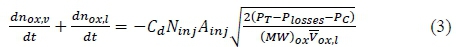
The rate of change of nitrous oxide mass inside the tank is determined by equating equation 2 to 1:
Equation 6 below is obtained by substituting Raoult's law, equation 4, into the ideal gas law, equation 5:
where Vg is the gas phase (nitrous oxide vapour + gaseous helium) volume. Substituting equation 6 into 7, and differentiating with respect to time gives:
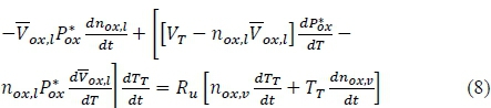
An energy balance is taken for the entire CV1 with the following simplifications: heat exchange to the environment is neglected, Q = 0, there is no moving boundary work done on the system, W = 0, and the tank wall and the propellant are assumed to be in thermal equilibrium. With these assumptions:

Expanding equation 9 gives:
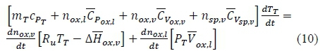
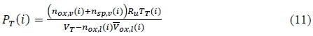
where the heat of vaporisation of nitrous oxide is defined as the difference between its vapour and liquid phase enthalpies,  Equations 3, 8, and 10 are solved simultaneously for the three unknown time derivatives: number of moles of the liquid nitrous oxide, dnox,ι /dt, number of moles of the vapour nitrous oxide, dnoxv /dt, and the tank temperature, dTT/dt. A fourth order Runge-Kutta numerical approach is employed in the HRPC to integrate the three unknowns and solve for n01Cii(i+1), nox,v(i+1) and Tr(i+1) at each time step, i. The tank pressure solution is determined by:
To provide closure of the system, the change in specific/molar heat capacities at constant pressure (nitrous oxide, helium, and oxidiser tank material), the heat of vaporisation and molar specific volume of the liquid nitrous oxide, and the vapour pressure of the nitrous oxide are computed using the temperature-dependent formulae provided in Perry and Green [3,19].
2.3 Solid-fuel regression rate modelling
The regression rate of a solid fuel, also known as the burning rate or pyrolysis process, determines the degree of oxidiser-to-fuel mixture composition in the combustion chamber. The two most recognised regression rate theories are the classical diffusion limited theory by Marxman et al. [10] and the non-classical liquefying entrainment mass-transfer theory by Karabeyoglu et al. [11,12]. One common characteristic of both theories is the strong dependency of solid-fuel burning rate on oxidiser flow rate. However, the non-classical regression rate theory is based on solid fuels that liquefy as heat is transferred to the inner surface such as paraffin wax. These fuels form an unstable liquefied layer over the burning surface which is entrained in the form of droplets into the stream. The regression rate is enhanced by the entrainment mass transfer of the grain.
In this study, the solid-fuel regression rate is modelled by the semi-empirical expression [1] obtained from the reduction of the classical diffusion limited theory developed by Marxman et al. [10]. In the classical diffusion limited theory, the regression rate of a solid-fuel grain is dependent on the oxidiser mass flux and heat transfer to the grain:

The diffusion limited theory can be simplified into a semi-empirical expression, whereby, the blowing coefficient β, combustion gas viscosity μ, and fuel density ρ/, are condensed into one factor, a. The reduced power law expression is defined as:

The three ballistic coefficients are determined by static hot-fire experiments for different propellant combinations. In the literature, the axial position exponent m tends to be much less than 1, hence the space variation can be ignored m=0 [1]. In addition, the total mass flux, Gt=Gox+G/, is replaced by the oxidiser mass flux, 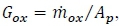 as the fuel mass entrained into the combustion zone compared to the burnt fuel in the mean flow is relatively small. Thus, the semi-empirical regression rate expression is reduced to:

The fuel mass flow rate is a function of the oxidiser flow and the rate at which the solid fuel regresses. For cylindrical ports, the burnt surface area is computed as Ab = 2nNpRpLg and the fuel mass flow rate by 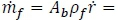
 .
.
2.4 Zero-dimensional combustion chamber gas model
The transient behaviour of the hybrid combustion mechanism is modelled by the filling/emptying gas dynamics of the combustion chamber. A zero-dimensional model is applied to CV2 to capture the change in thermodynamic properties of the fluid flow over the burn time with no spatial change through the combustion chamber. Referring to figure 4, the conservation of mass and energy are applied to the single node control volume 2 to analyse the change in chamber pressure, oxidiser-to-fuel ratio, and other combustion gas properties. The following assumptions were implemented to simplify the model:
1. The combustion gas product behaves as a perfect gas.
2. The propellant mass stored in CV2 is non-uniform due to the change in chamber volume and gaseous mass flow out of the nozzle.
3. Uniform regression rate is assumed across the fuel grain.
4. There is no heat transfer through the chamber wall.
5. There is no pressure drop across the chamber.
6. The spatial change in thermodynamic gas properties is not modelled.
7. There is no oxidiser vaporisation lag and no fuel grain gasification lag.
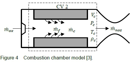
Applying the 1st law of thermodynamics:

where Qc= 0 (zero heat exchange with the environment), Wc= -Pc(dVc/dt) (work done by pressure forces), h=cpT (specific enthalpy) and dmc/dt = mox+ rhf - mnoz(mass stored in the chamber). Using the ideal gas law, and differentiating with respect to time, the change in combustion enthalpy dHc/dt is given as:
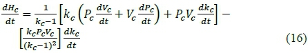
The time derivative of the chamber pressure is modelled from the enthalpy expression of a homogeneous system:  assuming
  and using equations 15 and 16:
In the above, a one-sided differencing technique is used to solve for the change in specific heat ratio of the combustion:  and the instantaneous change in chamber volume is
  The change in port radius, and oxidiser and fuel mass storages are defined as:
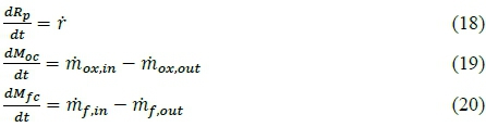
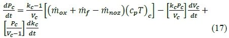
Equations 17 to 20 are integrated for their respective state variables of chamber pressure, port radius, oxidiser mass storage, and fuel mass storage. The HRPC employs a fourth order Runge-Kutta time marching scheme to solve for the state vectors. The term (rhox+ riif - mnoz) in equation 17 determines the filling or emptying of the combustion chamber. The NASA-CEA equilibrium chemistry code is used to obtain the combustion gas properties such as the flame temperature Tc, specific heat ratio kc, and specific heat capacity at constant pressure cPc, for the chamber pressure and oxidiser-to-fuel ratio at each time step.
3 Hybrid Rocket Performance Code
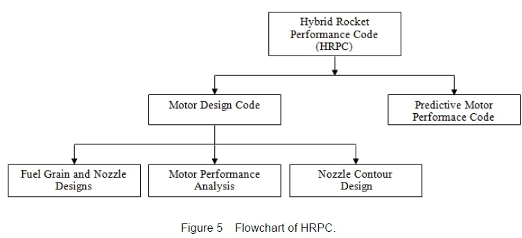
Using the equations given in Section 2, a hybrid rocket performance model was developed to enable both the design and theoretical performance prediction of the Phoenix-1A rocket with its propellant combination of paraffin wax and nitrous oxide. The model can also be used to analyse other oxidiser/fuel combinations and so has more universal application. It is divided into two distinct codes, namely a preliminary motor design code (HRPC Motor Design Code) and a predictive motor performance code (HRPC Predictive Motor Performance Code) as shown in figure 5.
The design of a hybrid propulsion system is achieved through the HPRC Motor Design Code. The code computes, among other parameters, the optimum nozzle expansion ratio, nozzle critical pressure ratios, dimensions of the fuel grain and oxidiser mass flow rate for a targeted thrust, the chamber and atmospheric pressures, and the oxidiser-to-fuel ratio. Moreover, the code has the capability to plot the converging-diverging contour for a bell-shaped or conical-shaped nozzle. These two-dimensional coordinates can be imported into CAD software. The HRPC Predictive Motor Performance Code is utilized to predict the instantaneous motor performances with the draining of the oxidiser tank and the physical change of the solid-fuel grain. Critical outputs from the Motor Design Code are used as inputs to the predictive motor performance model.
3.1 NASA-CEA
The Hybrid Rocket Performance Code is linked to the combustion and theoretical rocket performance sub-models of NASA-CEA to obtain essential parameters such as the thermodynamic properties, characteristic velocity, and specific impulse of a propellant combination. The inputs to the NASA-CEA application include the oxidiser/fuel properties, oxidiser-to-fuel ratio, chamber pressure, and nozzle expansion ratio or inverse pressure ratio. HRPC creates an input file with the problem fully stated, runs the NASA-CEA application, and saves the calculated output data into lookup tables.
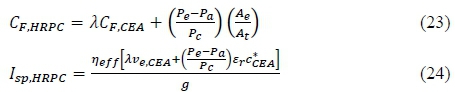
Some post-processing of the NASA-CEA output data is required to successfully obtain the motor performance. The ideal gas exit velocity of NASA-CEA Ve,cEA must be corrected for the divergence nozzle exit angle as described in equations 21, 23, and 24. A combustion efficiency is introduced to the characteristic velocity  in equation 22 to model the combustion performance of the propellants.
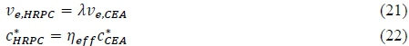
Since the NASA-CEA rocket performance sub-model assumes that the nozzle gas flow is perfectly expanded (third critical point condition), the difference in exit and atmospheric pressures must be accommodated for by adding the pressure-thrust term to the thrust coefficient Cf,cea and specific impulse Isp,CEA.
3.2 HRPC data processing and numerical solution
The Predictive Motor Performance Code is a numerical model that couples and solves the three key control volumes of the hybrid propulsion system (described in Section 2) to predict the performance variation with burn time. Some of the calculated output parameters from HPRC Motor Design Code are fed into HRPC as essential inputs. The code computes the governing equations of rocket propulsion until it reaches the maximum pre-set burn time or until other variable set-points are met.
Prior to running the Predictive Motor Performance Code, lookup tables are created through NASA-CEA for the specified propellant combination, nozzle expansion ratio, and nozzle flow composition. Key features of the code include defining a fuel propellant of two compositions, defining the molecular formula and enthalpy of the fuel and oxidiser if absent in NASA-CEA's thermodynamic library, and running the 'only' and 'omit' subroutines of NASA-CEA.
The main input parameters to the code are the oxidiser flow method, fuel grain dimensions and motor specifications. The application can model five types of oxidiser flow methods:
1. Constant oxidiser mass flow rate throughout the burn.
2. Constant oxidiser mass flow rate with throttling sequence employed.
3. Nitrous oxide self-pressurising delivery system.
4. Constant oxidiser tank pressure throughout the burn.
5. Polynomial curve fit employed for the oxidiser tank pressure (function of time).
The oxidiser mass flow rate is calculated at each time step for the selected oxidiser flow method, oxidiser parameters, feed system inputs and pressure difference (including expected pressure drop in feed line). The solid-fuel regression rate is calculated using equation 14 with the appropriate user supplied ballistic coefficients for the motor configuration. Required inputs for the computation of the fuel mass flow rate are the fuel grain length, number of cylindrical ports (up to 10 ports), and initial port diameter. The grain outside diameter, determined from the Motor Design Code, is used as one of the stopping criteria for the numerical model.
The Predictive Motor Performance Code determines the type of flow through the nozzle (subsonic, shock wave, or supersonic) by comparing the instantaneous nozzle pressure ratio with its critical points obtained from the Motor Design Code. The motor performance is computed using the rocket propulsion fundamental equations for the current flow regime (subsonic, shock wave, or supersonic). The changes in physical and chemical properties in CV2 provide solutions for the chamber pressure derivative dPc/dt, and for CV1, the time derivatives of the number of moles of liquid nitrous oxide dnoxl/dt, the number of moles of vapour nitrous oxide dn0XiV/dt, and the tank temperature dTT/dt. The computed dependent variables are fed back to different sub-models for the next time-step solution. Output files containing the instantaneous parameters and average rocket motor performances are created for inspection at the end of the simulation. In addition, the code produces a series of graphs and a two-dimensional representation of the burnt fuel grain.
3.3 HRPC validation
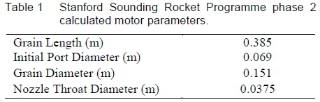
The HRPC Predictive Motor Performance Code was validated against reported hot-fire motor test data and performance modelling data. Notably, it was compared with the performance modelling data of the second phase of Stanford University's Stanford Sounding Rocket Programme [20], which is advantageous since that vehicle's motor is not dissimilar to Phoenix-1A's in scale and utilizes an identical oxidiser. Most of the critical propulsion system parameters were reported in the literature excluding the grain dimensions and nozzle geometry, which, for the purposes of comparison, were calculated based on the cross-sectional view of the combustion chamber, given initial oxidiser mass flow rate and mass flux and expansion ratio. They are given in table 1 below.
The following assumptions were made for the HPRC model:
1. The regression rate ballistic coefficient, a, for pure paraffin wax/nitrous oxide combination was increased by 10% to 0.1705X10⁻³ to account for the higher regression rate of the aluminised paraffin-wax fuel [21]. Note, for a pure paraffin wax/nitrous oxide combination, ballistic coefficients were as follows: a = 0.155>10-3 and n = 0.5 (f in m/s and Gox in kg/(m2s)) [21].
2. A fixed atmospheric pressure was assumed at sea-level.
3. Combustion efficiency of 95%.
4. Bell-shaped nozzle with 0.985 correction factor.
5. The feed system was designed for an initial chamber pressure of 31><105 Pa, with a discharged coefficient of 0.8, an orifice diameter of 0.002 m, the number of orifices 15, and a pressure drop of 8>105 Pa in the feed line.
Figure 6 shows the difference between the HRPC-derived prediction of Stanford motor performance and the reported motor thrust data. The thrust profiles follow a similar trend. That is, peak thrust is achieved initially, followed by a gradual decrease in thrust with tank pressure, and a shift in oxidiser-to-fuel ratio. The tail-down stage at the end of the burn is due to the liquid-vapour phase change of the oxidiser. It is noted that the peak thrust obtained in HRPC is higher than the predicted 5000 N from the model of Karabeyoglu et al. [20]. This may be due to the difference in the assumed initial conditions and transient combustion modelling of the two models which includes the filling dynamics of the chamber.
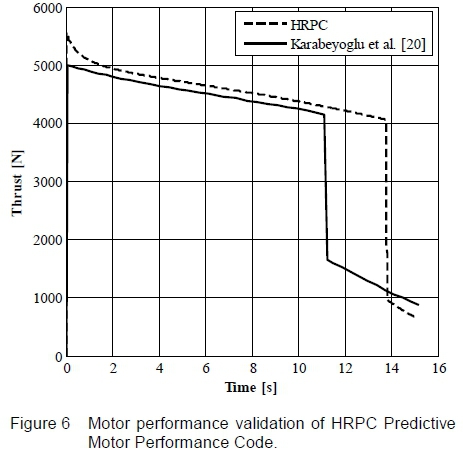
The main discrepancy between the thrust profiles is in the predicted consumption of liquid nitrous oxide. This phase-change is reported to occur at approximately 11.2 s in their model, whereas, HPRC predicts it at 13.8 s. This difference may be due to the uncertainty in the loaded nitrous oxide mass and/or a higher oxidiser mass flow rate obtained in their model due to the difference in tank and chamber pressures. Moreover, initial assumptions in the HRPC run may have contributed to the difference in predicted performances. In particular, the regression rate ballistic coefficient for aluminised paraffin-wax/nitrous oxide was approximated as it was not reported in the paper. In addition, their predictive code models the flight dynamics of the rocket, including changes in atmospheric pressure, whereas a fixed value is used for the atmospheric pressure in HRPC. Another possible source of deviation is the determination process of the fuel grain dimensions and nozzle geometry. Overall, though, good agreement was obtained between the models.
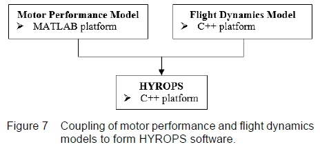
3.4 Implementation into the UKZN HYROPS software
The HRPC application is integrated with UKZN's Hybrid Rocket Performance Simulator (HYROPS) software that is a hybrid rocket trajectory simulation tool intended to predict the sub-orbital flight performance of a generic multi-stage hybrid sounding rocket, as shown in figure 7. The HYROPS software tool links the hybrid motor performance model to the flight dynamics model developed by Chowdhury [6]. It is programmed in Microsoft Visual C++ programming language.
The HYROPS software tool numerically solves the core six-degree-of-freedom rocket flight dynamics equations, given initial conditions, a vehicle inertia model, a vehicle propulsion system model, a vehicle aerodynamic model, a model for the earth's gravitation and atmosphere, and a model of the vehicle's recovery system. The gravitational and geodetic models include effects for the rotation and shape of the earth whilst the altitude-dependent atmospheric model is also used to simulate density changes and winds. The motor performance outputs such as the momentum-thrust history, nozzle exit pressure history, oxidiser and fuel consumption histories, and fuel volumes and dimensions are used in a fully coupled manner in simulation time to model the high fidelity operation of a hybrid rocket motor on a sounding rocket. The self-pressurising delivery system model from HRPC application is used to compute the residual oxidiser mass and volume at each time step which in turn determines the length of the column of oxidiser in the tank. This change in oxidiser characteristics is coupled to the vehicle structural model of HYROPS to simulate the variation in the vehicle mass distribution and centre of gravity. Similarly, the motor fuel masses and dimensions are coupled to the HYROPS vehicle structural model while the thrust vector is determined by the nozzle exit pressure and momentum-thrust outputs, and the drop in atmospheric pressure as the vehicle ascends.
A graphical user interface is incorporated in the HYROPS software tool to enable the input of details related to the vehicle structure, geometry, and propulsion system. Outputs from the application are available in animated 3D visualizations including a variety of graphical and tabular formats. The full functionalities and features of HYROPS software tool are described by Chowdhury [6].
4 Phoenix-IA Static and Flight Tests
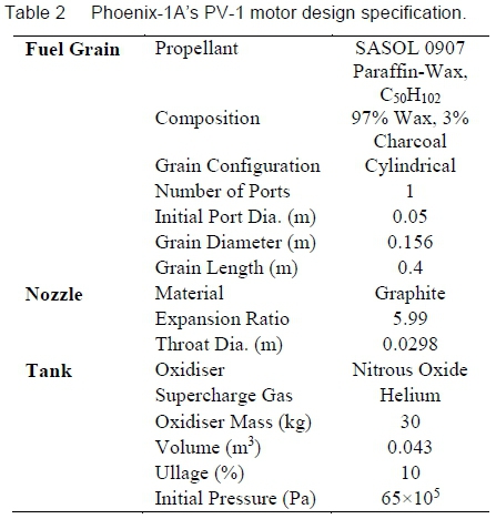
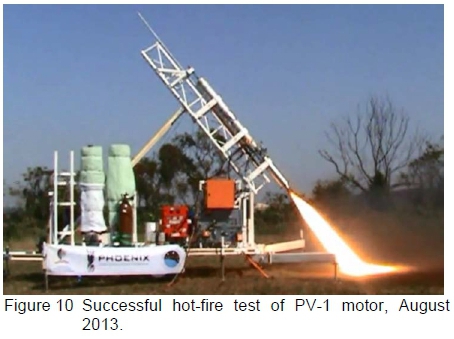
Phoenix-1A's PV-1 motor design specification is given in table 2. The motor was successfully static test-fired on UKZN's purpose-built Mobile Rocket Launch Platform (MRLP) in August 2013. The MRLP contains all the required electrical and mechanical ground support equipment to remotely control static tests and launches via a LabVIEW application [3].
The test results are shown in figures 8 and 9, together with their respective theoretical curves simulated in HRPC. The inputs to the HPRC model are: i) loaded nitrous oxide of 20.8 kg, ii) loaded helium gas of 0.022 kg to raise the initial tank pressure to 65><105 Pa, iii) fuel-grain density of 930 kg/m3, iv) ballistic coefficients a and n of 0.155>10-3 and 0.5, respectively, for f in m/s and Gox in kg/(m2s) [21], v) assumed injector discharged coefficient of 0.6, vi) assumed feed system pressure drop of 10>105 Pa (excluding the injector pressure drop), vii) assumed combustion efficiency of 0.9, viii) bell-shaped nozzle correction factor of 0.985, ix) atmospheric pressure of 1.0132>105 Pa, and x) equilibrium nozzle gas flow analysis (NASA-CEA input).
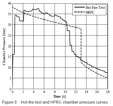
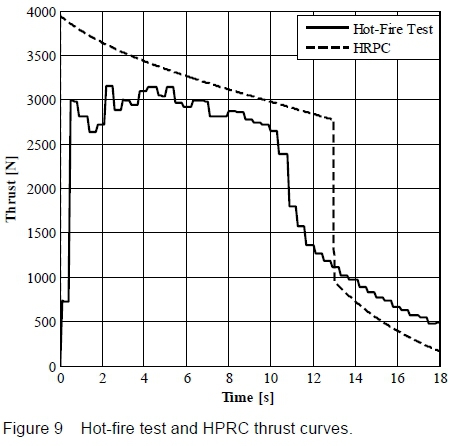
Referring to the experimental curves, a maximum thrust of 3156.9 N was recorded at 2.2 s corresponding to a chamber pressure of 36.8>105 Pa. Steady-state was sustained for approximately 10 s until the liquid-phase nitrous oxide was depleted. The significant decrease in chamber pressure and thrust coincides with the change in phase of nitrous oxide from liquid to gas. To compare the theoretical model and the hot-fire test data, the HRPC application was run for a feed system pressure drop of 10>105 Pa, which differs from the designed/calculated 6.5>105 Pa, to account for the higher pressure drop in the hot-fire test. For the same reason, the theoretical injector discharged coefficient of 0.8 was amended to an assumed value of 0.6. It can be seen that the theoretical chamber pressure is lower than the hot-fire test data, probably due to the simplified zero-dimensional model of control volume 2. The experimental chamber pressure curve is measured at the pre-combustion chamber which is essentially being compared with HRPC post-combustion chamber pressure. Although the pressure drop through a relatively short fuel-grain is minor, a one-dimensional model should be employed in HRPC to fully capture the spatial change in chamber pressure. Similarly to figure 6, HRPC modelled a prolonged liquid-phase nitrous oxide flow compared to the test data which is a limitation of the ideal gas theory employed in the blowdown model. Another source of error may be the assumed burning rate ballistic coefficients [21]. In general, the theoretical and experimental curves matched fairly well considering the possible range of errors.
Figure 10 shows the successful test and indicates the manner in which the oxidiser tank and PV-1 motor are secured onto the gantry inclined at a 60° angle (video footage [22]).
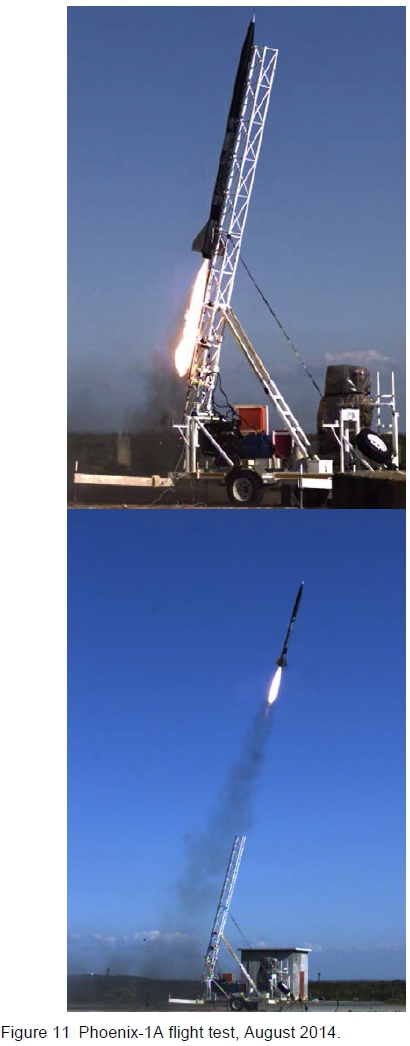
Following the successful static test, Phoenix-1A demonstrator rocket was launched in 2014 from the Denel Overberg Test Range (OTR) in South Africa [7]. Due to severe nozzle damage sustained shortly after ignition the rocket reached an apogee of 2.5 km, significantly lower than the predicted apogee of 6 km for the given oxidiser load on board. It is likely that a hard start at ignition may have caused the nozzle damage, although no pressure sensors were flown on the vehicle to confirm this. Post-flight analysis of the Phoenix-1A test is the subject of another research paper. Photographs of the vehicle leaving its rail are given in figure 11.
5 Conclusions
The objective of this research was to develop a performance simulation tool for the design and analysis of the Phoenix-1A hybrid rocket demonstrator. The approach is sufficiently general to allow for the modelling of other nitrous oxide and paraffin wax motors, as well as a range of different oxidiser/fuel combinations.
The performance model rests on classifying a motor into three control volumes: i) the nitrous oxide self-pressurising delivery system (CV1), 2) zero-dimensional gas dynamics model of the combustion chamber including the multiphysics reaction and regression rate theory (CV2), and 3) the one-dimensional gas dynamic flow through the rocket nozzle (CV3).
Two computational sub-models of the Hybrid Rocket Performance Code (HRPC) are described for: i) general hybrid motor design (HRPC Motor Design Code), and ii) predicting the instantaneous motor performance (HRPC Predictive Motor Performance Code). Specifically, the Motor Design Code is used for sizing a hybrid motor including its fuel grain and nozzle dimensions, whereas, the Predictive Motor Performance Code models actual instantaneous performance of the motor by solving the unknown equations of the three control volumes with a 4th order Runge-Kutta numerical method. The two codes extract essential thermodynamic properties from the NASA-CEA equilibrium chemistry code. The hot-fire test data of Phoenix-1A's PV-1 motor are compared with the HRPC application and reasonably good agreement was obtained. In addition, the HRPC application was compared with a predictive model from the Stanford University Sounding Rocket Programme, again with reasonably good agreement.
The Phoenix-1A vehicle development programme has come to an end with the primary objectives reached. These included the hot-fire tests of lab-scale motors and the full-scale PV-1 flight motor, the development of a Hybrid Rocket Performance Simulation (HYROPS) software tool, the integration of the vehicle's airframe and internal components with the PV-1 propulsion system, and the launch of Phoenix-1A vehicle from the Denel Overberg Test Range (OTR), near Cape Agulhas, South Africa. Both HYROPS and HRPC are now in use for the development of the second vehicle, Phoenix-IB, which has a target apogee of 10 km.
Acknowledgements
The authors wish to thank Denel Overberg Test Range, SASOL, Armscor, the South African Air Force, DST, the CSIR, the National Research Foundation, and the South African National Space Agency. We are grateful to Seffat Chowdhury, Fiona Leverone, Kirsty Veale, and Udil Balmogim for their contributions to this research.
References
1. Sutton GP and Biblar O, Rocket Propulsion Elements, 8th ed., John Wiley & Sons, New Jersey, 2010.
2. Davydenko NA, Gollender RG, Gubertov AM, Mironov VV and Volkov NN, Hybrid Rocket Engines: The Benefits and Prospects, Aerospace Science and Technology, 2007, 11(1), 55-60. [ Links ]
3. Genevieve B, Development of a Hybrid Sounding Rocket Motor, MScEng thesis, Discipline of Mechanical Engineering, University of KwaZulu-Natal, South Africa, 2013. [ Links ]
4. Pitot de la Beaujardiere JF, Brooks MJ, chowdhury SM, Genevieve B and Roberts LW, The Phoenix Hybrid Sounding Rocket Program: A Progress Report, Proceedings: 47th AIAA/ASME/SAE/ASEE Joint Propulsion conference, San Diego, CA, 2011.
5. Genevieve B, chowdhury SM, Brooks MJ, Pitot de la Beaujardiere JF, Veale K and Roberts LW, The Phoenix Sounding Rocket Program: A Progress Report 2012, Proceedings: 48th Annual AIAA/ASME/SAE/ASEE Joint Propulsion Conference, Atlanta, GA, 2012.
6. Chowdhury SM, Design and Performance Simulation of a Hybrid Sounding Rocket, MScEng thesis, Discipline of Mechanical Engineering, University of KwaZulu-Natal, South Africa, 2013. [ Links ]
7. Genevieve B, Pitot de la Beaujardiere JF, Brooks MJ, Chowdhury SM, Veale K, Leverone F, Balmogim U and Mawbey R, Flight Test of the Phoenix-1A Hybrid Rocket, Proceedings: 51st AIAA/SAE/ASEE Joint Propulsion Conference, Orlando, Florida, 2015.
8. Whitmore SA and Chandler SN, Engineering Model for Self-pressurizing Saturated-N2O-propellant Feed System, AIAA Journal Propulsion and Power, 2010, 26(4), 706-714. [ Links ]
9. Zimmerman JE, Waxman BS, Cantwell BJ and Zilliac GG, Review and Evaluation of Models for Self- pressurizing Propellant Tank Dynamics, Proceedings: 49th AIAA/ASME/SAE/ASEE Joint Propulsion Conference, San Jose, CA, 2013.
10. Marxman GA, Wooldridge CE and Muzzy RJ, Fundamentals of Hybrid Boundary Layer Combustion, Progress in Aeronautics and Astronautics, 1964, 15, 485-522. [ Links ]
11. Karabeyoglu MA, Altman D and Cantwell BJ, Combustion of Liquefying Hybrid Propellants: Part 1, General Theory, Journal of Propulsion and Power, 2002, 18(3), 610-620. [ Links ]
12. Karabeyoglu MA and Cantwell BJ, Combustion of Liquefying Hybrid Propellants: Part 2, Stability of Liquid Films, Journal of Propulsion and Power, 2002, 18(3), 621-630. [ Links ]
13. Barato F, Bellomo N, Lazzarin M, Moretto F, Bettella A and Pavarin D, Numerical Modelling of Paraffin-based Fuels Behaviour, Proceedings: 48th AIAA/ASME/SAE/ASEE Joint Propulsion Conference, Atlanta, GA, 2012.
14. Chelaru TV and Mingireanu F, Hybrid Rocket Engine, Theoretical Model and Experiment, Acta Astronautica, 2011, 68(11-12), 1891-1902. [ Links ]
15. Guobiao C, Hao Z, Dalin R and Hui T, Optimal Design of Hybrid Rotor Motor Powered Vehicle for Suborbital Flight, Aerospace Science and Technology, 2013, 25(1), 114-124. [ Links ]
16. Barato F, Bellomo N, Faenza M, Lazzarin M, Bettella A and Pavarin D, Numerical Model to Analyse Transient Behaviour and Instabilities on Hybrid Rocket Motors, Journal of Propulsion and Power, 2015, 31(2), 643-653. [ Links ]
17. Gordon S and McBride BJ, Computer Program for Calculation of Complex Chemical Equilibrium Compositions and Applications, NASA RP-1311, 1994.
18. Fernandez MM, Propellant Tank Pressurization Modelling for a Hybrid Rocket, MScEng thesis, Rochester Institute of Technology, USA, 2009. [ Links ]
19. Perry RH and Green DW, Perry's Chemical Engineers' Handbook, 8th ed., McGraw-Hill, New York, 2007.
20. Karabeyoglu MA, Zilliac G, Castellucci P, Urbanczyk P, Stevens J, Inalhan G, Cantwell BJ and Field M, Development of High-burning-rate Hybrid-rocket-fuel Flight Demonstrators, Proceedings: 39th AIAA/ASME/ASEE Joint Propulsion Conference, Huntsville, Al, 2003.
21. McCormick A, Hultgren E, Lichtman M, Smith J, Sneed R and Azimi S, Design, Optimization, and Launch of a 3" Diameter N2O/aluminised Paraffin Rocket, Proceedings: 41st AIAA/ASME/SAE/ASEE Joint Propulsion Conference, Tucson, Arizona, 2005.
22. ASReG UKZN, UKZN's Phoenix-1A Hybrid Rocket Motor Static Hot Fire Test 1, http://www.youtube.com/watch?v=Fvpw4bz90Ts.
Received 30 March 2017
Revised form 3 August 2017
Accepted 18 August 2017

