


Services on Demand
Article
 English (pdf)
 Article in xml format
 Article references
Indicators

Related links
-
 Cited by Google
 -
 Similars in Google
Share

 Permalink
Journal of the Southern African Institute of Mining and Metallurgy
On-line version ISSN 2411-9717
Print version ISSN 2225-6253
J. S. Afr. Inst. Min. Metall. vol.124 n.3 Johannesburg Mar. 2024
http://dx.doi.org/10.17159/2411-9717/3292/2024
COMPUTATIONAL MODELLING PAPERS
Incompressible versus compressible fluid flow models: A case study on furnace tap-hole lancing
M.W. ErweeI, II; Q.G. ReynoldsIII, IV; J.H. ZietsmanI, V
IUniversity of Pretoria, Pretoria, South Africa
IISamancor Chrome Ltd, Sandton, South Africa
IIIMintek, Randburg, South Africa
IVStellenbosch University, Stellenbosch, South Africa
VEx Mente Ltd, Pretoria, South Africa
SYNOPSIS
Pyrometallurgical furnaces, essential for metal extraction, operate at temperatures exceeding 1600°C and represent complex multiphase systems that challenge direct industrial research. Multiphysics models play a key role in shedding light on their intricate behaviours, supporting the refinement of design and operational strategies. Integral to the operation are the tap-holes, which facilitate the removal of molten products and are routinely opened by lancing, a process comparable to the use of a cutting torch, where high temperatures result from oxygen reacting with an iron lance. When the lance pierces the clay, oxygen gas enters the furnace, which could influence the behaviour of the molten material inside. In this work, a multiphase fluid flow model was used to investigate bulk flow dynamics, with a focus on the effects of the lancing process on the inside of the furnace, immediately behind the tap-hole. Incompressible and compressible multiphase fluid solvers were used and compared with respect their performance - the intention was to assess whether using a compressible solver would yield a different solution to the incompressible one. It was concluded that there are negligible disparities in bulk fluid flow behaviour between the solvers for the case studies examined, indicating that solver selection might be less consequential for certain aspects of oxygen lancing.
Keywords: tap-hole, lancing, modelling, multiphase fluid flow.
Introduction
Background
High temperature processing of ores to produce metals, alloys, mattes, and slags is carried out in pyrometallurgical furnaces. The furnaces vary significantly in design, but all have one aspect in common: material needs to be removed from the vessel at certain stages of the production process. In most cases, the molten material is removed through a tap-hole.
DC open bath furnaces are used for the production of ferrochrome, titanium slag, ferronickel, and steel (Jones, 2014). Raw material is usually charged continuously into DC furnaces, with a direct current electric arc acting as an intense, focused heat source. The energy intensity of the process is such that the melting and reactions occur rapidly compared to other furnace heating methods. The molten slag and alloy accumulate inside the furnace and are tapped at regular intervals.
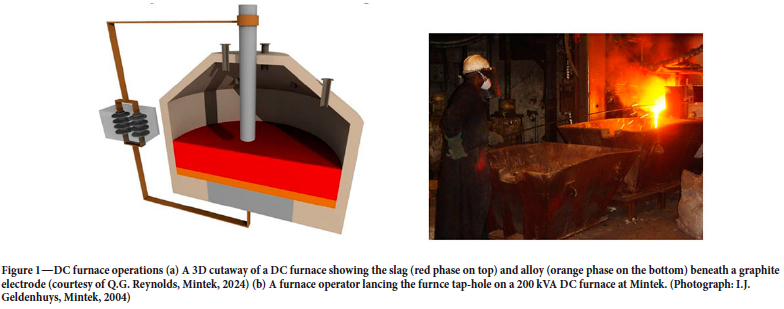
An example of a DC furnace is shown in Figure 1a.
A furnace tap-hole undergoes periodic closing and opening. Closing is achieved by sealing the tap-hole with refractory clay which expands and hardens, creating a plug to block material flow.
To tap the furnace, this refractory plug is removed. This can be achieved mechanically, thermally, or through a combination of both. Mechanical removal involves drilling into the hardened plug, while thermal removal melts the material away using an oxygen lance.
Oxygen lancing is used only when absolutely necessary, for example, in blast furnace ironmaking and ilmenite smelting (Nelson and Hundermark, 2016; Mgenge, and Steenkamp, 2014), while in other processes such as ferrochrome production, a combination of drilling and oxygen lancing for each tap is commonplace (Nelson and Hundermark, 2016; Lindstad, 2018). In a platinum and Ni smelter industry survey, it was found that about 36% of these furnaces employ lancing as the primary means of opening the tap-hole (Nolet, 2014). In some platinum smelters, it is common for slag and matte tap-holes to be opened using oxygen lancing almost exclusively (van Beek et al., 2014).
Lancing furnace tap-holes is an aggressive process and, if not done with care, can result in significant damage to the refractory lining and tap-hole of a furnace, in addition to potentially harming the furnace operator. An example of an expert furnace tapper lancing a tap-hole is shown in Figure 1b.
The lances used for opening the tap-hole are made of carbon steel tubes with varying diameters. Lance designs vary, but operate in the same way. Pure oxygen is charged through the tube at high flow rates (approximately 100-600 Nm3/h)(Trefimet, 20171). The tip of the lance is ignited by using a spark or flame. The burning of the lance is due to the continuous oxidation of iron in the steel tube with the release of intense, focused heat at the tip. This heat is used to melt the hardened clay inside the tap-hole.
Not all the oxygen is consumed by the burning of the lance, with up to two thirds bypassing through the tip of the lance (Morales, Morales, and Nunes, 2018).
DC furnaces can be sensitive to operate and care is required to maintain and run them effectively. Compared to, for example, submerged arc furnaces (SAFs), bulk reaction dynamics in DC furnaces is rapid, i.e. changes in process parameters often manifest within a very short time and as such continuous monitoring as well as the prevention of process disturbances are essential (Geldenhuis, 2017).
Recently, the authors conducted a series of studies (Erwee, Reynolds, and Zietsman, 2016, 2023; Erwee et al., 2019) to investigate the impact of lancing furnace tap-holes using multiphase fluid flow and thermochemical modelling. The focus of these studies was specifically on the case in which oxygen bypasses the lance tip and comes into contact with the molten process material. Limited literature exists on this topic, because the problem cannot be directly studied in a furnace; yet, evidence of damage is often observed in the tap-hole region when furnaces are down for maintenance.
Modelling offers an alternative way of unpacking the problem, but does pose its own challenges due to the complex nature thereof.
Impetus for and scope of this study
The authors have studied the possible effects of lancing from different angles (Erwee, Reynolds, and Zietsman, 2016, 2023; Erwee et al., 2019), specifically for open-bath smelting processes such as DC ferrochrome smelting, trying to establish the best framework to answer two main questions:
> How would short bursts of oxygen from the lance influence the molten process material? Some subquestions that come to mind:
- Is the slag-alloy interface disturbed in any significant way? (this work)
- Would upset conditions in a furnace be exacerbated by lancing? (future work).
> Can modelling offer some insight as to what extent the process could be influenced?
- Could one use the results from modelling to better quantify the effect of lancing? (this work)
- Could the results from the modelling work be used with other models (e.g. thermochemical models) to better understand refractory wear? (future work).
In previous studies (Erwee, Reynolds, and Zietsman, 2016, 2023; Erwee et al., 2019), the authors mainly used an incompressible multiphase fluid flow solver in the OpenFOAM open source platform. The choice of solver and approach is explained in previous work, but it was necessary to do a sub-study in which a compressible solver was used to capture any potential flaws in the assumptions made in the incompressible solver.
The reason for testing a compressible solver is the fact that unlike alloys and slags in furnaces, gases such as oxygen, which would enter through the lance, are compressible.
Many compressible-flow solvers are available in commercial and open source CFD tools; however, finding accurate values for material properties with temperature can prove to be a problem in pyrometallurgy, which means that the effort required to achieve sufficiently accurate models increases. The question the authors had was how much this would change any of the possible answers when compared to the incompressible case?
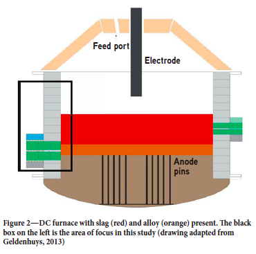
In this paper, the focus is specifically on a case where the alloy tap-hole is lanced while slag is still present in the furnace (see Figure 2).
Governing equations, modelling framework, and solvers
The governing equations for the multiphase fluid flow problem were solved using the open-source framework OpenFOAM*v2212 (OpenFOAM, 2024), using two standard solvers: an incompressible multiphase solver, multiphaseInterFoam, and the compressible version of the solver, compressibleMultiphaseInterFoam. To track the interfaces between the phases, the volume of fluid method is used (Hirt and Nichols, 1981}.
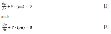
For both solvers, the equations for the conservation of momentum and mass are solved:
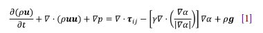
where p is the density of the fluid, u is the velocity, p is the pressure, Tij the viscous shear tensor, and a the phase fraction of each phase (gas, slag, and alloy).
The pressure term, p, refers to the static pressure minus the quasi-hydrostatic2 pressure, pgh. In the incompressible solver, an arbitrary reference value can be chosen for p, while in the compressible solver, this value is calculated from the equation of state.
where:
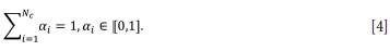
The bulk density and viscosity of each cell are scaled linearly by the volume fraction of each phase that occupies the cell.
In the case of the incompressible solver, the density of each phase is assumed to be constant, which simplifies the aforementioned equations.
Although most alloys and slags are considered incompressible fluids, gases such as oxygen and carbon monoxide are considered compressible, and the density of these gases is a function of both pressure and temperature (via an equation of state chosen by a user). In the compressible version of the solver, the effects of temperature on the density of each phase can be accounted for by solving an additional energy equation (see Equation [5]). There is a compressible component added to the incompressible component in the pressure equation in compressibleMultiphaselnterFoam (not shown here).
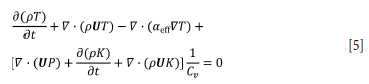
where T is the temperature, aeff represents the effective thermal diffusivity, and K is a representation of the flow kinetic energy.
In both solvers, the assumption is made that viscosity and interfacial tension are constant. In reality, there would be changes in these values as a function of temperature, composition, presence of surfactants, etc. However, values for these two parameters also come with a degree of uncertainty, since they are difficult to measure. The sensitivity of bulk flow in and around the tap-hole region to these parameters is a topic for future study.
Computational domain, meshing strategy, and computing resources used
Computational domain
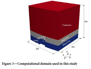
The area of interest in this case study is the alloy tap-hole area of the furnace (see black box3 in Figure 2). An enlarged version of this area in three dimensions is shown in Figure 3. The domain is a 1/6th wedge of a furnace with a diameter of 12 m, the same as in a previous study (Erwee, Reynolds, and Zietsman, 2023).
Meshing strategy
The computational domain is quite large. To fully resolve flow, quite a fine mesh is required, typically a maximum element size of 2.5 mm was specified in the final mesh used. However, meshing the entire domain at that resolution would be computationally expensive. To overcome this problem, a preliminary simulation was performed on a coarse mesh, followed by refinement in the areas where flow was dominant. This approach has proven to be successful in the past (Reynolds et al., 2019; Erwee, Reynolds, and Zietsman, 2023). Although adaptive mesh refinement could be implemented, it could be more computationally expensive. Coarse meshes were typically in the order of 500 000 elements, with finer meshes at 3.2 million elements. An example of a coarse and a fine mesh is shown in Figures 4a and 4b, respectively. Meshes were generated using cfMesh (cfMesh, 2022)).
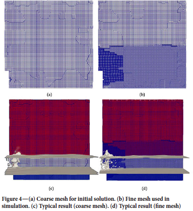
Note that the visualizations shown in the figures are a slice through the middle of the three-dimensional domain (a plane in the y-direction).
Computing resources
To simulate 5 seconds of real time4 in a reasonable amount of time, it was necessary to use parallel computing resources. Computations were done at the NICIS Centre for High Performance Computing in Cape Town on 10 computing nodes, each equipped with Intel Xeon processors (2.6 GHz, 24 cores) and 128 GB RAM. The simulations took between 25 and 72 hours to complete. Post-processing was performed in ParaView version 5.11.0 (Hansen, and Johnson, 2005; Ayachit, 2015; Kitware, 2024) on a desktop computer equipped with a Ryzen 9 5950X CPU, 64GB RAM, and a NVidia GTX 4070 graphics card. It is interesting to note that, on average, the compressible solver did not take a significant amount of extra time over the incompressible one for simulations (often less than 20% more computing hours were required).
Basis for comparison and model assumptions
Basis for comparison
To test the idea that a compressible solver would yield a different result from an incompressible one for this particular problem, three case studies were performed. At the same time, a second idea was tested, i.e. the sensitivity of the compressible solver to a difference in gas inlet temperature was also performed.
Simulations were performed for a case where lancing is done in the alloy tap-hole, but some slag is still present in the furnace5. The authors concede that when conditions change significantly this assumption would need to be checked again. However, there are only a few typical configurations for this particular problem in an industrial environment.
Three cases were considered:
> Incompressible case 0, where parameters were fixed as per Table I
> Compressible case 1, where the values for the parameters were the same as in case 0, but an energy equation is solved. This case was considered to see whether there would be a different result from case 0
> Compressible case 2, where there is a 200K difference between the gas temperature at the inlet and the molten phases (alloy and slag) at the beginning of the simulation. This was to test the sensitivity of the solution in case 1 to temperature.
To compare solutions against each other, each field that was solved for and was common in each of the solvers was compared over 5 seconds of real-time simulated. Solutions were compared along each principal direction from the lance tip:
> In the x-direction: gas travelling from the tip of the lance towards the centre of the furnace
> In the y-direction: from the tip of the lance to each side of the domain, i.e. gas travelling along the wall of the furnace
> In the z-direction: gas travelling upwards through the slag to the freeboard of the furnace.
The following parameters are plotted for comparison:
> The time-averaged density (both as a visualization of a plane through the middle of the domain as well as a plot of the density in each direction). Since density and pressure are coupled, it is necessary to see whether any significant changes in density are observed
> The time-averaged pressure at the lance tip and away from it (as per first item)
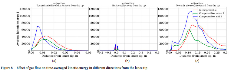
> The time-averaged kinetic energy, i.e.  , which serves to check whether there is any significant changes in energy dynamics between simulations.
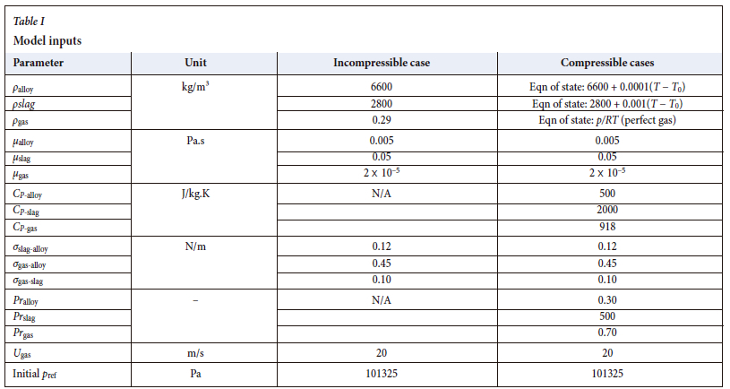
Model inputs and assumptions
For all simulations, the gas inlet velocity was set at 20 m/s, which is based on the diameter of the lance and the estimated flow rate of the gas bypassing the tip of the lance. Baseline values (incompressible case) for density, viscosity, and interfacial tension were taken from a ferrochrome system as documented in a previous publication (Erwee, Reynolds, and Zietsm, 2023. The Pr numbers6 for slag, alloy and gas were taken from Nelson and Hundermark (2016). Pr numbers are used in the compressible solver, together with the heat capacity, CP, for calculations related to the thermal diffusivity used in the energy equation (see Table I for details).
The importance of accurate materials properties should not be underestimated (Lopis et al., 2022), especially since these properties are difficult to obtain in pyrometallurgical systems. The authors wish to explicitly acknowledge that this will require further study; the effects of property variability are not part of the scope of this paper.
Case study results and discussion
Background to case study
The results of the OpenFOAM simulations were processed in ParaView for 5 seconds of real time using the temporal statistics filter. This filter computes simple statistics such as the average, standard deviation, minimum, and maximum values of all the different fields over time.
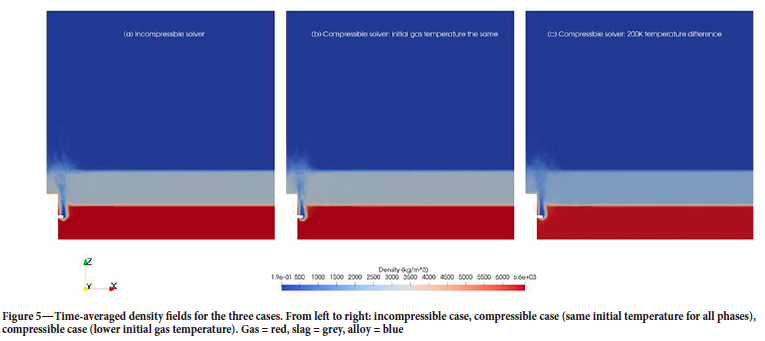
In all plots given, the results are presented in the order: incompressible case 0, compressible case 1 (injected gas at same initial temperature as other phases), and then compressible case 2 (a 200K difference between the gas and alloy/slag temperature at the start of the simulation).
Time-averaged density
A visual inspection of the density averaged over time provides a quick view of how each phase (gas, alloy, and slag) changes, on average, over the course of the simulation. Because the densities of the three phases are so distinctly different, the visualization is a reasonable representation of each phase fraction at the same time. In Figure 5, all three cases produce a very similar result. As the gas enters the alloy melt, it loses momentum in the direction of the lance and moves through both the alloy and the slag phasez, which is what one would expect due to the large density differences between the gas and the liquid phases.
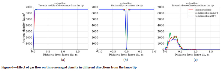
To study the differences in a more quantitative manner, the plots were compared in the three main directions from the lance tip. Gas does not penetrate deep into the melt, and most of the gas is concentrated at the tip of the lance. Interestingly, it can be seen that in the small region in front of the lance tip, the mixture has a density close to that of a gas-slag mixture (specifically see Figure 6c), i.e. the alloy is displaced and a slag-gas mixture circulates around the lance tip.
The most apparent differences, despite being small, are between the two compressible cases in the area in front of the lance tip. The difference in temperature of the gas and alloy results in a slightly different density between the cases. This is most noticeable in the z-direction, the main direction of gas flow. The incompressible solver solution falls between the two compressible solutions on average. In the x- and y-directions, there is virtually just alloy with variations in density only apparent to about a 0.1 m from the lance tip in these directions. The 'feet' on the two compressible cases can possibly be explained by the fact that close to the tip of the lance, the density is reflective of a mixture of gas and alloy.
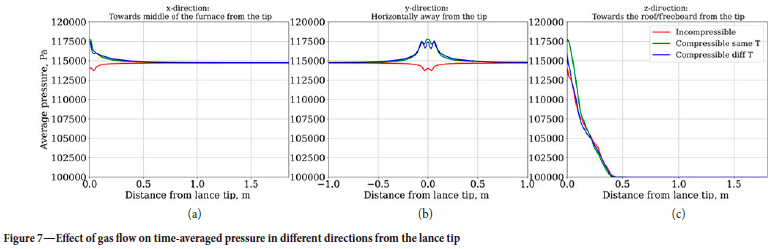
Time-averaged pressure
Plots of the average pressure follow much the same pattern as density. There is very little difference between the solutions (see Figure 7) close to the tip of the lance. In the case of the - and y-directions, pressure profiles converge to the pressure exerted by mostly the liquid alloy. Closer to the tip of the lance, the pressure profiles change somewhat due to the presence of gas. There is a distinct difference between the incompressible case and the two compressible ones in terms of the profile close to the lance tip. When post-processing the results for the compressible cases, it was observed that, within the first few time-steps (up to about 0.2 seconds), there is an initial spike in pressure, reflective of the temperature dependence of density and pressure in these calculations. The result is that the maximum pressure for the compressible cases (approx. 350 000 Pa) skews the average values used for the plot. When considering the effect that this has on the bulk fluid flow behaviour in the system, this difference becomes insignificant.
Time-averaged kinetic energy
When comparing the kinetic energy, the difference between the incompressible case which shares the same initial conditions as the compressible solver is also not noticeable, and the difference between the two compressible cases shows the effect of the difference in temperature more prominently (see Figure 8) in the z-direction.
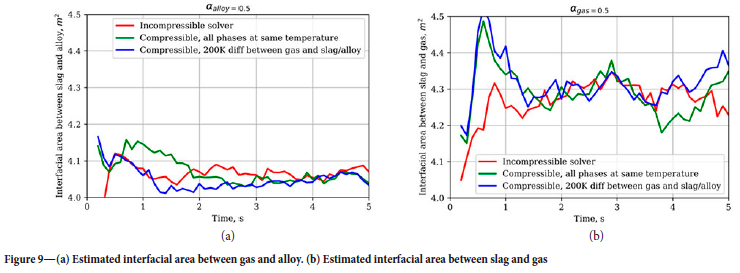
Estimated change in interfacial area
An estimate of the interfacial area between the slag and the alloy, as well as between the slag and the gas, was made over 5 seconds in real time. Such a calculation can be useful when, for example, mass transfer rates are of interest.
When comparing the incompressible case with the compressible case, the difference in the interfacial area looks large, but on average there is a 5% difference between the two solutions; the difference is simply exaggerated by the small range on the y-axis. Within the confines of an engineering estimate, this should not have a more significant impact on any design calculations. The same applies in this case to the difference in solutions between the two compressible cases. Note that the curves are less smooth due to the fact that the results for the simulation were only written out to files in 0.1 second intervals.
Conclusions and Recommendations
To consider the effect of the compressibility of gas when lancing into molten alloy in a full open bath furnace, and at the same time test how large the impact of a different gas inlet temperature would be, three case studies were performed using OpenFOAM as the calculation platform.
It was found that, for the properties of the same materials, there was no significant difference between the use of an incompressible fluid flow solver (multiphaselnterFoam) and its compressible counterpart (compressibleMultiPhaselnterFoam). Overall, both solutions are robust enough to capture the bulk flow dynamics in the particular cases considered and, as in the case of any simulation, depend on the quality of the inputs, especially materials properties. Despite the added complexity of the compressible solver, computational time was not as expensive as initially thought.
For the conditions assumed in the simulations, it was found that the interface between slag and alloy is disturbed in such a way that alloy can be displaced by a slag-gas mixture in front of the area where lancing occurs. A marginal shift in the overall interfacial area is also observed, concentrated at the tip of the lance.
Minor differences are apparent when there is a temperature difference between the gas at the tip of the lance entering the melt and the liquid phases, which was expected. When considering any future cases, it can be important to account for this, along with other materials properties, when studying the lancing problem in more detail.
Further studies will consider a more comprehensive parameter space search, especially changing the phase into which is lancing is done, different initial gas temperatures, as well as bath levels and depth of penetration of the lance, to double-check when a more complex solution is required.
Acknowledgements
This paper is published by permission of Mintek. The authors also thank the Centre for High Performance Computing (CHPC), which is part of the National Integrated Cyber Infrastructure System (NICIS), for making computing resources available for this research project.
References
Ayachit, U. 2015. The ParaView Guide: Updated for ParaView Version 4.3. Full color version. Edited by Lisa Avila. Kitware Inc., Clifton Park, NY.: Kitware Inc. ISBN: 978-1-930934-30-6. cfMesh. 2022. https://cfmesh.com/ [ Links ]
Erwee, M.W., Reynolds, Q.G., and Zietsman, J.H. 2016. Comparison of 2D and 3D computational multiphase fluid flow models of oxygen lancing of pyrometallurgical furnace tap-holes.'Journal of Metals, vol. 68, no. 6. pp. 1556-1562. http://link.springer.com/10.1007/s11837-016-1873-6 [ Links ]
Erwee, M.W., Reynolds, Q.G., and Zietsman, J.H. 2023. The effect of oxygen lancing into a furnace alloy tap-hole: A computational case study for an open-bath furnace. Journal of Metals, vol. 75, no. 1. pp. 248-253. https://link.springer.com/10.1007/s11837-022-05571-y [ Links ]
Erwee, M.W., Reynolds, Q.G., Zietsman, J.H., anD Bezuidenhout, P.J.A. 2019. Multiphase flow modelling of lancing of furnace tap-holes: validation of multiphase flow simulated in OpenFOAM". Journal of the Southern African Institute of Mining and Metallurgy, vol. 119, no. 6. https://www.saimm.co.za/Journal/v119n06p551.pdf. [ Links ]
Geldenhuys, I.J. 2013. Aspects of DC chromite smelting at Mintek - An overview. Proceedings of the Thirteenth International Ferroalloys Congress, Almaty, Kazakhstan, 9-12 June. pp. 31-47. https://www.pyrometallurgy.co.za/InfaconXÏÏI/0031-Geldenhuys.pdfhttps://www.pyrometallurgy.co.za/InfaconXIII/0031Geldenhuys.pdf [ Links ]
Geldenhuys, I.J. 2017. The exact art and subtle science of DC smelting: Practical perspectives on the hot zone. Journal of Metals, vol. 69, no. 2. pp. 343-350. http://link.springer.com/10.1007/s11837-016-2171-z. [ Links ]
Hansen, C.D. and Johnson, C.R. (eds.) 2005. The Visualization Handbook. Elsevier-Butterworth Heinemann, Amsterdam, Boston. [ Links ]
Hirt, C.W. and Nichols, B.D. 1981. Volume of fluid (VOF) method for the dynamics of free boundaries. Journal of Computational Physics, vol. 39, no. 1. pp. 201-225. https://linkinghub.elsevier.com/retrieve/pii/0021999181901455 [ Links ]
Jones, R.T. 2014. DC arc furnaces - Past, present, and future. Celebrating the Megascale. Mackey, P.J., Grimsey, E.J., Jones, R.T., and Brooks, G.A. (eds). Springer, Cham. International Publishing. ISBN: 978-3-319-48591-1, 978-3-319-48234-. pp. 129-139. doi: 10.1007/978-3-319-48234-7_10 [ Links ]
KitWare. 2024. ParaView. https://www.paraview.org/. [accessed 4 February 2024] [ Links ]
LiNDSTAD, L.H. 2018. More hearthealth-friendly materials for the tapping area. Proceedings of the SAIMM Furnace Tapping Conference, Kruger National Park, South Africa, 15-16 October. pp. 95-100. http://www.saimm.co.za/Conferences/FurnaceTapping2018/095-Lindstad.pdf [ Links ]
Lopis, A.S., Erwee, M.W., Reynolds, Q.G., Classer, L., Venter, G.A., Malaka, L., Hilane, V.S., and Zietsman, J.H. 2022. Physical properties of molten slags: Thermodynamics, transport, and other properties obtained using molecular dynamics, empirical correlations, databases, and neural networks. Proceedings of the THANOS International Conference 2022, vol. 1. pp. 45-62. https://www.researchgate.net/publication/369419739 [ Links ]
Mgenge, S.G. and Steenkamp, J.D. 2014. Furnace tapping practice at Tronox Namakwa Sands. Proceedings of the SAIMM Furnace Tapping Conference, Muldersdrift, South Africa, 27-29 May. pp. 137-146. https://www.saimm.co.za/Conferences/FurnaceTapping/137-Mgenge.pdf [ Links ]
Morales, D., Morales, C., and Nunes, S. 2018. Tap-hole opening: advances and improvements. Proceedings of the SAIMM Furnace Tapping Conference, Kruger National Park, South Africa, 15-16 October. pp. 231-250. Available at: http://www.saimm.co.za/Conferences/FurnaceTapping2018/231-Morales.pdf [ Links ]
Nelson, L.R. and Hundermark, R.J. 2016. The tap-hole - key to furnace performance. Journal of the Southern African Institute of Mining and Metallurgy, vol. 116, no. 5. pp. 465-490. https://www.saimm.co.za/Journal/v116n05p465.pdf [ Links ]
Nolet, I. 2014. Tapping of PGM-Ni mattes: an industry survey. Proceedings of the SAIMM Furnace Tapping Conference, Muldersdrift, South Africa, 27-29 May. pp. 223-232. http://www.scielo.org.za/pdf/jsaimm/v116n1/08.pdf [ Links ]
OpenFOAM. 2024. www.openfoam.com. [accessed 22 January, 2024]. [ Links ]
Reynolds, Q.G., Olsen, J.E., Erwee, M.W., and Oxtoby, O.F. 2019. Phase effects in tap-hole flow - a computational modelling study. Journal of the Southern African Institute of Mining and Metallurgy, vol. 119, no. 6. pp. 527-536. http://ref.scielo.org/qw2gjk [ Links ]
Trefimet. 2017. Trefimet Ceroxi Lance Technical Sheet, May. Padre Hurtado, Chile. [ Links ]
Van Beek, W.S.B., Goff, T.J., Nel, EE., and Rex, E. 2014. An overview of the design, operation, and maintenance practices relating to tap-hole management on a PGM smelting furnace. Proceedings of the SAIMM Furnace Tapping Conference, Muldersdrift, South Africa, 27-29 May. pp. 113-128. http://www.scielo.org.za/pdf/jsaimm/v116n1/11.pdf [ Links ]
 Correspondence:
M.W. Erwee
Email: markus.erwee@gmail.com
Received: 15 Feb. 2024
Revised: 25 Feb. 2024
Accepted: 25 Feb. 2024
Published: March 2024
1 Note, in this case, the unit quoted, Nm/h, is the flow rate at standard conditions of temperature and pressure (273.15 K and 101.325 kPa).
2 Quasi-hydrostatic pressure refers to the pressure exerted by either the slag or alloy phase. For more information see https://www.openfoam.com/documentation/guides/latest/doc/guide-applications-solvers-variable-transform-p-rgh.html
3 Note that the refractory assembly below the alloy phase and the tap-hole on the outside, along with the refractory assembly is not part of the domain here.
4 A typical short burst of oxygen during penetration of the lance into the molten material.
5 In practice, slag is usually tapped first; however, under certain conditions it can be necessary to open the alloy tap-hole for several reasons.
6 Pr = CPµ/k where k is thermal conductivity.

