


Serviços Personalizados
Artigo
 Inglês (pdf)
 Artigo em XML
 Referências do artigo
Indicadores

Links relacionados
-
 Citado por Google
 -
 Similares em Google
Compartilhar

 Permalink
Journal of the Southern African Institute of Mining and Metallurgy
versão On-line ISSN 2411-9717
versão impressa ISSN 2225-6253
J. S. Afr. Inst. Min. Metall. vol.124 no.3 Johannesburg Mar. 2024
http://dx.doi.org/10.17159/2411-9717/3252/2024
COMPUTATIONAL MODELLING PAPERS
Numerical simulation of the electromagnetic field in the secondary cooling zone of arc-shaped slabs
B. YangI, II; Y. RenII
ISchool of Materials and Metallurgy, University of Science and Technology Liaoning, China
IIState Key Laboratory of Metal Material for Marine Equipment and Application, China
SYNOPSIS
The magnetic field characteristics due to electromagnetic stirring in the secondary cooling zone of an extra-thick slab during continuous casting are numerically determined using Maxwell's equations, with particular emphasis on the distribution of magnetic induction intensity and electromagnetic force, as well as the influence of process parameters on the magnetic field. The orientation of the electromagnetic force is the same when the electromagnetic stirrers at the 30° and 60° posistions of the arc-shaped slab are powered in the same direction; otherwise, the orientation is opposite. The magnetic induction at the centre of the section of the stirrer's central axis at the 30° positio, as well as the current, frequency, and fitting formulae, are as follows: B = {0.075I(1/A)-0.3} mT and B = {-1.75f(1/Hz)+22} mT. The electromagnetic force and current fitting formula at the central point of the B-B section is F = {0.03168I2(1/A2)-03.762I(1/A)+326.7} N/m3, and the fitting formula of electromagnetic force and frequency at the centre point is divided into two segments. The first takes the form of a parabola: = {-21((f-4.3)-(1/Hz)2)+970} N/m3, and the second segment is negative linear: F = {-1.65f(1/Hz)+51.5} N/m3.
Keywords: electromagnetic stirring, fitting formula, electromagnetic force, magnetic field.
Introduction
Industrial experience demonstrates that the appropriate use of electromagnetic stirring in the continuous casting process can effectively improve the internal structure and surface quality of the slab (Trindade et al., 2011; Kiu, 2010). Extensive research has been carried out on electromagnetic stirring (An et al., 2019; Wang et al., 2022; Trindade et al., 2017), and various types of electromagnetic stirring devices have been widely used in industry. Practical research shows (Lei et al., 2018; Sivesson, Hallen, and Widell, 1998; Javurek et al., 2008) that electromagnetic stirring can change the growth direction of columnar crystals and even break them down, allowing the microstructure to be transformed into equiaxed crystals, thus achieving grain refinement, increasing equiaxed crystal ratio, and reducing slab centre segregation Jiang and Zhu, 2015; Limoges, and Beitelman, 1997; Beitelman, 1990.
During continuous casting, wide and thick slabs are prone to difficulties such as problematic pouring, cracking, segregation, breakout, and looseness. Because the primary shell is liquid, it is prone to bonding defects between the primary shell and the crystallizer wall. Therefore, understanding the molten steel flow, heat transmission, and slab shell expansion is critical.
The majority of numerical simulations of electromagnetic stirring in the secondary cooling zone of continuous casting focus on the production process of conventional slabs (260-320 mm), with few reports in the literature on extra-thick slabs (above 360 mm). As a result, electromagnetic stirring technology research and development in the secondary cooling zone of extra-thick continuous-cast is slabs in its early stages. Electromagnetic stirring is utilized in the secondary cooling zone of continuous cast extra-thick slab to control the flow, heat transfer, mass transfer, and solidification of the molten steel. Mechanism difficulties require further investigation. In the light of this, this study proposes cutting-edge basic research on steel for time engineering applications (extra-thick slabs) and includes in-depth research on the electromagnetic characteristics of the secondary cooling zone, based on existing work.
This work employs ANSYS CFX software (Version 11.0, ANSYS, Pittsburgh, PA, USA, 2008) (Lei et al., 2018; Zhang et al., 2018) to perform numerical simulation on the secondary cooling zone, and focuses on the electromagnetic field in the extra-thick slab in detail. The changes in magnetic induction intensity and electromagnetic force under different current intensities and frequencies, as well as different energization processes, are investigated, providing vital reference for actual steel mill operation.
Magnetic field model
Geometry and mesh model
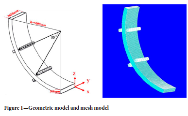
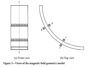
Figure 1 depicts the slab's dimensions and mesh model. The slab dimensions are 360 mm (thickness) x 2050 mm (width), and the inner arc diameter is 10 m, the iron core diameter is 240 mm, and the length is 2050 mm. The electromagnetic stirring mechanisms are situated at 30° and 60° with respect to the slab.
Magnetic field model parameters
The construction of the electromagnetic stirrer is critical. It has a direct impact on the working efficiency of electromagnetic stirring and is even related to the question of whether molten steel can be stirred at all. As a result, an explanation of the structure of the electromagnetic stirrer is essential.
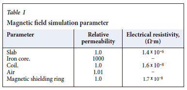
The essential simulation parameters of the magnetic field can be determined using mathematical modelling-- and the structural properties of the electromagnetic stirrer, as indicated in Table I.
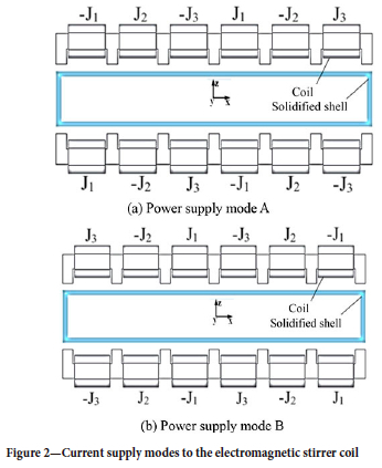
A three-phase travelling wave magnetic field is used in this paper. Figure 2 depicts the method of feeding current to the electromagnetic stirrer coil using two different power supply modes A and B.
Mathematical model
Assumptions
When researching magnetic field laws, it is critical to develop acceptable assumptions. The following assumptions can be made for the purpose of modelling the magnetic field in ANSYS.
> Molten steel is a conducting liquid that is incompressible.
> All the physical properties of molten steel are scalar constants.
> The slow flow of molten steel has little effect on the electromagnetic field. The wavelength of low-frequency electromagnetic waves at 10 Hz is extremely long (about 30 000 km, or roughly the diameter of the Earth). Therefore, in everyday practical applications (such as interior environments, within electrical equipment, etc.), such electromagnetic waves can be considered quasi-static -fields (Yang et al., 2019).
Magnetic field governing equations
Based on the above assumptions, the governing equations of the slab magnetic field are (Yang et al., 2019).
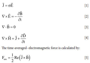
where H is the magnetic field intensity (A/m), E is the electric field intensity (V/m), B is the magnetic flux density (T); s is the electrical conductivity (S/m), D is the electric flux density (C/m), t is the time (s),and Re is the real part .
Boundary conditions and numerical solution
The slab area is placed within the air domain, which has a spherical shape and can effectively surround the magnetic field lines created by the coil in the air domain. The slab is grid-based on a uniform hexahedral mesh, the coil and iron core are grid-based on a nonuniform hexahedral mesh, and the air domain is grid-based on a nonuniform tetrahedral/hexahedral mesh. The calculating domain contains 390 000 elements in total according to the traditional calculation of the number of elements (Yang et al., 2022).
The magnetic induction intensity in the calculation domain is initially zero, the electromagnetic induction intensity is zero at infinity, the magnetic field is concentrated near the electromagnetic stirrer, and the phase angle difference between adjacent coils is 120°. Outside the air domain, the magnetic field line-parallel boundary condition is utilized since the magnetic field lines are closed.
The ANSYS Emag software package solves Maxwell's equations to perform a harmonic calculation of the 3D distribution of the electromagnetic field in the calculation domain.
Results and analysis
Figure 3 depicts views of the magnetic field geometric model to help clarify the problem. The A-A section represents the slab's centre symmetry plane in the y-axis direction; the B-B and C-C sections are sections of the electromagnetic stirrer's central axis at the 30° and 60° positions, respectively.
Magnetic field model validation
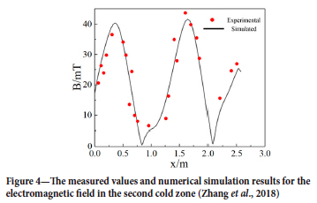
Figure 4 indicates that the simulated magnetic induction values correlate well with the measured values. The magnetic induction intensity on the centreline shows two peaks, the highest at 1.65 m and 41.6 mT, and the other at 0.36 m and 40.4 mT. The difference between the measured and simulated values at 0.62 m is 8.1 mT, whereas the difference between the other observed and simulated values is less than 3.5 mT. Because the calculation error is within the acceptable range, the numerical simulation results are trustworthy. The errors in numerical calculations and experimental values are primarily due to the experimental environment, numerical assumptions and model restrictions, experimental operating abilities, and calculation methods.
Magnetic flux density distribution
The difference in energization method directly determines the difference in magnetic field distribution. The magnetic field distributions of the B-B section and the C-C section are the same if the electrification mode of two pairs of stirring rollers is mode A or mode B (Figure 2); if the two pairs of stirring rollers are electrified in opposing ways , the distributions of the B-B and C-C section are opposite, as seen in Figures 5 and 6.
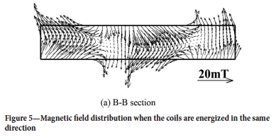
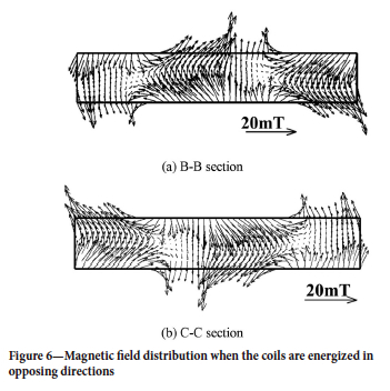
Figures 5 and 6 demonstrate that the maximum magnetic induction strength in the two sections is 20 mT, and the profile for each section is trimodal, with the peak at the horizontal centre being higher than the peaks at the left and right ends. As a result, the magnetic field on the strand's surface is stronger than that in the centre because the strand's surface is closer to the electromagnetic stirrer.
Figure 7 depicts the electromagnetic force distribution in the B-B section and C-C sections when the linear coil of the stirring roll is electrified at the 30° and 60° positions of the slab. The two sets of electromagnetic stirrers are in mode 1. The electromagnetic force is axisymmetrically distributed, with each section's electromagnetic force obliquely pointing to the central axis, and aligned along the same direction from left to right, with a value of roughly 1000 N/m3.
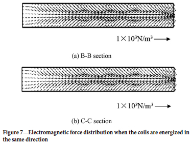
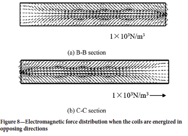
Figure 8 shows slab distribution of electromagnetic force at the electromagnetic stirring device, where the electromagnetic stirring device is located at 30° and 60° of the slab. The electromagnetic forces of the B-B section and the C-C section are both axisymmetrically distributed, and the directions of the electromagnetic forces of the respective sections point obliquely. The central axis and orientation of the two portions are opposed, and the value is approximately 1000 N/m3. In general, when the amplitude of the current is the same but the method of energizing the coils differs, the magnitude of the electromagnetic force is the same but the direction is reversed.
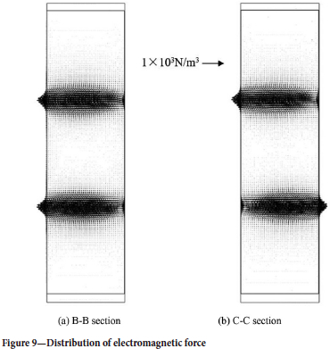
The electromagnetic force distribution of the two pairs of stirring rollers when not in operation is depicted in Figure 9. The electromagnetic force directions are the same when the same energization method is employed; when opposiing energization methods are utilized, the electromagnetic force directions of the two pairs of stirring rollers are opposed. The electromagnetic force has a maximum value of 1000 N/m3, which will not affect the stability of the cast.
The influence of frequency and current on the magnetic field
Figure 10 depicts the magnetic flux density distribution along the centreline of the B-B section. The magnetic flix density has a trimodal distribution across the breadth of the slab, with the middle peak the highest. The magnetic flux density gradually increases with increasing current, but the magnetic field distribution remains constant. The left peak appears at 0.1 m, the centre peak at 1.0 m, and the right peak at 1.8 m.
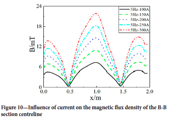
Figure 11 depicts the effect of current on the magnetic flux density at the centre point of the B-B section. An increase in the current from 150 A to 250 A causes the magnetic flux density to increases from 10.9 mT to 18.4 mT. In other words, for every 1 A increase in current, the magnetic flux density rises by 0.075 mT.
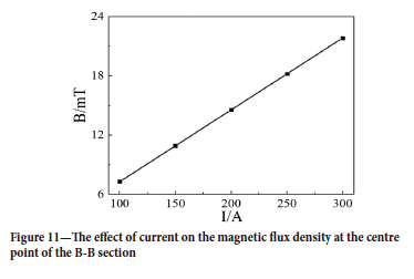
The relationship is described by Equation [6]:

Figure 12 depicts the effect of current frequency - on the flux density distribution along the B-B section centreline. In contrast to the effect of current, the distribution curve varies with frequency. With increasing frequency, the two minima in the distribution shift to the left, with the minimum value on the right undergoing a larger shift.
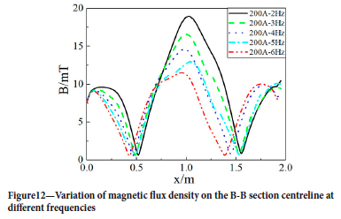
Figure 13 depicts the effect of frequency on magnetic induction at the central point of the B-B section. The flux density drops from 18.5 mT to 11.5 mT as the current frequency increases from 2 Hz to 6 Hz. That is, the flux reduces by 1.75 mT for every 1 Hz rise in frequency.
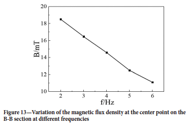
The relationship is given by:

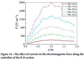
Figure 14 depicts the distribution of electromagnetic force along the B-B section centreline. The electromagnetic force steadily increases as the energizing current is increased, but the distribution law of the electromagnetic force remains the same; the closer to the centre, the greater the change in magnitude of the electromagnetic force.
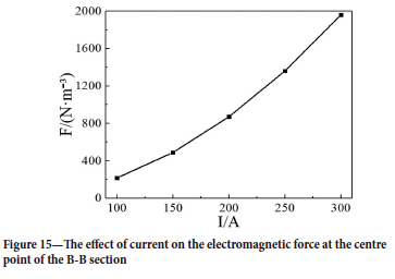
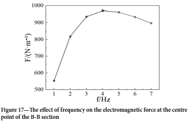
The effect of current on electromagnetic force at the central point of the B-B section is depicted in Figure 15. As the current is increased from 150 A to 250 A, the electromagnetic force at the centre point increases from 480 N/m3 to 1380 N/m3. The electromagnetic force is proportional to the square of the current:
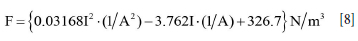
Figures 16 and 17 depict the variation of the electromagnetic force at the centre line and centre point of the B-B section with increasing frequency=. Figure 17 shows that the electromagnetic force at the cross-section's centre increases first and then diminishes. This is because the electromagnetic force is determined by both the induced current and the flux density. The current increases as the frequency increases, but the flux density drops. The figure shows that the electromagnetic force reaches its maximum at a current frequency of 4 Hz.
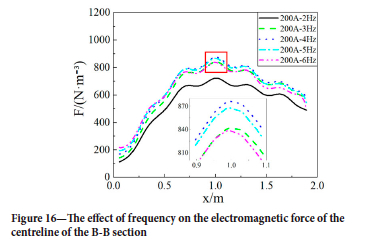
At the central point of the B-B section, the curve of electromagnetic force and frequency consists of two parts.
The second segment follows a linear expression (5 Hz to 7 Hz):

Conclusions
ANSYS simulations were used to model the magnetic field characteristics under electromagnetic stirring in the secondary cooling zone of a continuous caster, and the effects of changes in current and frequency in the magnetic flux intensity and electromagnetic force distribution studied. The main conclusions are as follows.
> The magnetic flux intensity in the B-B and C-C sections (sections of the stirrer's central axis at positions of 30° and 60°, respectively) exhibits a trimodal distribution, with a large (20 mT) central peak and a smaller peak on each side. The electromagnetic forces in the B-B and C-C sections are axisymmetrically distributed, with a maximum value of 1000 N/m3.
> The direction of the electromagnetic force is the same at the 30° and 60° positions of the arc-shaped slab when the power supply method is the same. When opposed energization methods are utilized, the electromagnetic forces generated have opposite polarities.
> As the energizing current increases, so does the magnetic induction. The magnetic induction at the centre point of the B-B section increases with increasing current frequency.
> The electromagnetic force increases with increasing current. Withincreasing frequency, the electromagnetic force at the centre point of the B-B section first increases, reaching a maximum at 4 Hz, and then declines.
> The relationships between magnetic flux density, current, and frequency at the centre of the B-B section are
B = {0.075I-(1/A)-0.3}mT
B = {-1.75f-(1/Hz)+22}mT.
> The electromagnetic force and current at the central point of the B-B section are related by:
F = {0.03168I2-(1/A2)03.762I-(1/A)+326.7}N/m3.
With increasing frequency the electromagnetic force at this point at first increases following a parabolic relationship:
F = {-21((f-4.3)-(1/Hz)2)+970}N/m3
and then decreases in a linear fashion at frequencies above 5 Hz:a
F = {-1.65f-(1/Hz)+51.5}N/m3
Conflict of interest
The authors declare that there is no conflict of interest.
Acknowledgement
We thank the University of Science Technology of Liaoning United Fund (HGSKL-USTLN(2022)07), National Natural Science Foundation of China(Grant NO.NSFC52074151) the Education Department Project of Liaoning Province(Grant NO.2020LNJC03), and the Department of Science & Technology of Liaoning Province(Grant NO.2022JH2/101300079) for financial support of the current work.
References
An, H.H., Bao, Y.P., Wang, M., and Yang, Q. 2019. Electromagnetic torque detecting for optimization of in-mould electromagnetic stirring in the billet and bloom continuous casting. Ironmaking & Steelmaking, vol. 46. pp. 845-854. [ Links ]
Beitelman, L. 1990. Effect of mold EMS design on billet casting productivity and product quality. Canadian Metallurgical Quarterly, vol. 38, no. 5. pp. 301-309. [ Links ]
Javurek, M., Barna, M., Gittler, P., Rûckenschaub, K., and Lechner, M. 2008. Flow modelling in continuous casting of round bloom strands with electromagnetic stirring. Steel Research International, vol. 79. https://doi.org/10.1002/srin.200806174 [ Links ]
Jiang, D.B. and Zhu, M.Y. 2015. Flow and solidification in billet continuous casting machine with dual electromagnetic stirrings of mold and the final solidification. Steel Research International, vol. 86. https://doi.org/10.1002/srin.201400281 [ Links ]
Lei., H., Jiang, J.M., Yang, B., Zhao, Y., Zhang, H.W., Wang, W.X., and Dong, G.W. 2018. Mathematical model for collision-coalescence among inclusions in the bloom continuous caster with M-EMS. Metallurgical and Materials Transactions B, vol. 49. doi: 10.1007/s11663-018-1186-y [ Links ]
Limoges, J. and Beitelman, L. 1997. Continuous casting of carbon and alloy billets with in-mold dual-coil electromagnetic stirring system. Iron and Steelmaking, vol. 24, no. 11. pp. 49-57. [ Links ]
Liu, C.T. 2010. Refined model development and performance assessment of a linear induction-type electromagnetic stirrer. IEEE Transactions on Magnetics, vol. 46. p. 3724. [ Links ]
Sivesson, P., Hallen, G., and Widell, B. 1998. Improvement of inner quality of continuously cast billets using electromagnetic stirring and thermal soft reduction. Ironmaking & Steelmaking, vol. 25. pp. 239-246. [ Links ]
Trindade, L.B., Nadalon, J.E.A., Contini, A.C., and Barroso, R,C. 2017. Modeling of solidification in continuous casting round billet with mold electromagnetic stirring (M-EMS). Steel Research International, vol. 88. https://doi.org/10.1002/srin.2016003191600319 [ Links ]
Trindade, L.B., Vilela, A.C.F., Filho, A.F.F., Vilhena, M.T.M.B., and Soares, R.B. 2011. Numerical model of electromagnetic stirring for continuous casting billets. IEEE Transactions on Magnetics, vol. 38. p. 3658. [ Links ]
Wang, T., Wang, E.G., Delannoy, Y., Fautrelle, Y., and Budenkova, O. 2022. Effect of vertical electromagnetic stirring on solute distribution in billet continuous casting process. Journal of Iron and Steel Research International, vol. 29. pp. 132-143. [ Links ]
Yang, B., Lei, H., Bi, Q., Jiang, J.M., Zhang, H.W., Zhao, Y., and Zhou, J.A. 2019. Electromagnetic conditions in a tundish with channel type induction heating. Steel Research Internationsl, vol. 89. https://doi.org/10.1002/srin.201800145 [ Links ]
Yang, B., Liao, X.W., Liu, K., Zhao, C.L. and Han, P. 2022. Numerical simulation of residence time distribution (RTD) in tundish with channel type induction heating. JOM, vol. 74, no. 5. pp. 2129-2138. [ Links ]
Zhang, K., Chen, S.F., Yang, B., Liu, T.y., Zhao, Y., and Lei. H. 2018. Study on arrangement of S-EMS rollers in secondary cooling zone of slab continuous casting machine. Journal of University of Science and Technology Liaoning, vol. 41. pp. 335-340+350. [ Links ]
 Correspondence:
Y. Ren
B. Yang
Email: yang583766560@163.com
Received: 16 Jan. 2024
Accepted: 25 Feb. 2024
Published: March 2024

