


Services on Demand
Article
 English (pdf)
 Article in xml format
 Article references
Indicators

Related links
-
 Cited by Google
 -
 Similars in Google
Share

 Permalink
Journal of the Southern African Institute of Mining and Metallurgy
On-line version ISSN 2411-9717
Print version ISSN 2225-6253
J. S. Afr. Inst. Min. Metall. vol.123 n.12 Johannesburg Dec. 2023
http://dx.doi.org/10.17159/2411-9717/2583/2023
PROFESSIONAL TECHNICAL AND SCIENTIFIC PAPERS
Flyrock in surface mining Part II - Causes, sources, and mechanisms of rock projection
T. SzendreiI; S. ToseII
IDynamic Physics Consultants, Johannesburg, South Africa. ORCID: http://orcid.org/0000-0002-5693-7850
IIAECI Mining Explosives, Johannesburg, South Africa. ORCID: http://orcid.org/0000-0002-2514-5308
SYNOPSIS
The fracturing and movement of rock that occurs in the vicinity of a stemmed borehole charge in open pit mining operations are described by examining the effects of the emitted stress waves - shock and elastic - and the expansion of high-pressure detonation product gases. Three principal modes of momentum transfer to fractured rock are identified, all linked to gas expansion work. This work can be delivered radially (burden), axially (stemming), and in the collar zone (cratering). Flyrock is generated under unusual combinations of blast parameters and rock properties. Although infrequent and seldom predictable, the generation of flyrock can nonetheless be interpreted and modelled in terms of the principal mechanisms of rock projection described in this study. The physical processes underlying these principal mechanisms are identified and will permit the development of predictive models for flyrock velocities.
Keywords: flyrock momentum, stress waves, gas action, cratering, face-burst, stemming.
Background
Flyrock can be defined as the throw of rock fragments from a surface or open pit blast that travel distances beyond the expected range or a pre-set safety zone, and which pose a serious threat of damage to property and infrastructure, and injury to people in and around the mine property. In a previous paper (Szendrei and Tose, 2022) it was pointed out that empirical approaches to the prediction of flyrock throw distances are necessarily limited for the reason that such models are unable to predict the two primary determinants of throw distance - flyrock mass and initial velocity.
Conventional models of flyrock do not consider the physical mechanisms of rock projection nor their motion through air, and are based on statistical correlations that are derived from measured throw distances at specific sites. It was further pointed out that two well-known models of flyrock velocity (Lundborg et al, 1975; McKenzie, 2009 that are based on more comprehensive ballistic trajectory calculations, are flawed. The Lundborg model for maximum throw distance is based on a model of momentum transfer to rocks that is not supported by present-day knowledge of the properties of blast waves and overestimates the throw distance by factors of 2 or more. McKenzie (2009) calibrated his scaled-depth-of-burial model against Lundborg's velocity values and therefore his predictions of flyrock velocities and throw distances are also questionable.
It is evident that progress in the analysis and prediction of flyrock would require a deeper understanding of the mechanisms by which rocks acquire momentum in a blast and are propelled from the bench. We further pointed out that on a fundamental level, and irrespective of any details of blast design or rock mass properties, the range of a flyrock of a given mass and shape depends only on the launch velocity, and its prediction would require calculation by a realistic trajectory model that includes air drag.
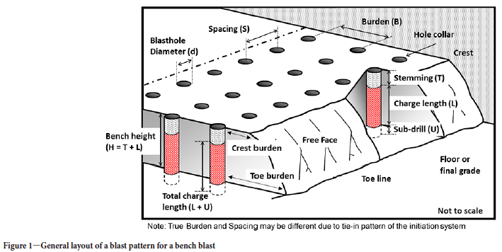
Figure 1 is a schematic illustration of the general layout of a bench blasting operation and the terminology used to describe the elements of the blast pattern, many of which are relevant to discussions of flyrock.
The 'burden' that is of direct relevance to flyrocks is the separation of the first row of blast-holes from the free face, which is generally vertical. As noted later in this study, the as-drilled burden may vary significantly about its nominal planned value.
The aim of this study is to identify the physical processes by which fragmented rocks acquire velocities that propel them to distances of some hundreds of metres from the muckpile in the short period of time (tens of milliseconds) between the detonation of a column charge and the throw of rock fragments from the bench.
Causes and sources of flyrock
Many workers have attempted to identify the reasons for the occurrence of flyrock, and based on some of these perceived causes various equations have been proposed to predict flyrock throw distances. These equations are normally based on various parameters of the blast design and charge load, and less often on the properties of the rock mass. Raina, Murthy, and Soni (2015), for example, listed 13 parameters from published studies on the causes of flyrock, and 16 parameters used in various models of flyrock range. It has been noted (e.g. Raina and Murthy, 2016) that there is often a disparity between the perceived causes of flyrock and the measurable empirical parameters that are used for the prediction of range. This may be due to the difficulty of defining appropriate parameter values that would link, for instance, the influence of rock geotechnical quality or delay timing errors to flyrock throw distances.
Ghasemi, Sari, and Altaei (2012) used seven parameters to develop a prediction equation for throw distance by multiple regression analysis of linear and nonlinear combinations of blast parameters. In contrast, Raina and Murthy (2016) conducted an artificial neural network (ANN) study that included 21 parameters of blast design, explosive, and rock properties. Despite their complexity, studies of this nature have not yet yielded a globally applicable model that is capable of ab initio predictions of flyrock throw distances.
The cited causes of flyrock may be grouped in five categories:
► Basic geometrical details of the blast pattern and stemming design
► Charge and loading details
► Errors in blast plan implementation, especially those associated with drilling and charge loading
► Delay timing and forward relief
► Rock mechanical properties and geotechnical quality.
The most influential parameters for flyrock generation are generally recognized as being:
► Insufficient confinement of the charge in general, and the burden in particular
► Insufficient or inadequate stemming
► Specific charge (kg/m3) and loading deviations
► Delay timing
► Rock defects and geological anomalies.
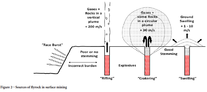
Three general sources of flyrock projection from the bench have been recognized, as illustrated in Figure 2.
The velocity values and the indicative angular spread of rock expulsion are based on field measurements and data collected by AECI Mining Explosives over many of its operations across Africa. Swelling of the ground surface is included in Figure 2 as it is relevant to the interpretation of the so-called scaled-depth-of-burial model of flyrock. A schematic illustration of an incorrect burden resulting in a face-burst is shown in Figure 3.
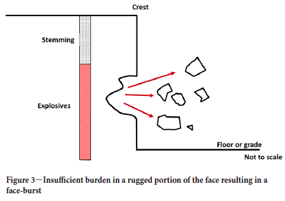
A face-burst occurs when a jet of high-pressure gas follows a path of least resistance through the burden and projects rocks at velocities that may be multiples of expected burden throw velocity.
Gun-barrelling (rifling) occurs when the stemming is inefficient (too short or absent or of an inadequate material), and is ejected from the borehole at high velocity and gas pressure. This can also occur when unusually high pressure develops in the borehole. Gun-barrelling is usually accompanied by extensive damage to the hole collar.
Cratering occurs on top of the bench as a consequence of the action of the charge load that is present in the collar zone, the type and length of the stemming material, and is considered to be the major source of excessive flyrock as well as wild flyrock. This effect may be pronounced when the collar rock is weak and/or damaged due to poor drilling practises, in particular the collaring of the hole and over-drilling of the previous block (excessive sub-drill), resulting in overbreak in the floor and/or prefractured due to the blast design. Control of the loading of broken rock material from the previous blast and over-digging can also contribute. Insufficient stemming length, and the use of drill cuttings instead of a suitable crushed angular stone may exacerbate the situation.
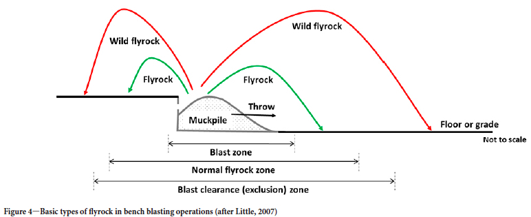
The above sources of flyrock generate three distinct types of thrown rock (Figure 4):
Throw is the planned forward casting of blasted, fragmented rock from the burden to form the muckpile within the blast zone.
Flyrock is the undesired projection of broken rock beyond the blast zone. While undesirable, flyrock is not a safety hazard if it falls within the blast exclusion (or clearance) zone.
Wild flyrock is the unexpected projection of flyrock beyond the exclusion zone, often when there is an abnormality in the blast or rock mass. It is a serious safety hazard for workers and the general public.
The question of the mechanisms by which flyrock is projected from the above sources and at what velocities requires the examination in some detail of the processes that result in the fracturing and throw of rock.
Rock fracture and movement - a historical perspective
Stress wave action
Historically, a number of theories concerning rock fragmentation and cratering by blasting have been proposed. The most well-known (often mistakenly termed the 'shock wave' theory) relied heavily upon tensile scabbing and spalling as the fracture mechanism (Card, 1962). In brief, the explosion pressure in the borehole drives a short-duration, high-amplitude stress wave into the surrounding rock mass as a shock wave. This creates a crush zone and a dense radial pattern of cracks around the blast-hole before propagating outward as an elastic wave at the speed of sound in the rock. Because of the relatively high compressive strength of rocks, the advancing stress wave produces no further damage until it is reflected at a free face as a tensile wave. Fracturing will then occur where the intensity of the inward moving tensile wave exceeds the fracture strength of the rock, this being much less than its compressive strength (1/10 to 1/40). If the original stress pulse is strong enough, several such fractures will form in planes normal to the returning tensile wavefront. The 'shock wave' theory states that the cracked rock is displaced outward by spalling and slabbing. Later modifications of the theory admitted a greater role for radial fractures (e.g. Hustrilid, 1999) but left the essential element of the theory unchanged - tensile fracturing is the primary cause of cratering (and hence of rock throw).
While it cannot be denied that tensile stress projection of fragments from the free face can create shallow craters, it is observed that a crater which extends back to the borehole will involve a much greater volume of rock than can be attributed to spalling. Post-mortem observational evidence has shown that the final fracture surface for the crater is created by fractures that start at the blast-hole and extend to the free surface. This directly contradicts the tensile/spalling model, in which fractures propagate from the free surface inward.
Sellers et al. (2013) noted two other major and demonstrable shortcomings of the tensile fracture model. Its predictions of burden break-out angle as a function of the burden cannot be reconciled with field observations. The model is also unable to account for the energy deficit noted by Ouchterlony et al. (2004). Up to 50% of the chemical energy released in the explosion of a borehole charge cannot be accounted for in terms of processes that underlie the elastic theory of rock breaking.
It is now generally accepted that the tensile stress fracturing model should be replaced by a broader model that includes the influence of longer duration pressure of gaseous products of detonation. Over the years there has been much debate over the relative contributions of these two very different types of loading to the fracturing, fragmentation, and displacement of rock.
Gas pressure action
Based on laboratory-scale experiments, Kutter and Fairhurst (1971) demonstrated that the role of reflected stress waves in single hole cratering is not only to cause scabbing, but also to extend the radial fractures in the vicinity of the borehole towards the free face. They also pointed out that the relatively small amount of energy carried away from the borehole by stress waves (5-10%) indicates that the major part of the energy of explosion must be associated with the internal energy of gases remaining in the borehole after the explosion. They argued that this high-pressure gas penetrates into the radially cracked zone surrounding the borehole and creates a pressurized 'equivalent cavity' equal in size to the volume defined by the tips of the radial cracks. The stress-induced static stress field set up in the rock around the equivalent cavity would be sufficient for extensive crack propagation and thereby complete the fragmentation of the rock mass. The Kutter and Fairhurst (1971) model of fragmentation does not predict the velocity of the thrown rock.
Fourney et al. (1993), on the other hand, based the mechanisms of cratering on the expansion of gases from the borehole. The displacement of rock is made possible by its prior 'preconditioning' through the formation of a network of radial and hoop fractures in the dynamic stress wave phase of a blast. Following this phase, high-ressure gas the acts on the greatly weakened rock mass around a borehole and begins to move the inertial mass in the direction of least resistance - towards the free face. This movement opens and extends the radial cracks to the free face and the fractured material is thrown from the crater.
Other than clearly being associated with gas expansion work, the mechanism by which the thrown material acquires velocity is vague. Sellers et al. (2013) noted that if significant flow of gas into fractured rock mass does occur, it would decrease the energy of explosion product gases and, contrary to conventional thinking, would not enhance heave. Nonetheless, it is evident that gas pressure plays an important role in displacing fractured rock. The details of this action and the sequence of events following the to-and-fro passage of stress waves through the rock mass remain vague.
Rock fracture and movement - A new perspective
Stress wave action
The early theories of tensile cracking and cratering were somewhat limited in that they did not consider some specific characteristics of shock wave action and stress wave propagation that ultimately determine the nature and extent of fracturing of the rock mass. A description is given below of these aspects of stress wave action in sufficient detail to identify the physical principles underlying the mechanics of rock projection.
Borehole expansion
In recent years it has been recognized that immediately following the detonation of the charge, the borehole undergoes rapid radial expansion under the influence of a shock wave that is transmitted by the detonation product gases into the rock through the skin of the borehole. This typically results in a 2- to 5-fold volumetric expansion(in fully coupled holes (Cunningham and Szendrei, 2004; Cunningham, Sellers, and Szendrei, 2007). This expansion is central to the properties of the stress wave that subsequently propagates away from the borehole.
The crush zone and the ring of dense radial cracks around the expanded borehole mark the radial extent of inelastic rock response to the passage of the shock wave as it propagates away from the blast-hole. The periphery of this zone of inelastic rock response marks the point where the intensity of the shock wave has decreased from its initial value of some gigapascals (GPa) to a value equal to the strength of the rock, commonly taken to be its unconfined compressive strength (UCS). Thereafter a compressive elastic stress wave (σc) propagates outward with this initial amplitude at the speed of sound in the rock, typically 3000-6000 m/s. The duration and length of the stress pulse are directly related to the time of expansion of the borehole to its final size.
Radial fractures
After propagating away from the expanded borehole, the compressive stress pulse soon develops a tensile component in its trailing portion as a consequence of the divergent movement of rock particles behind the wave front in cylindrical symmetry. Tensile forces (σt) acting normal to the direction of propagation induce radial splitting of the rock. The strength of these tensile forces at first increases with radial distance, then decreases as the wave amplitude attenuates with increasing distance from the borehole. The net effect is that radial fractures extend only part of the way to the free face. Once the stress pulse has passed by, the rock is stress free and radial fracture growth ceases.
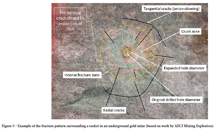
Figure 5 illustrates the effects of close-range stress wave action on rock surrounding a blast-hole.
In addition to the delineation of various rock response zones, three particular features are notable in Figure 5, namely (i) an enlarge borehole is clearly seen (56% radial and 2.4 volumetric expansion); (ii) the crush zone is of limited extent - 2½ hole diameters in this instance; (iii) tangential (tensile) cracks are seen only outside the intense fracture zone.
Of course, radial fractures are not limited to the rock mass between the boreholes and the bench face. Radial fractures would be generated in the full 360o circle around each borehole. The growth of these fractures would cease as the compressive pulse propagates away in the bench behind the face as an ever-decreasing ground vibration. When multiple boreholes are detonated the rock between two adjacent holes would largely be traversed by radial fractures extending from each hole.
Attenuation of elastic waves
At distances from the borehole that are of interest in bench blasting (some metres) viscous damping of elastic stress waves may be neglected and peak intensity of the elastic pulse will decay, mainly with geometrical attenuation. In the cylindrical symmetry that exists between the column charge and the bench face, wave amplitude will decay as the inverse of the square root of the radial distance. Vertically, between the base of the stemming and the bench top, wave propagation has a three-dimensional character and amplitude will decrease with the inverse of the propagation distance. These attenuation laws permit the calculation of the relative amplitudes of stress waves arriving at various locations on the bench from the borehole.
Reflection at free faces
Reflection of a compressive pulse at a free face results in an inward-moving tensile pulse of the same amplitude and duration, but only in the event that the angle of incidence (θ) on the free face is zero (i.e. along the surface normal). At larger angles of obliquity both tensile and shear stresses are generated on reflection. Importantly, the amplitude of the reflected tensile wave diminishes with obliquity and generally becomes vanishingly small quite rapidly when 0 is 40-60°. This critical angle is specific to the rock and is a function of its Poisson's ratio, which is a measure of its rigidity.
As the reflected tensile wave runs back towards the borehole, fractures parallel to the wavefront are generated at distances from the free face where the net tension, σt + σc, exceeds the fracture strength of the rock. If the incident pulse is strong enough, several such fractures can form parallel to the wave front in a process called slabbing. This process does not necessarily result in outward projection of scabbed material. This would require a sufficient level of trapped momentum between the two faces of the scabbed material, a condition that is seldom met except in the case of small fragments spalled from the surface.
Because of the obliquity effect in reflection, the rock mass is mostly fractured in tension only within certain limiting angles. The well-fractured mass is wedge-shaped in the burden (cylindrical symmetry) and cone-shaped in the collar zone (spherical symmetry). In both cases, the apex is at the borehole, the opening angle is about 100o, and the base is located at the free face.
Tangential (hoop) fractures
The state of stress in the reflected tensile wave is biaxial - both radial and lateral stress components are tensile so that fractures may form both parallel and normal to the wave front. The effects of biaxial tensile forces are particularly notable when the returning wave runs over the radial cracks in the vicinity of the borehole and connects them together with circumferential (hoop) fractures. Additionally, the radial cracks, particularly those that are within the wedge of strong tensile action, may undergo extension towards the free face when exposed to renewed tensile forces. Crack extension is a less energy-demanding process than the formation of new cracks.
Fracturing is not limited to an outgoing and an incoming stress wave only. In regions of the rock mass where more than one free face exists, fracturing becomes more complex. The amplitudes of multiple elastic waves - compressive and tensile - can be summed vectorially at any location. This superposition of waves that may be travelling in different directions and with different amplitudes can yield a resultant amplitude that is strong enough to cause localized fracturing. This effect will be especially important in regions of the rock mass that may be traversed by various reflected and re-reflected waves, such as the collar zone.
Collar zone fracturing
The collar zone may be defined as the rock mass between the top of the charge column and the bench top. Rock in this zone would not experience the same levels of stress wave fracturing as detailed above, for a number of reasons. The specific charge (kg/m3) in the collar zone is less than in the rest of the blasted volume. Also, travel distances for the compressive pulse to free faces on the top and sides of the bench can be longer than radially through the burden in front of the charge columns, and the angles of incidence on the free face would generally be higher. These factors would reduce the strength of the compressive pulse arriving at free faces and weaken the subsequent action of the reflected tensile wave. Some contribution to fracturing from the superposition of stress waves can be expected, but this effect would be localized and confined to specific directions and planes that are defined by the geometrical disposition of free faces and the loci of intersection of stress waves.
All in all, it is unlikely that the collar zone would be as well fractures as the rest of the burden rock. This expectation is borne out by Chiapetta's observation (2009) that the bulk of oversize derives from the collar zone and may constitute up to 40% of the muckpile.
Movement of fractured rock
Although the burden from grade to bench top is fractured with a network of radial and tangential cracks, it remains in place at the completion of stress wave action. Except for some possible spalling from free faces and the throw of loose rocks from the top of the bench as momentum missiles, there would be no large-scale displacement and dispersion of broken material. It is the central tenet of our analysis of the causes of flyrock that the movement of rock and its projection at various velocities is the consequence of gas action. Gas action is not mediated by rapid infiltration and pressurization of fractured rock or by extension of existing cracks, but by the mass movement of rock in the burden and collar zone.
At the completion of borehole expansion, detonation product gases are still retained in the expanded holes. Momentum is transferred to fractured rock only when the internal energy of the confined gas is converted by expansion work to kinetic energy of the rock mass. The way this energy is delivered is determined by the various paths of expansion followed in the burden, stemming, and collar zone. These paths of expansion are described in the following section. In addition, two other possible modes of momentum transfer to rocks (as historically postulated) are briefly considered -stress wave action and air blast.
Mechanisms of rock projection
The accumulation of explosion product gases in the (initially) closed volume of an expanded borehole possesses considerable internal energy due to its high pressure. Although generated under detonation shock conditions, the released gas quickly equilibrates in the borehole behind the detonation shock front. This pressure acting on the enclosing rock surfaces - borehole walls and the base of the stemming column - accelerates the rock in proportion to the pressure (force per unit area). This fundamental motive force manifests itself in various ways by which momentum is transferred to rock. The following modes of transfer can be identified as direct consequences of the action of gas pressure:
(i) Burden movement and face-burst
(ii) Stemming ejection and collar damage
(iii) Bench top cratering.
Stress wave action and blast wave impulse have been cited in the literature as causes of flyrock, and are briefly considered as possible modes of momentum transfer.
Burden movement
Observational evidence (e.g. high-speed videos) indicates that the forward displacement of burden rock may be conceptualized as the opening of a gap between a row of boreholes and the bench face, at least on the scale of metres. For modelling the throw of burden in general and the throw of flyrock from relatively small, localized areas of the face in particular, a physically insightful definition of the burden is the inertial mass per unit area (Me). This area is taken normal to the radial direction and is large enough to include deviations and imperfections in the face and in the geology of the burden rock.
In related explosives technology areas of military science and engineering, it is common practice to apply the Gurney approach to the prediction of projection velocities of inert materials in contact with explosive charges (Walter and Zukas, 1989). The key concept of the Gurney technique is that the energy liberated by detonation resides as the internal energy of an equi-volume quantity of highly compressed detonation product gases and only a certain fraction of this energy, Eg (MJ/kg), can be converted to mechanical work by gas expansion. This fraction is about 70% for high explosives such as TNT, RDX, and HMX (Cooper and Kurowski, 1996), and somewhat less, 55-65%, for various formulations of ANFO and emulsions (Essen et al., 2005). The Gurney energy is an intrinsic property of explosives and is considered to be an accurate estimate of the work capacity of an explosive as applied to its surroundings.
The Gurney velocities of projection (VB) have been calculated for many geometrical arrangements of explosives and inert materials. The particular combination that may be of direct relevance to bench blasting is the so-called asymmetric sandwich arrangement, where the explosive (C) is sandwiched between two 'plates. One plate of mass MB is free to move forward and may be associated with the burden. The second plate is a heavy 'tamper' of mass N which prevents any significant backward movement and may be associated with the essentially rigid rock mass of the bench behind the row of blast-holes.
Gurney velocity predictions (VB) are generally of the following functional form:
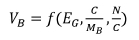
where the shape of the function f is case-specific and can be defined in planar, cylindrical, or spherical symmetry. It is intuitively obvious that high values of the ratio G:MB would yield high values of burden velocity.
Many geometrical details contained in the blast plan will contribute to the variation of MB, e.g. B, S, H, height of stemming, and hole diameter as defined in Figure 1, together with drilling deviations and rugged face profile as well as geological anomalies (cavities, fissures, weak strata, mud etc.). It is more insightful to consider the inertial mass per unit area (MB) as pBLB where pB is the effective density of the inertial mass along an expansion path of length LB through the burden to the face.
Clearly, both pB and Le may show considerable variation over the face. The upper limit is set by competent rock of (say) density 2500 kg/m3 and a burden of 4 m, yielding pBLB = 10 000 kg/m2. A lower limit would be an open fissure with pBLB approximately zero. Similarly, the effective charge mass per unit area of face may vary from the value defined by the nominal charge per linear metre to multiples of this value when the borehole intersects a cavity and other possible reservoirs of excess explosive. It is evident that both the specific charge (kg/m3) and linear charge density (kg/m) as defined in the blast plan are coarse estimates of the actual charge-to-mass ratio in the field ratio, which is the major determinant of burden movement.
The effective burden mass defined as pBLB may vary between wide limits from place to place on the face as would be shown, for instance, by diamond core drilling. Given this wide range of possible values and its influence on rock velocity, the Gurney model suggests that flyrock is generated when gas action drives fractured rock to unusually high velocities along pathways through the burden where the inertial resistance (pBLB) is exceptionally low. We suggest this is the root cause of face bursts.
Stemming ejection (gun-barrelling)
A second - and probably principal source of excessive and wild flyrock - is the stemming and hole collar, where two basic modes of rock projection may be operative. The first is 'gun-barrelling, whereby the stemming column is propelled upward by gas pressure acting on its base in a manner closely resembling the acceleration of a projectile in a gun barrel. The second mode is energetic rock projection by cratering in the collar zone.
As in a gun barrel, the expansion of gas behind the stemming converts its internal energy to work done in overcoming the inertial and frictional resistance of the stemming column. The response of the stemming to gas action would depend on its column length, type of material, bulk density, size and angularity of particulates, and frictional resistance at the blast-hole wall. Ejection of the stemming is usually accompanied by the throw of rock from the collar zone. The severity of collar damage would depend upon the 'muzzle blast' - the pressure and velocity of the plume of gas emerging from the collar. Normally the expanded blast-hole volume will determine the driving pressure at the start of stemming motion, usually the equivolume pressure in a fully coupled hole as described by Cunningham (2006). The 'muzzle' effect would be enhanced when the venting pressure is unusually high due to lack of forward relief, excessive charge load, and all factors that may influence delay timing and sequencing.
The influence of borehole pressure and many details of the stemming design on the violence of stemming ejection provides an explanation for why stemming has long been considered to be a critical element of blast design. Modelling stemming ejection along the lines of gun internal ballistics would enable calculations of the gas pressure and its streaming velocity at the 'gun muzzle, the bench top, as functions of various design details. Gas pressure and velocity at exit are seen as necessary initial conditions for the understanding of rock projection from the collar zone and as necessary inputs for the construction of models for the prediction of flyrock velocities from this zone.
Bench top cratering
This is easiest conceptualized in terms of the scaled-depth-of-burial (SDOB) model proposed by Chiapetta (1983) and Mackenzie (2009) and described in detail in the ISEE Blasters' Handbook (2018). In its original formulation the model predicted the depth of placement of a charge for maximum crater volume and made no predictions of the velocity of the ejected debris. The McKenzie (2009) version presented an equation to calculate the throw velocity. Szendrei and Tose (2022) pointed out that this equation is based on questionable assumptions and overestimates measured throw distances by factors of 2 to 10, as may be inferred from field observations presented by McKenzie (2018).
No model is known for the prediction of rock debris throw distances from crater blasting other than simple correlation equations based on cube root scaling of explosive mass (DDSB, 2009). Observational evidence indicates that rocks thrown from the bench top often possess the highest velocities. The cause of such high velocities remains unclear. Clearly, it must in some way relate to gas pressure generated by the buried charge and venting through the collar zone, together with the doming and eventual bursting of ground around the hole collar. Rocks ejected in such events would be dispersed at high angles, favouring maximum range of throw. This view requires further study in order to derive a quantitative physical mechanism for estimating the momentum of thrown rock.
Pressure pulses in air and rock
Szendrei and Tose (2022) demonstrated through calculations that air blast is a weak transmitter of momentum and unless implausibly large explosive charges are considered, it cannot propel sizeable rock fragments to far distances. Similarly, stress waves can fracture rock but the impulse transmitted by these waves is far too low to create dangerous flyrock.
Discussion
Shock phase
The importance of elastic stress wave action in fracturing rock has generally been acknowledged; the role of the shock wave emanating from the borehole immediately after the detonation of the charge has been less well recognized. While the details of detonation physics resulting in its formation have no direct influence on flyrock generation, the importance of the shock wave lies in two consequences that it leaves behind. One is the creation of an enlarged borehole containing detonation product gases; the other is its conversion to an elastic stress wave that propagates away into the rock mass. The former is the source of energy for the subsequent rock movement; the latter leads to pre-fracturing of the rock prior to gas action.
Gas action
The expanded borehole serves as a reservoir of pressurized gas, which will be of the order of 100 MPa for commercial blasting agents. The internal energy of this gas is the source of gas action on fractured rock that ultimately displaces and throws the rock from the bench. Many groups in the explosives and mining industries have presented numerical models of considerable complexity to track detonation and isentropic expansion of detonation product gases. An example of such work, based on AEL's i-Vixen code, was presented by Cunningham, Sellers, and Szendrei (2007) for pumped emulsion. Adiabatic expansion of high-pressure gas can be adequately modelled as a polytropic process.
Mechanisms of rock projection
Five possible mechanisms for the transfer of momentum to rock are considered in this study. Of these, two - blast wave impulse propagated through air and spalling and momentum fragments generated by stress waves in the rock - make no significant contribution to the throw of flyrock. The other three mechanisms derive from the action of detonation product gases and the work delivered along various paths of gas expansion. All recognized causes of flyrock can be interpreted as contributing in some way to gas expansion work, and hence to the transfer of momentum and kinetic energy to fractured rock. Although some flyrocks acquire exceptionally high velocities, their generation can nonetheless be interpreted within the parameters of the various modes of momentum transfer. Pre-fracturing of rock by stress wave action is seen as a necessary precursor to rock movement.
Flyrock velocity
Flyrock is seen as a by-product of the mass movement of rock by gas action due to unusual but plausible combinations of blast design, its implementation, and rock geotechnical details that enhance momentum transfer along certain pathways through the rock.
Conclusions
We have presented detailed arguments that the projection of flyrock from the sources, as illustrated in Figures 2 and 3, can be modelled in terms of concepts that are well established in related technological areas of military ballistics and engineering. These concepts are: Gurney energy and charge/inert mass geometry and interaction; internal ballistics of guns and the importance of projectile mass and wall friction; buried explosions and crater formation between the limits that yield the maximum volume or a camouflet. Through suitable adaptations of these concepts to the specifics of bench blasting and the introduction of appropriate initial conditions, it would be possible to establish the scientific underpinnings of flyrock projection and derive quantitative predictive models. This work is currently in progress.
References
Card Jr, D.C. 1962. Review of fracturing theories. Report no. UCRL-13040. Colorado School of Mines Research Foundation, Golden, CO. [ Links ]
Chiapetta, F. 2009. Combining electronic detonators with stem charges and air decks. Proceedings of the 9th Symposium on Rock Fragmentation by Blasting (FRAGBLAST9), Granada Spain. CRC Press, Boca Raton, FL. [ Links ]
Chiapetta, R.F., Bauer A., Dailey, O.J., and Burchell, S.J. 1983. The use of high speed motion picture photography in blast evaluation and design. Proceedings of the 9th Annual Conference on. Explosives and Blasting, Dallas, TX. International Society of Explosives Engineers, Cleveland, OH. [ Links ]
Cooper, P.W. and Kurowski, S.R. 1996. Introduction to the Technology of Explosives. Wiley-VCH, New York. [ Links ]
Cunningham, C.V.B. 2006. Blast hole pressure. What it really means and how we should use it. Fragblast, vol.10, no. 1. pp. 33-45. [ Links ]
Cunningham, C.V.B., Sellers, E., and Szendrei, T. 2007. Cavity expansion energy applied to rock blasting. Proceedings of the EFEE Conference of Explosives Engineers. European Federation of Explosives Engineers, Vienna. pp. 27-38. [ Links ]
Cunningham, C.V.B. and Szendrei, T. 2004. Cavity expansion by hypervelocity impact applied to blasthole expansion by detonation. Proceedings of the 30th Annual Conference on Explosives and Blasting Technique: Vol.1. International Society of Explosives Engineers, Cleveland, OH. [ Links ]
DDESB. 2009. Approved methods and algorithms for DOD risk-based explosive siting. Technical Paper 14, Rev. 4. Department of Defense Explosives Safety Board, Alexandria, VA. [ Links ]
Essen, S., Nyberg, U., Hiroyuki, A., and Ouchterlony, F. 2005. Determination of the energetic characteristics of commercial explosives using the cylinder expansion test. Swebrec Report no. 2005:1. Swedish Blasting Research Centre, Lulea University of Technology, Sweden. [ Links ]
Fourney, W.L., Dick, R.D., Wang, X.J., and Wei, Y. 1993. Fragmentation mechanism in crater blasting. International Journal of Rock Mechanics and Mining Science & Geomechanics Abstracts, vol. 30, no. 4. pp. 413-429. [ Links ]
Ghasemi, E., Sari, M., and Altaei M. 2012. Development of an empirical model for predicting the effects of controllable blasting parameters on flyrock distance in surface mines. International Journal of Rock Mechanics and Mining Sciences, vol. 52. pp. 163-170. [ Links ]
Hustrilid, W. 1999. Blasting Principles for Open-Pit mining. Vol.2 - Theoretical Foundations. Balkema, Rotterdam. [ Links ]
ISEE. 2011. Flyrock. Blasters' Handbook. Stiehr, J. (ed.). Chapter 15. International Society of Explosives Engineers, Cleveland, OH. pp. 385-410. [ Links ]
Kutter, H.K. and Fairhurst, e. 1971. On the fracture process in blasting. International Journal of Rock Mechanics and Mining Science, vol. 8. pp. 181-202. [ Links ]
Little, T.N. 2007. Flyrock risk. Proceedings of EXPLO2007 Blasting: Techniques and Technology, Wollongong, NSW, Australia. Australasian Institute of Mining and Metallurgy, Melbourne. pp. 35-43. [ Links ]
Lundborg, N., Persson, A., Ladegaard-Pedersen, A., and Holmberg, R. 1975. Keeping the lid on flyrock in open-pit blasting. Engineering and Mining Journal, May 1975. pp.95-100. [ Links ]
McKenzie, C.K. 2009. Flyrock range and fragment size prediction. Proceedings of the 35th Annual Conference on Explosives and Blasting Technique, Denver, CO. Vol. 2. International Society of Explosives Engineers, Cleveland, OH. pp. 17-33. [ Links ]
McKenzie C. 2018. Flyrock model validation. Proceedings of the ISEE Australia 4th Annual Conference, Fremantle, WA, 8-9 November. International Society of Explosives Engineers, Australia Chapter. [ Links ]
Ouchterlony, F., Nyberg, U., Bergkvist, I, Lars, G., and Grind, H. 2004. Where does the explosive energy of rock blasting rounds go? Science and Technology of Energetic Materials, vol. 65, no. 2, pp. 54-63. [ Links ]
Raina, A.K. and Murthy, V.M.S.R. 2016. Importance and sensitivity of variables defining throw of flyrock in surface blasting by artificial neural network method. Current Science, vol. 111, no. 9. pp. 1524-531. [ Links ]
Raina, A.K., Murthy, VM.S.R., and Soni, A.K. 2015. Flyrock in surface mine blasting: Understanding the basics to develop a predictive regime. Current Science, vol. 108, no. 4. pp. 660-665. [ Links ]
Sellers, E., Etchell, S. Furtney, J.K., and Szendrei, T. 2013. What broke the burden? Improving our understanding of burden breakout. Proceedings of the 39th Annual Conference on Explosives and Blasting Technique. International Society of Explosives Engineers, Fort Worth, TX. [ Links ]
Szendrei, T. and Tose, S. 2022. Flyrock in surface mining. Limitations of current predictive models and a better alternative through modelling the aerodynamics of flyrock trajectory. Journal of the Southern African Institute of Mining and Metallurgy, vol. 122, no. 12. pp. 725-732. http://dx.doi.org/10.17159/2411-9717/1873/2022 [ Links ]
Walter, W.P. and Zukas J. A. 1989. Fundamentals of Shaped Charges. Wiley-Interscience, New York. [ Links ]
 Correspondence:
T. Szendrei
Email: szendrei@icon.co.za
Received: 19 Jan. 2023
Revised: 28 Apr. 2023
Accepted: 13 Sep. 2023
Published: December 2023

