


Services on Demand
Article
 English (pdf)
 Article in xml format
 Article references
Indicators

Related links
-
 Cited by Google
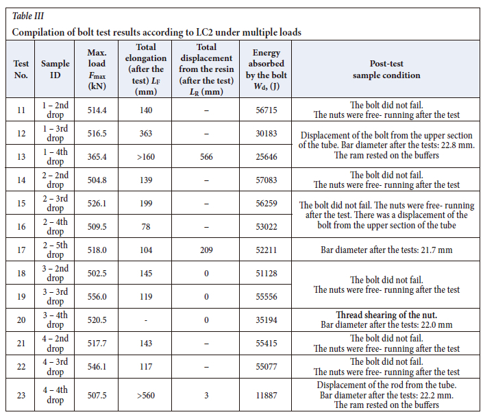
 -
 Similars in Google
Share

 Permalink
Journal of the Southern African Institute of Mining and Metallurgy
On-line version ISSN 2411-9717
Print version ISSN 2225-6253
J. S. Afr. Inst. Min. Metall. vol.123 n.11 Johannesburg Nov. 2023
http://dx.doi.org/10.17159/2411-9717/776/2023
PROFESSIONAL TECHNICAL AND SCIENTIFIC PAPERS
Resistance of yielding rockbolts to multiple impact loads
A. Pytlik; D. O'Connor; D.J. Corbett
Glówny Instytut Górnictwa - Paiistwowy Instytut Badawczy, Zaklad Badail Mechanicznych i Inzynierii Materialowej, Katowice. ORCID: A. Pytlik http://orcid.org/0000-0003-0899-0590. D. O'Connor http://orcid.org/0000-0001-8346-4035. D.J. Corbett http://orcid.org/0000-0002-8534-5344
SYNOPSIS
The resistance of yielding rockbolts to multiple impact loads was tested by means of a drop hammer. The methodology was based on the ASTM D7401-08 standard as well as the requirements specified for rockbolts by Luossavaara-Kiirunavaara Aktiebolag (LKAB - a Swedish mining company) and the Safety In Mines Research Advisory Committee of South Africa (project number GAP 423). During the tests, the loading force and bolt elongation were measured with a sampling frequency of fs = 19.2 kHz. In order to analyse the phenomena involved, the tests were recorded using two independent high-speed video cameras (600 and 1000 frames per second) and one thermal camera (128 frames per second).
The tests demonstrated that all the samples transferred double the gravitational potential energy of Ep = 50.85 kJ from the impact load of mass m = 2825 kg and impact velocity of v = 6.0 m/s without failure. Damage to the bolt-resin contact in the upper anchoring zone of the bolt in the steel tube occurred after subsequent impacts. As a result, the macro-deformed bolt exhibits additional yield, and its operation following the shearing of the resin bond is similar to that of a 'cone bolt'. Only one test resulted in damage to the threaded bolt rod-nut coupling, during the fourth impact; however, no damage to the bolt-resin contact zone was observed.
Keywords: yielding rockbolts, dynamic impact drop test, multiple impact loads, consecutive impacts, thermovision analysis.
Introduction
The necessity of conducting mining operations at increasing depths results in significantly greater hazards related to seismic events, such as rockbursts (strain bursts and fault-slip bursts) (Guntumadugu, 2013; Li, 2017a, 2017b; Li et al., 2019). Dynamic loading, caused by the impact of masses of rock that intrude into a working as a result of a rockburst is particularly hazardous to the mining support and its stability, which is the primary factor determining safety in a working. An intensification of the rockburst phenomenon is observed in deep metalliferous mines (in hard and strong rock), particularly at depths greater than 1000 m, which results in severe intrusion of rocks into the workings (Li, 2017b). Yielding support is often used in order to secure the workings against static and dynamic loading originating from the rock mass. In underground mining, the most commonly employed types of yielding support include:
> Yielding steel arch support (passive) - commonly employed in hard coal mines (Horyl and Sñupárek, 2007; Pytlik, 2020a; Zhao et al., 2015; Sun et al., 2018)
> Yielding rockbolt support (active) - worldwide application, typically in metalliferous mines, for the purposes of rock mass reinforcement under conditions of great rock mass stresses accompanied by rockbursts in hard and strong rock (Li, 2017b)
> Mixed support, e.g. with yielding steel arches and rockbolts - commonly employed in Polish, German, Czech, and Chinese hard coal mines (Pytlik, 2019).
Steel mesh is another important support element for absorbing energy under dynamic loads (Eriksson, 2020), and it is used in combination with both arch support systems and rockbolts. Damage to steel weldmesh typically occurs at an impact energy of about 2 kJ (Villaescusa, 2009; Pytlik, 2015b).
Though no standardized definition or evaluation criteria of a 'yielding support'- can be found, it may be stated that yield is a key property of the support, by which the rock mass surrounding the working can undergo significant deformation (at a minimum support load capacity determined by the designer) with no resulting damage to the support elements. Therefore, compared to standard support, a yielding support operating under identical rock mass deformation and load can be expected to retain its integrity. Consequently, yielding support units improve the stability of a working and increase worker safety. In the case of a yielding steel arch support, the condition of its elements can often be assessed relatively quickly by visual examination or technical means. However, a problem arises in the case of rockbolt support, since the condition of the bolts installed in the rock mass (by means of resin, grout, or expandable anchors) is difficult to determine quickly. A question that is particularly important in the context of rockbursts is: what is the condition of the bolts, and consequently what is the level of safety in the working, not only after the first rock impact, but also following the subsequent impact loading of the bolts? The problem of the maximum rockbolt support deformation (as determined by the designer), which is meant to ensure unobstructed access to and stability of the working, is closely related to this.
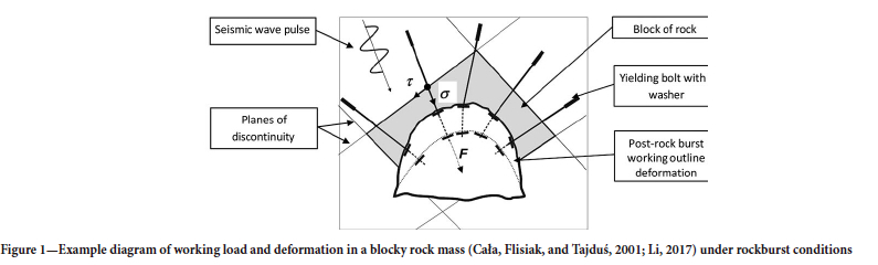
In the case of rockbolt support in a blocky rock mass (Cala, Flisiak, and Tajdus, 2001; Li, 2017b), the dynamic displacement of a loose block of rock into a working may occur during rockbursts. The support units responsible for bearing the load and absorbing the impact energy are tendons, usually in the form of steel bars or cables. Under in-situ conditions, the bolts are subjected to complex states of loading, occurring primarily as a result of tension (normal stress) and shearing (shear stress) (Figure 1). Comparative shear tests of threaded bolts under dynamic loads (Pytlik, 2020b) demonstrated that the bolt's energy absorption capacity was considerably lower than that of bolts subjected exclusively to tension. This is understandable considering that, practically speaking, shearing results only in bolt diameter deformation, and it is the level of deformation that is the primary factor influencing bolt yield. For example, during the shear tests, bolts produced from threaded bars with a core diameter of 21.7 mm (effective bolt rod diameter De = 22.1 mm), formed from steel with a strength of Rm = 830 MPa and elongation of A = 19%, absorbed energy at a level of Wd = 1.269 ± 0.062 kJ. However, during tensile tests under dynamic loading, the same type of bolt can absorb an energy of Wd = 29.5 kJ without failure.
A schematic diagram of a gallery working driven in a blocky rock mass, secured by means of rockbolt support and exposed to the dynamic influence of blocks of rock as a result of rockbursts, is depicted in Figure 1.
Similar problems with maintaining the stability of workings exposed to dynamic loads generated by rockbursts are present in mines all over the world (Li, 2010).
An example of the major problems regarding this issue can be found in ultra-deep gold mines (extraction at a depth of nearly 4000 m) in South Africa (Sengani, 2018). Increasing work safety is possible only by the utilization of rock mass destressing, correct support design, and testing of the support unit technical parameters under laboratory conditions (static and dynamic tests) and underground (static tests).
Rockbolt test methodologies and standards are specified in many countries in Europe, North and South America, and Australia. For example, detailed standardization regarding the mechanical elements of bolts is included in Polish (PN-G-15091:1998 and PN-G-15092:1999), German (DIN 21521 Teil 1:1990 and DIN 21521 Teil 2:1993), USA (ASTM F 432-13, ASTM D 7401-08),
British (BS 7861-1:2007), Canadian (CAN/CSA-M430-90), and South African (SANS 1408:2002) standards. The only example of a standard that specifies the methodology for bolt tests under dynamic loading is ASTM D7401-08, according to which the tensile impact loading of bolts is performed by means of a drop hammer (ram). Tests of bolts under dynamic loading based on ASTM D7401-08 are conducted by internationally renowned laboratories in Australia, Canada, South Africa, and Sweden. There are many publications in the international literature that provide test results from laboratories (Hadjigeorgiou and Potvin, 2007, 2011) such as CANMET-MMSL (Labrie, Doucet, and Plouffe, 2008; Plouffe, Anderson, and Judge, 2008), the Western Australian School of Mines (WASM) (Player, Thompson, and Villaescusa, 2008; Player, Villaescusa, and Thompson, 2008; Potvin, Wesseloo, and Heal, 2010; Villaescusa, 2009), the SRK drop weight test facility (SIMRAC Project GAP 423 (Ortlepp and Stacey, 1998)), and New Concept Mining in Canada and South Africa (Bosman, Cawood, and Berghorst, 2018; Knox and Berghorst, 2018; Knox, Berghorst, and Crompton, 2018; Knox, Berghorst, and de Bruin, 2018) and SINTEF, and the Norwegian University of Science and Technology (NTNU) in Trondheim (Hagen et al., 2020). Recently, the Central Mining Institute in Poland (GIG) has been conducting dynamic tests of bolts according to ASTM D7401-08. The current capabilities of the GIG test facility enable the testing of bolts with a maximum length of 4.0 m by means of an impact mass of m = 6000 kg dropped from a height of 3 m. This makes it possible to load the bolt with an impact energy of Ep= 176.6 kJ and impact velocity of v = 7.67 m/s. Other kinds of tests conducted at the GIG facility include the impact testing of hydraulic props (Pytlik, 2015a, 2018; Prusek et al., 2016), mining chains (Michalak et al., 2012), shaft hoist ropes, and cable bolts (Pytlik, Prusek, and Masny, 2016) with a maximum impact energy of Ep = 500 kJ (m = 20 000 kg, h = 2.5 m).
The above test facilities make it possible to simulate impact loads across broad ranges of impact energy and velocity, which are observed in situ. For example, during tests that were conducted in iron ore mines (Shirzadegan, Nordlund, and Zhang, 2016a, 2016b) belonging to LKAB (Sweden), the measured maximum PPV (peak particle velocity) was 7.5 m/s. Rockburst simulations performed under gold mine conditions (Haile and le Bron, 2001; Milev et al., 2001; Milev and Spottiswoode, 2005) in South Africa also revealed high PPV values, reaching up to 3.3 m/s. Direct and indirect estimates (Ortlepp and Stacey, 1998) of rock ejection velocities range from 3 to 10 m/s or even higher.
This article presents a methodology for the laboratory testing of yielding bolts via dynamic tensile impact loading exerted by means of a drop hammer, and attempts to determine the resistance of yielding rockbolts to multiple impact loads. The methodology is based on ASTM D7401-08 as well as the test methodology and requirements specified for rockbolts by LKAB and the Safety in Mines Research Advisory Committee - Project Number: GAP 423 (Ortlepp and Stacey, 1998). In order to determine the resistance of yielding rockbolts to multiple impact loads, yielding bolts with high load capacity and elongation capability were selected for the tests. The tests adopted a higher impact energy and velocity than the typical values specified for bolts by LKAB (E = 30 kJ and v = 5 m/s). The impact energy during testing was E = 50.85 kJ (drop hammer mass of m = 2825 kg), providing an impact velocity of v = 6 m/s (at a ram free fall height of h = 1.835 m). During the tests, the loading force and the bolt elongation were measured with a sampling frequency of fs = 19.2 kHz. The tests were recorded using two independent high-speed video cameras (600 and 1000 frames per second) and one thermal camera (128 frames per second).
Yielding bolt test methodology using multiple impact loads
The objective of testing yielding bolts under multiple impact loads is to conduct relatively simple and repeatable tests, the results of which could be used by bolt manufacturers and rockbolt support designers, as well as for the purposes of confirming compliance with safety requirements in the process of product certification. The tests make it possible to determine the technical condition of the yielding bolt elements and connections.
The methodology also enables comparison of the load capacity, elongation, and energy absorbed by various types of bolt; the determination of sensitive zones in the tested bolts and zones of thermal energy accumulation; and the definition of the maximum number of impacts that can be sustained beforw damage occurs to the elements of the bolt, the threaded coupling, and the resin anchor.
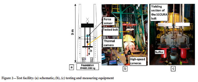
The primary objective of the tests was to determine whether a bolt can be safely utilized in underground mines susceptible to rockbursts, where the support is exposed to a series of loads exerted as a result of roof caving and rockbursts. The test facility is illustrated in Figure 2.
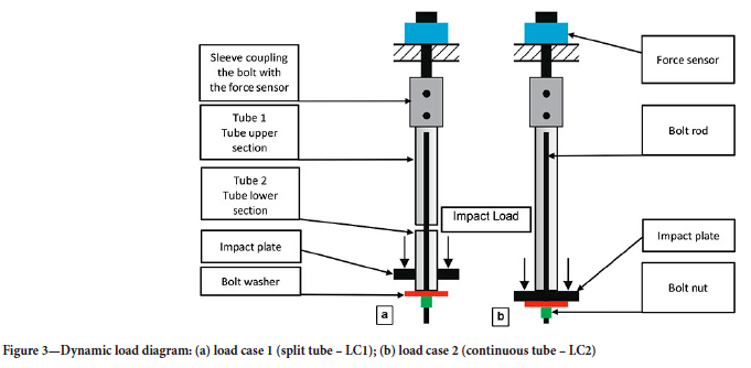
Rams with various masses adapted to the selected impact energy were used during the tests. The bolt test method is based on the free fall of a ram with a mass m from a given height h, giving the selected impact velocity v. The ram strikes the bolt, exerting load upon it according to the two load cases presented in Figure 3.
According to the ASTM D7401-08 standard, bolt impact energy Ep and impact velocity v are calculated from the following formulae:


where
m - ram mass, m = 2825 kg
g - gravitational acceleration, 9.81 m/s2
h - ram height of fall, m.
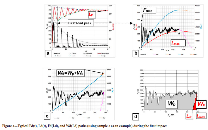
During the test, the impact of a drop mass m against an impact plate initially results in an inelastic collision (leading to bolt elongation), after which the periodic rebounding of the mass from the plate can be observed (Figure 4a), which indicates an elastic collision. This is a typical phenomenon that occurs under real conditions when two bodies undergo an elasto-plastic collision of an intermediate character. The rebound height periodically reached by the drop mass is low enough to have only a slight influence on the degree of bolt deformation. Based on the post-process analysis of paths Fd(t) and Ld(t), which are depicted in a simplified form in Figures 4a and 4b, the following values are determined:
> Maximum load Fmax registered during the test
> Temporary maximum bolt displacement Lmax registered during the first impulse of the force, corresponding to the point of the lowest position of the impact mass, which comes into an elasto-plastic collision with the impact plate (Figure 3)
> Final maximum displacement Lf measured after the test.
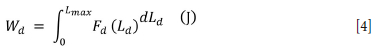
The value of the energy Wd absorbed by the bolt is calculated to determine bolt energy absorption during the test (Figures 4c and 4d). It is a basic parameter that is useful for both comparing different bolts and aiding the rockbolt support design process, as it is calculated and provided in literature by research laboratories for various types of bolts. The total value of the energy Wd absorbed by the bolt, which corresponds to the energy consumed during the elasto-plastic deformation of the bolt bar material (equal to the work done on the deformed bolt) is calculated by integrating the id = f(Ld) path using the following formula (Chrysochoos and Martin 1989; Maj, 2007):

where
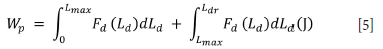
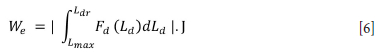
We - energy consumed for the elastic (reversible) deformation. Energy We is released as the bolt is unloaded (path Fdr in Figures 4b and 4c) during the first load impulse (Figure 4a) Wp - energy consumed for the plastic (irreversible) deformation. The total energy Wd absorbed for the deformation is calculated by integrating the Fd = f(Ld) path:
Once the bolt is unloaded as a result of the elasto-plastic rebound of the ram mass (during the first impact), the energy Wp consumed for the plastic deformation is calculated using the following formula:
The absolute value of the second element of Equation [5] corresponds to the energy We consumed for the elastic deformation:
where
Lmax - maximum elasto-plastic elongation of the bolt during the first load peak, corresponding to the lowest position of the ram relative to the facility foundation.
Ldr - plastic bolt elongation after reducing the force from a value of Fdr = f(Lmax) to zero.
By using a high-speed thermal camera it is possible to record the temperature variations of the tube with the grouted bolt rod as well as of the steel rod with a sampling frequency of 128 Hz. Average bolt rod temperature rise ΔTa is calculated from the following formula:
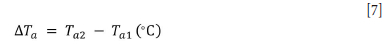
Ta1 - average bolt rod section temperature before the test (°C)
Ta2 - final average bolt rod section temperature after the test (°C)
There are certain technical differences between the methodologies provided by the ASTM D7401-08 standard (2008), LKAB, and SIMRAC, but they share a common method of exerting dynamic loads by means of the free fall of a drop mass.
The ASTM D7401-08 standard (2008) assumes a single dynamic load case in the form of the direct loading of the bolt washer and nut by means of a free falling drop mass. Typical test parameters include an input energy of 16.01 kJ and impact velocity of 5.425 m/s.
The LKAB test methodology, though based on ASTM D7401-08, introduces an additional load case in the form of a bolt mounted in a split tube. The load is exerted indirectly on the bolt by loading the lower section of the tube (according to the LC1 diagram in Figure 3). This makes it possible to test the yielding part of the bolt. Typical requirements adopted by LKAB in terms of the kinetic energy of the load include 19 kJ for a bolt in a continuous tube, 30 kJ for a bolt mounted in a split tube, impact velocity of 5 m/s, and maximum elongation greater than 140 mm for a 2.1 m long bolt.
The methodology adopted by the Safety In Mines Research Advisory Committee of South Africa, described in the GAP 423 project report (Ortlepp and Stacey, 1998), is also based on the principle of the dynamic loading of a bolt by means of a free-falling drop mass. The bolts are grouted directly into steel tubes or into tubes filled with a binding agent simulating rock, to a length of 0.6 to 2.4 m (depending on the type of bolt). Before testing, the bolt is statically loaded with an 820 kg beam, which is then impacted by a ram with a mass of 1048 kg or 2706 kg. The adopted impact velocity is 3-10 m/s. The impact velocity during the test depends on the ram drop height. A single bolt is subjected to multiple impacts until failure. An increase in the force and energy absorbed by the bolt was observed over the course of the subsequent impacts. Typical threaded bolts formed from rebars and smooth bars with a diameter of 16 mm were used during the tests. Furthermore, the authors concluded that the smooth bar bolts absorbed significantly more energy than the rebar bolts, and plastic deformation was uniform along the entire length of the bolt. A partial slip of the bolt from the smooth bar occurred following the failure of the bolt-grout interface, which resulted in the absorption of additional impact energy, while progressive debonding further secured the bolt from rupture.
Test procedure
Secura yielding bolts, which are a threaded bolt variant formed from smooth bars that end with a thread, were selected for the cyclic impact load tests. The mechanical properties of the bar material are the main factor influencing the yield of this bolt. The yielding section of the bolt, formed from a 25 mm diameter smooth bar, is primarily responsible for absorbing impact energy. Cyclic impact load tests performed on the same bolt reveal the bolt's ability to absorb tensile load energy, determine whether there are any indications of imminent failure, and establish how many times a bolt can be loaded before failure. Weak points in the bolt structure and the bolt-grout interface can also be identified based on the tests.
Bolts with yielding sections formed from smooth bars are available on the market, similar to the Secura bolt (Cai, Champaigne, and Kaiser, 2010; Charette et al., 2014; Doucet and Voyzelle, 2012; Guntumadugu, 2013; Li, Stjern, and Myrvang, 2014; Ghorbani et al., 2020; Nguyen, Cai, and Challagulla, 2018; Raju, Mitri, and Thibodeau, 2011; Yokota et al., 2020), such as the cone bolt, D-bolt, Garford solid bolt, and others. This is why the experience gained during the dynamic testing of Secura bolts could be utilized for other types of threaded bolts that are subjected to dynamic loading by means of tensile axial force.
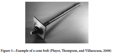
Gaudreau, Aubertin, and Simon (2004) carried out cyclic impact testing on an NTC impact test rig, using impact masses of 750 kg and 1000 kg. During the testing of one of the cone bolt type bolts named MCB, it was found that the bolts would not fail even after four impacts, while the most common reason for failure was rod or nut thread shearing. Tests of various types of bolts under similar conditions were also conducted by Player, Thompson, and Villaescusa (2008) at the Western Australian School of Mines (WASM) and at CANMET - MMSL (2008). Analysis of the tests reveals that cone bolt type bolts (Figure 5) achieve very similar results in terms of the absorption of energy greater than 50 kJ (at a maximum force of over 200 kN and deformation greater than 300 mm) compared to the Secura bolt (yielding section formed from a smooth bar).
This is in line with the test results from numerous laboratories that were compared by Hadjigeorgiou and Potvin (2011) as well as Potvin, Wesseloo, and Heal (2010). The cone bolt mode of operation is similar to conventional two-point anchored bolts as well as other bolts such as Garford bolt, Roofex, Yield-Lok (Li, Stjern, and Myrvang, 2014) and the Secura bolt. This was confirmed by both thermal imaging-assisted tests and geometric bolt measurements carried out after cyclic impact testing, which revealed a uniform deformation of the bolt rod along its length and diameter between the two anchor points: the profiled section.
The t Secura-type bolts, tested are depicted schematically in Figure 6.
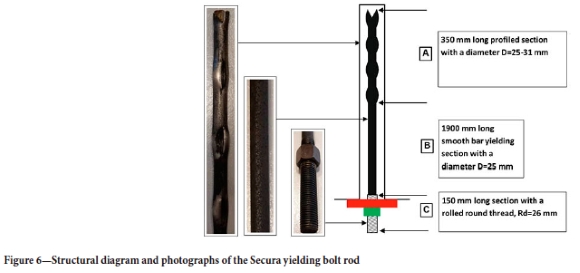
The Secura bolt rod is formed from a smooth bar with a length of L = 350+1900+150 = 2400 mm (profiled section length + yielding section length + thread). Other technical parameters of the bolts and installation are:
> Size: Dia = 25.0 mm diameter smooth bar
> Steel grade: manganese-steel alloy
> Thread specification: DIN 405-26 mm (left-hand thread)
> Hex nut: 36AF × 30H (heat treated)
> Resin: fast-setting resin (at the anchor end of the hole) -colour code green. Minova Africa Lokset resin capsule, 30 mm diameter, Type A; setting time 60 seconds; slow resin (for the balance of the length) - colour code yellow, setting time 5-10 minutes. Minimum shear strength when tested per SANS 1534:2018 is 23 MPa
> Installation: 250-300 r/min rotation (after each installation the produced specimen was left for 1 minute to harden, then removed).
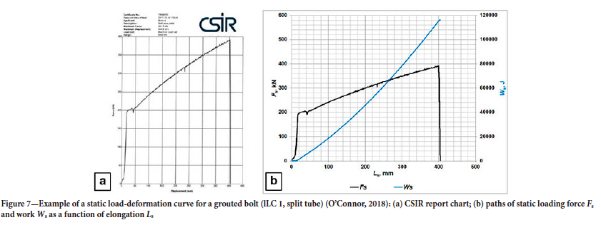
Prior to dynamic testing, the quasi-static load-deformation characteristics of the steel bolts themselves, and of the bolts resin-grouted into steel pipes, were determined by tensile testing at the Mechanical Engineering Laboratory of the South African Council for Scientific and Industrial Research (CSIR). The tests were displacement-controlled at 90 mm/min (O'Connor, 2018). The load-deformation curves of the bolts by themselves and the grouted bolts were quantitatively similar, indicating that the behaviour was dominated by the deformation of the bolts alone, not the relative displacement between the bolts and the resin grout. The results also reveal the good mechanical properties of the rod under static loading as well as a great energy absorption capacity. Example load elongation Fs = f(Ls) and work elongation Ws = f(Ls) paths are presented in Figure 7. During the tests, the maximum force was Fsmax = 391.3 kN, elongation was Lsmax = 404.8 mm, while work until rod rupture was 111 kJ. The diagrams demonstrate that the yield point of the bolt rod (with a length of 1650 mm) is Re = 400 MPa, whereas the ultimate strength reaches a value of Rm = 800 MPa (which is also the point of rod rupture) at a relative elongation of A = 24.5%.
The dynamic bolt testing procedure was as follows.
1. Mount a bolt grouted into a 2.1 m long tube in the test facility (Figure 3a or 3b).
2. Determine the impact energy Ep and the impact velocity v from Equations [1] and [2].
3. Raise the drop mass m to a height h corresponding to the selected impact energy Ep and load velocity v Ep = 50.85 kJ and v = 6.0 m/s - m = 2825 kg, h = 1.835 m (LC 1 and LC 2).
4. Allow the free fall of the mass m from a height h onto:
• the washer of the bolt grouted into a continuous tube
• the washer welded to the tube, 5 cm above its end.
5. Monitor the force F loading the bolt and the bolt displacement L against time, with a sampling frequency of fs = 19.2 kHz. Based on the measurement data, the following paths are determined: Fd = f(t), Ld = f(t), and Fd = f(Ld), which serve as the basis for further analysis and the determination of the energy balance. In order to eliminate noise typical of paths determined under impact loading, the force and elongation paths are subjected to smoothing by means of 2nd- and 4th-order Savitzky-Golay filters.
6. Each bolt rod is tested multiple times (at 10- to 15- minute intervals) until the bolt fails or loses its functional properties, i.e. its load capacity. After the bolt fails, the ram is intercepted by two buffers (equipped with springs and a liquid elastomer) that protect the test facility from damage.
7. After the tests, an opening is made by milling in the upper section of the tube, where the upper section of the bolt -known as the Secura deformed section - is grouted. The displacement LR of the rod within the resin is measured.
The force measurements were carried out by means of a strain gauge sensor (accuracy class 0.5), whereas the displacement measurements were carried out using a laser sensor (resolution of 0.5 mm). The sensors were connected to an HBM MGCplus-type measuring amplifier (accuracy class 0.03), which worked in conjunction with the computer that registered the measurement data.
Each test was recorded using one or two high-speed cameras to register damage-susceptible points on the bolt or the moment and manner of damage. One of the cameras was typically used to record the general view of the entire bolt, while the other was pointed at an area that was particularly susceptible to damage. The videos were recorded at a rate of 600 frames per second (Casio EX-F1) and 1000 frames per second (Sony RX10 IV). Additionally, the tests were recorded using a high-speed thermal camera, the purpose of which was to register the variations in temperature across the entire length of the bolt or at its yielding section. Zones exhibiting significant temperature increases typically represent points where damage, significant deformation (internal friction in the steel bar), or heat accumulation as a result of friction (e.g. at the tube-resin or rod-resin interface) occur. The high-speed thermal camera (Optris PI 230) was operated at a rate of 128 frames per second. Its exchangeable lenses with various angles of view made it possible to record portions of the bolt and the entire bolt.
Results and discussion
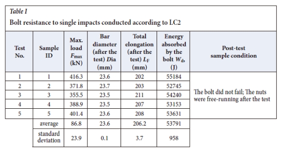
Testing began by investigating the resistance of five bolts to a single impact according to LC 2 (Figure 3). The results are presented in Table I.
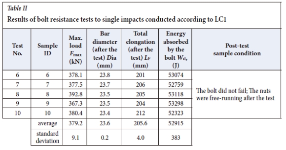
The tests were continued according to l LC 1 using five different bolts, in order to investigate their resistance to a single impact against the yielding section of the bolt (the middle part of the bolt at the junction between the upper and lower parts of the tube). The results are presented in Table II.
Photographs of the bolts after the single impact resistance tests are presented in Figure 8.
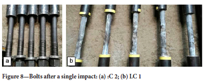
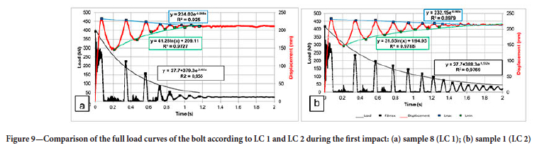
The results exhibit high repeatability for both maximum force and elongation. This was confirmed by visual inspection and photographs of the samples after testing (Figure 8). Also, frame-by-frame analysis of the videos recorded by the high-speed cameras revealed no sensitive zones that would indicate bolt damage. The threaded coupling with the nut, as well as the resin connection with the tube, were not shorn. Although the measured bolt rod diameter was smaller than the initial bolt diameter (pre-test), the diameter deformation was uniform across the entire length of the elongated section. The nut remained free-running after the test. A comparison of the full paths of the tests according to LC1 and LC2 is shown in Figure 9. As can be seen, in the case of LC1 there is a faster damping of the impact energy, which manifests in a smaller number of vibrations and a shorter time for their stabilization. This is influenced by the yielding section B, which has a beneficial effect on the impact energy damping.
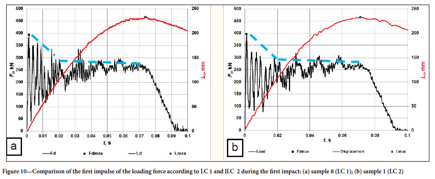
The load and elongation paths were similar for tests conducted according to LC 1 and LC 2. Following the first impulse of the force, the bolt undergoes temporary elongation to Lmax (as a result of elasto-plastic deformation), after which the vibrations of the entire ram-bolt system undergo damping, and the bolt attains a final elongation LF related to the plastic deformation. As an example, a comparison of the first impulse of the force and the elongation during tests of samples 1 and 8 according to LCs 1 and 2 respectively is presented in Figure 10. A significant similarity between the measured load and elongation paths as functions of time can be observed.
During the first load (impact) stage, the force is about 400 kN and the bolt begins elongating until it reaches a temporary maximum value Lmax, which is accompanied by minor sinusoidal damped vibrations of the force within a range of 200 to 300 kN. After the ram-bolt system exceeds the value of Lmax = 30 mm, an elastic rebound of the ram ensues, which results in a decrease in the load to nearly zero, whereas the bolt itself undergoes plastic deformation and minor elasto-plastic vibrations.
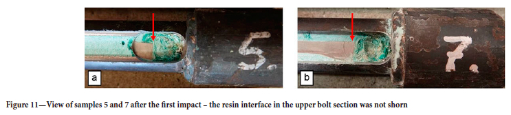
Since the measured characteristics of load and deformation as functions of time were very similar for all of the tests conducted according to LCs s1 and 2, and since no deformations were observed in the upper sections of the tubes, it was inferred that no displacement of the bolt had occurred in the upper section of the tube (i.e. relative to the embedding resin). In order to investigate the bolt-resin interface in the upper section of the tube, longitudinal openings were cut in randomly selected samples (no. 5, 6, and 7). These exposed the upper sections of the bolts (section A). No bolt displacement LR from the resin was found during tests conducted according to LCs 1 and 2 (see Figures 11a and 11b).
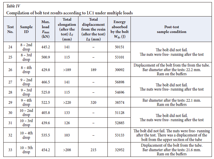
Subsequent impact tests, from 2 up to 5 impacts, were conducted on previously tested samples, using the thermal camera in order to inspect the temperature distribution across the entire length of the tubes into which the bolts were grouted. A compilation of the results is included in Tables III and IV
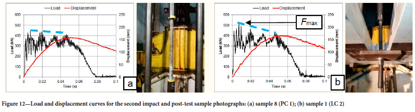
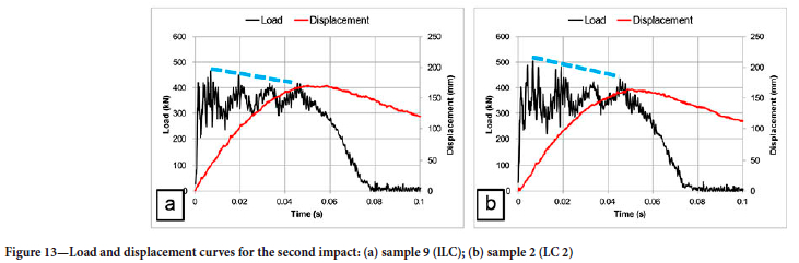
It was observed that, compared to the first bolt impact tests, the force Fmax increased, reaching up to 517.7 kN during the second impact, whereas the final maximum bolt elongation LF decreased to about 140 mm (during the first bolt impact tests, the average elongation LF was about 206 mm). Additionally, no deformation of the tubes into which the bolts were grouted was noted, but there were further deformations of the bolts themselves. All nuts remained free-running after the tests. Figures 12 and 13 present comparisons between the loading force and displacement as functions of time during the second impact for LCs 1 and 2.
During the tests according to LC 1, the maximum loads in the first phase of the impulse were lower compared to the tests according to LC 2 (Figure 3). This was confirmed by the tests conducted on different samples (Figure 13).
Minor sinusoidal damped vibrations of the force within a range of 300 to 400 kN, can be observed on the charts. After the ram-bolt system exceeds the value Lf =170 mm, an elastic rebound of the ram ensues, which results in a decrease in the load to nearly zero, whereas the bolt undergoes plastic deformation and minor elasto-plastic vibrations, similarl to those during the first impact tests.
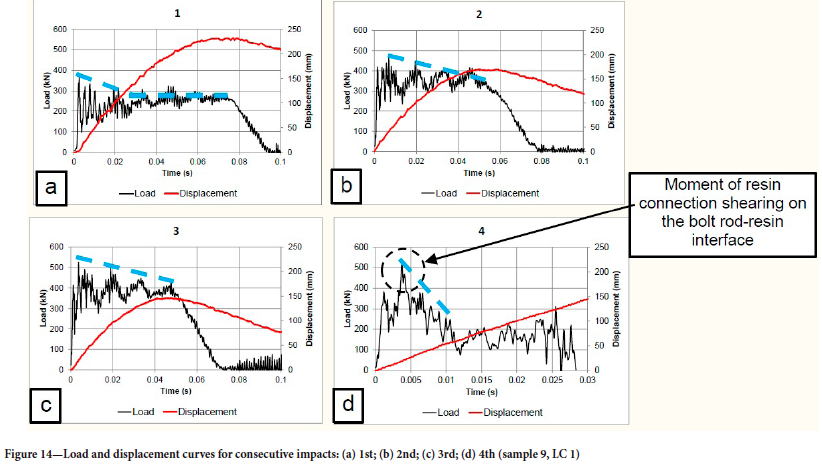
An example comparison of consecutive impact tests is depicted in Figure 14.
Each consecutive impact test conducted on each bolt resulted in increased load and decreased bolt elongation, which can be observed in Figures 14a-c.
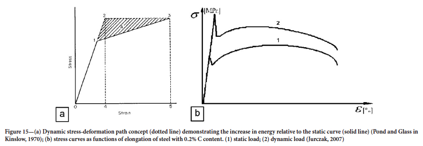
Pioneering work by John Hopkinson and his son Bertram Hopkinson revealed that the dynamic yield point of steel is nearly twice as great as the static yield point. Fundamental tests regarding the phenomena in solids during impact were presented by Taylor (1954) and Campbell (1953). A number of test results were also presented in the book edited by Kinslow (1970). The concept of the dynamic stress-deformation path presented therein by R.B. Pond and C.M. Glass demonstrates the significant increase in the yield point and deformation energy (the crosshatched part marked A) relative to the static curve (Figure 15a). The phenomenon of steel strength increasing together with the rate of elongation is typical (Jurczak, 2007; Kinslow, 1970) and is confirmed in numerous studies. Figure 15b presents example stress curves as functions of elongation of steel with 0.2% C content.
This phenomenon was also described by Ortlepp and Stacey (1998). In the case of sample 9 during the 4th impact, the bolt-resin interface was shorn, which resulted in additional bolt yield and protected the bolt from rupturing. The protective reaction of the bolt was thus confirmed, proving that failure is prevented by the absorption of a part of the impact energy, which is a consequence of the bolt's sliding (Ortlepp and Stacey, 1998).
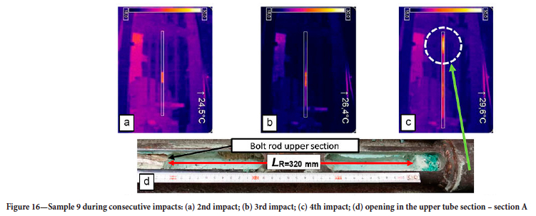
No bolt damage or deformation of the upper section of the tube (the portion of the tube into which the bolt is anchored by the 'Secura' deformations) was observed in bolt tests during the 2nd and 3rd impacts. Deformation of the upper tube section occurred only as a consequence of the 4th impact, which was confirmed by paths of the force as a function of time (Figures 14a, 14c) and by the thermal camera photographs presented in Figure 16.
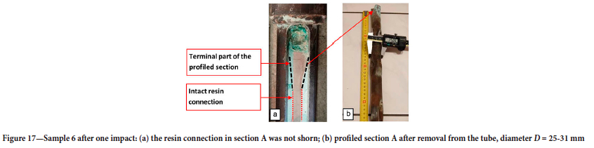
The tests demonstrated that bolts 8 and 9 (LC 1) transferred a load with an impact energy of 50 kJ a maximum of three times without slipping from the upper tube section. By the fourth impact during the testing of bolts 8 and 9, the rods had already undergone displacement inside the tube. Bolt 10 transferred the load twice and underwent displacement in the tube during the third and fourth impacts, whereas by the fifth impact, the rod slipped out of the tube. The paths of load as a function of time and displacement demonstrate that despite slipping out of the tube, the bolt continued to retain a high load capacity. The reason for this is that the rod-grout-tube interface forms a kind of friction connection similar to a wedge (Figure 17), which leads to significant resistance to motion and the emission of great amounts of heat during the displacement of the rod.
Thermal measurements did not reveal any local points of bolt temperature increase that could indicate the beginning of failure. This was confirmed by tests carried out on sample 8. Since the thermal camera utilized a telephoto lens, it was possible to precisely determine the increase and distribution of bolt temperature in the visible part of the yielding section during the second and third impacts. Thermal images taken during the second impact against sample 8 are presented in Figure 18.
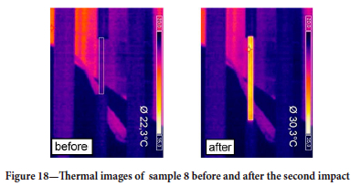
The maximum average temperature increase during testing was Ta = 8.0°C. No points of excess heating were observed along the embedded tube, only uniform heating of the tube as a result of heat emission by the bolt rod from the time of the previous test. The bolt section between tubes 1 and 2 (Figure 3) exhibits uniform heating along its entire length. There is also no 'necking' that would result in a local temperature increase, which would indicate a risk of bolt rupture. Thermal images taken during the third impact against sample 8 are presented in Figure 19.
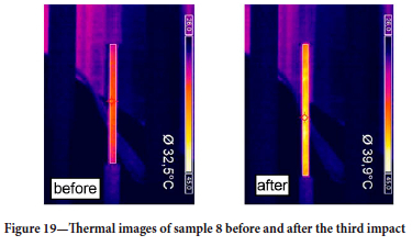
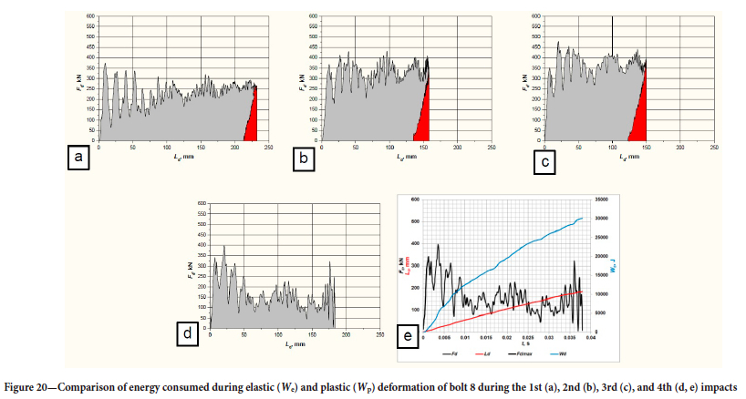
The maximum average temperature increase during testing was Ta = 7.4°C. No points of excess heating were observed along the embedded tube, only uniform heating of the tube as a result of heat emission by the bolt rod from the time of the previous test. The bolt section between tubes 1 and 2 exhibits uniform heating along its entire length, and there is also no 'necking' that would indicate a risk of bolt rupture. Comparisons of the energy We consumed for the elastic deformation and energy Wp consumed for the plastic deformation of bolt 8 during impacts 1 to 4 are presented in the paths displayed in Figure 20.
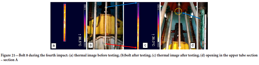
Sample 8 transferred three impacts without bolt failure and shearing of the resin connection in the upper part of the tube embedment. However, the fourth impact resulted in the shearing of the resin connection at the rod-grout interface, which led to the pulling out of the bolt rod (Figure 21).
Analysis of the thermal image (Figure 21c) revealed that after the rod was pulled out of the grout; its upper part exhibited a maximum temperature of Tmax = 26°C, while for the lower part it was Tmax = 36°C, which indicates a clear boundary between the embedded section in tube 1 and the yielding section between tubes 1 and 2. The pulling out occurred approximately 40 ms following impact, and as can be observed, the post-test rod temperature did not increase over this time. There was no further increase in the plasticity of the rod in the yielding section, and the force with which the bolt was pulled out was primarily a result of friction between the sliding rod and the grout.
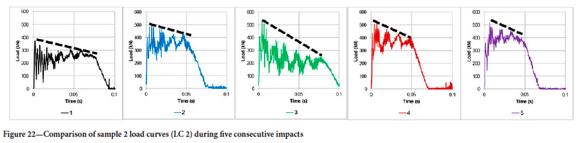
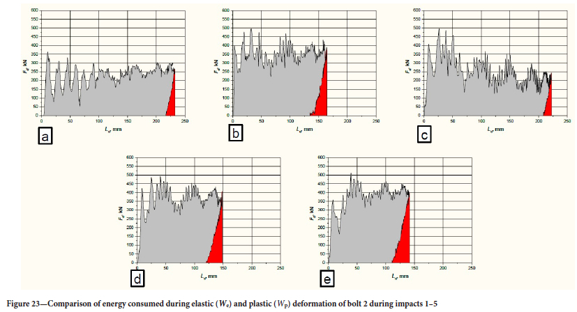
Another instance of a bolt subjected to multiple impact loads is depicted in Figure 22, presenting sample 2, which was subjected to load tests according to lLC 2. The compilation includes five test paths during impacts 1 to 5.
Figure 23 presents five Fd Ld paths obtained during the tests after impacts 1 to 5.
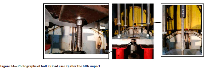
The bolt-resin interface was shorn during the third impact, but the bolt retained its operational properties and was still capable of transferring the load during the fourth and fifth impacts. No breaking of the bolt continuity or shearing of the bolt thread and nut were observed after testing (Figure 24).
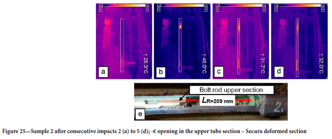
However, heating of the upper section of the bolt rod was observed in thermal images. Heating began during the third impact and progressed over the fourth and fifth impacts, which can be seen in Figures 25a-d. At the end of the test series, the tubes were opened in the upper sections. Figure 25e presents a section of the tube with a visible bolt displacement of LR = 209 mm.
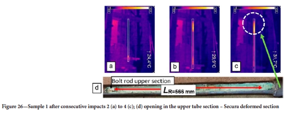
Sample 1 exhibited a similar behaviour, which can be observed in the thermal images depicted in Figures 26a-c and in the photograph of the milled-open tube after testing (Figure 26d).
The only instance of damage to a mechanical element of the bolt was noted during a test conducted on sample 3. The bolt transferred three impact loads without damage, but the thread on the bolt-nut interface was sheared during the fourth impact, which resulted in a sudden drop in force and a loss of the bolt's functional quality. The paths of these tests are depicted in Figure 27.
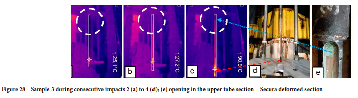
For the same sample, the thermal images in Figures 28a-c show no bolt displacement in the upper section, as indicated by the absence of temperature increase in the bonding zone. An opening cut in the upper tube section also revealed no bolt displacement, and the resin connection was intact (Figure 28e). Despite the significant elongation and constriction of the bolt, bolt rod rupture did not occur (Figure 28d). The measured diameter of the non-threaded part of the bolt rod averaged about 22.0 mm (the pre-test diameter was 25.0 mm). The diameter was practically uniform across the entire section of the bolt rod, and no characteristic local constriction in the form of a 'neck' that would indicate the beginning of bolt rupture was observed.
However, it is likely that the shearing of the bolt thread in the nut was due to the reduction in the diameter of the thread, which after the test measured approximately 24.9 mm. There was no bolt yield resulting from the displacement of the bolt in the upper tube section. This (often unfavourable) phenomenon, which leads to a loss of load capacity due to shearing of the bolt rod-resin connection, in this case gives the bolt further yielding potential, the effects of which are similar to a friction coupling. It can be observed that the style of the Secura bolt macro-deformations initiates the formation of a kind of wedge, the functionality of which is similar to that of a 'cone bolt'.
We suspect that the behaviour of the Secura deformed section (A) as a frictional yielding element can only occur if the steel has first undergone internal deformation. The reduction in the diameter of the steel results in debonding from the resin and ensures that all the load is applied to the (short) resin interface in the Secura deformed section. If the steel did not decrease in diameter first, it would still exhibit good contact with the resin over the entire length of the bolt, which would probably result in rupture of the bolt. Earlier-generation yielding bolts, such as the cone bolt, that relied on relative movement between an anchoring section of the bolt and the surrounding grout, incorporated a debonding layer over most of the length of the bolt.
Summary and conclusions
The Secura-type yielding rockbolts transferred double the gravitational potential energy Ep = 50.85 kJ from the impact of a load of mass m = 2825 kg at an impact velocity v = 6.0 m/s without failure. Damage to the bolt-resin interface in the bonding zone occurred only as a result of multiple impacts.
The test methodology confirmed the rupture of the resin interface, both on the basis of bolt force and elongation paths as functions of time, as well as the analysis of videos recorded by a high-speed thermal camera. Only one test (test no. 20, sample 3) resulted in damage to the threaded bolt-nut coupling on the fourth impact. Since during all the remaining tests the bolts retained their functionality and were capable of continued impact load transfer, the evaluation of the test results should be given more thought. Additional bolt yield due to the displacement of the bolt's deformed section in relation to the resin can be beneficial, resulting in the formation of a kind of tapered frictional coupling in the upper section of the opening for bolt installation.
The tests also confirmed the findings of Taylor (1954) and Taylor and Tadros (1956), who compared such factors as the static and dynamic stress- deformation characteristics of soft steel (0.17% C), medium-carbon steel (0.31% C), and silico- manganese (SiMn) alloy steel with a carbon content of 0.55%. Their tests also utilized the dynamic impact drop method to exert dynamic loading, while the dynamic yield point was achieved over a time of 0.18 to 1 ms. All the tests exhibited increases in dynamic yield point together with shorter loading times, and an explanation for this phenomenon can be found in the theory of dislocation formation in steel under dynamic loads (Campbell, 1953). There is insufficient time for these dislocations to move, which inhibits deformation and thereby results in an increased yield point during the rapid build-up of stress.
In the future, yielding bolt tests under multiple impact loads should be performed for different mechanical configurations of the bolts and at various values of energy and impact velocity. It is envisaged that these tests will investigate the shear strength and adhesion of the resins and grouts under dynamic impact loading.
Acknowledgements
The authors would like to thank Mr Dariusz Modliński and Mr Tadeusz Wosik of MINOVA ARNALL Sp. z o.o. for their assistance in preparing the test facility and the samples for testing, as well as their valuable advice concerning the structure of the test facility.
References
ASTM D7401-08. Standard test methods for laboratory determination of rock anchor capacities by pull and drop tests. ASTM International. West Conshohocken, PA. [ Links ]
ASTM F432-13. Standard specification for roof and rock bolts and accessories. ASTM International, West Conshohocken, PA. [ Links ]
Busman, K., CAWOOD, M., and Berghorst, A. 2018. Relationship between energy per impulse and dynamic capacity of a rockbolt. New Concept Mining. https://www.ncm.co.za/downloads/papers_presentations/Relationship_between_energy_per_ impulse_&_dynamic_capadty_of_a_rockbolt_06.pdf [accessed 27 May 2019] [ Links ]
BS 7861-1. 2007. Strata reinforcement support system components used in coal mines - Part 1: Specification for rockbolting. British Standards Institution, London. [ Links ]
Cala, M., Flisiak, J., and Tajduś, A. 2001. Mechanizm wspólpracy kotwi z górotworem o zróznicowanej budowie. [The mechanism of interaction between anchors and a rock mass with diverse construction]. Instytut Gospodarki Surowcami Mineralnymi i Energią PAN, Kraków. [ Links ]
Cai, M., Champaigne, D., and Kaiser, P.K. 2010. Development of a fully debonded cone bolt for rockburst support. Deep Mining 2010: Proceedings of the Fifth International Seminar on Deep and High Stress Mining. Van Sint Jan, M. and Potvin, Y. (eds). Australian Centre for Geomechanics, Perth. pp. 392-342. [ Links ]
CAN/CSA-M430-90. Roof and rock bolts, and accessories. Canadian Standards Association, toronto. [ Links ]
Charette, F.C., Hyett, A.J., Voyzelle, B., and Anderson, T. 2014. Load-deformation behaviour of a deformable rockbolt and accessories under dynamic loading. Proceedings of the Seventh International Conference on Deep and High Stress Mining. Australian Centre for Geomechanics, Perth. pp. 253-262. [ Links ]
Chrysochoos, A. and Martin, G. 1989. Tensile test microcalorimetry for thermomechanical behaviour law analysis. Materials Science and Engineering A, vol. 108. pp. 25-32. [ Links ]
DIN 21521.1990. Teil 1 - Gebirgsanker für den Bergbau und den Tunnelbau -Begriffe. [German Standard: Rock bolts for mining and tunnelling; terms]. German Institute for Standardization, Berlin. [ Links ]
DIN 21521:1993. Teil 2 - Gebirgsanker für den Bergbau und den Tunnelbau - Allgemeine Anforderungen für Gebirgsanker aus Stahl - Prüfungen, Prüfverfahren. [German Standard: Rock bolts for mining and tunnel support; general specifications for steel-bolts; tests, testing methods]. [ Links ]
Doucet, C. and Voyzelle, B. 2012. Technical information data sheets. CanmetMINING, Ottawa. https://www.workplacesafetynorth.ca/sites/default/files/resources/CanmetMINING-Technical-Data-Sheets-September-2012_1.pdf [ Links ]
Eriksson, F. 2020. Assessment of static performance of LKAB's welded mesh: Laboratory testing and analysis. Master's thesis, Luleâ University of Technology. [ Links ]
Gaudreau, D., Aubertin, M., and Simon, R. 2004. Performance assessment of tendon support systems submitted to dynamic loading. École polytechnique de Montréal. [ Links ]
Ghorbani, M., Shahriar, K., Sharifzadeh, M., and Masoudi, R. 2020. A critical review on the developments of rock support systems in high stress ground conditions. International Journal of Mining Science and Technology, vol. 10, no. 5. pp. 555-572. [ Links ]
Guntumadugu, D.R. 2013. Methodology for the design of dynamic rock supports in burst prone ground. Doctoral dissertation, McGill University. [ Links ]
Hagen, S.A., Larsen, T., Berghorst, A., and Knox, G. 2020. Full-scale rockbolt testing in the laboratory: Analysis of recent results. Journal of the Southern African Institute of Mining and Metallurgy, vol. 120, no. 1. pp. 1-6. [ Links ]
Haile, A.T. and Le Bron, K. 2001. Simulated rockburst experiment - evaluation of rock bolt reinforcement performance. Journal of the South African Institute of Mining and Metallurgy, August 2001. pp. 247-252. [ Links ]
Hadjigeorgiou, J. and Potvin, Y. 2007. Overview of dynamic testing of ground support. Proceedings of the Fourth International Seminar on Deep and High Stress Mining. Australian Centre for Geomechanics, Perth. pp. 349-371. [ Links ]
Hadjigeorgiou, J. and Potvin, Y. 2011. A critical assessment of dynamic rock reinforcement and support testing facilities. Rock Mechanics and Rock Engineering, vol. 44, no. 5. pp. 565-578. [ Links ]
Horyl, P. and Sñupárek, R. 2007. Behaviour of steel arch supports under dynamic effects of rockbursts. Mining Technology, vol. 116, no. 3. pp. 119-128. [ Links ]
Jurczak, W. 2007. Wplyw prȩdkości odksztalcenia na wlaściwości mechaniczne stopu AlZn5Mg2CrZr i stali kadlubowej kat. A. [Investigations into mechanical properties of samples of AlZn5Mg2CrZr alloy and hull steel of typical strength cat. A] Akademia Marynarki Wojennej im. Bohaterów Westerplatte. Zeszyty Naukowe Akademii Marynarki Wojennej, vol. XLVIII, no. 4. pp. 37-47. [ Links ]
Kinslow, R. (ed.) 1970. High-Velocity Impact Phenomena. Academic Press, New York and London. [ Links ]
Knox, G. and Berghorst, A. 2018. Increased agility for the research and development of dynamic roof support products. New Concept Mining, Johannesburg. pp. 1-6. https://www.ncm.co.za/downloads/papers_presentations/Knox_Berghorst-2018-Increased_agility_for_the_research_and_development_of_dynamic_roof_support_products.pdf [accessed 27 May 2019] [ Links ]
Knox, G., Berghorst, A., and Crompton, B. 2018. The relationship between the magnitude of impact velocity per impulse and cumulative absorbed energy capacity of a rock bolt. AusRock 2018: Proceedings of the Fourth Australasian Ground Control in Mining Conference, Sydney, NSW, 28-30 November 2018. Australasian Institute of Mining and Metallurgy, Melbourne. pp. 160-169. https://www.ncm.co.za/downloads/papers_presentations/Knox_Crompton_Berghorst(2018)-The_relationship_between_the_magnitude_of_impact_ velocity_per_impulse_&_cumulative_absorbed_energy_capacity_of_a_rock_bolt-Paper.pdf [accessed 27 May 2019] [ Links ]
Knox, G., Berghorst, A., and de Bruin, P. 2018. An empirical comparison between new and existing laboratory-based dynamic sample configurations. Caving 2018. Proceedings of the Fourth International Symposium on Block and Sublevel Caving. Potvin, Y. and ]Jakubec, J. (eds). Australian Centre for Geomechanics, Perth. pp. 775-786. https://www.ncm.co.za/downloads/papers_presentations/Knox_Berghorst_DeBriun_2018_An_empirical_comparison_between_ new&existing_laboratory-based_dynamic_sample_configurations- Paper.pdf [accessed 27 May 2019] [ Links ]
Labrie, D., Doucet, Ch., and Plouffe, M. 2008. Design guidelines for the dynamic behaviour of ground support tendons. Phase I and II. CANMET-MMSL, Val-d'Or, Quebec. [ Links ]
Li ,C.C. 2017a. Rockbolting: Principles and Applications. Butterworth-Heinemann. [ Links ]
Li, C.C. 2017b. Principles of rockbolting design. Journal of Rock Mechanics and Geotechnical Engineering, vol. 9, no. 3. pp. 396-414. [ Links ]
Li, C.C. 2010. Field observations of rock bolts in high stress rock masses. Rock Mechanics and Rock Engineering, vol. 43, no. 4. pp. 491-496. [ Links ]
Li , C.C., Mikula, P., Simser,, B., Hebblewhite, B., Joughin, W., Feng, X., and Xu, N. 2019. Discussions on rockburst and dynamic ground support in deep mines. Journal of Rock Mechanics and Geotechnical Engineering, vol. 11, no. 5. pp. 1110-1118. [ Links ]
Li, C.C., Stjern, G., and Myrvang, A. 2014. A review on the performance of conventional and energy-absorbing rockbolts. Journal of Rock Mechanics and Geotechnical Engineering, vol. 6, no. 4. pp. 315-327. [ Links ]
Maj, M. 2007. Wplyw kierunku wstçpnego odksztalcenia na proces magazynowania energii w polikrysztalach. [Influence of the initial deformation direction on the process of energy storage in polycrystals]. Doctoral dissertation, Department of Mechanics of Materials and Biomechanics, Institute of Fundamental Technological Research of the Polish Academy of Sciences, Warsaw. http://www.ippt.pan.pl/_download/doktoraty/Maj_doktorat.pdf [ Links ]
Michalak, M., Nürzyńska, K., Pytlik, A., and Pacześniowski, K. 2012. Analysis of deformation of mining chains based on motion tracking. Proceedings of the International Symposium on Visual Computing, San Diego, CA, 3-5 October. Springer, Berlin, Heidelberg. pp. 588-596. [ Links ]
Milev, A.M. and Spottiswoode, S.M. 2005. Strong ground motion and site response in deep South African mines. Journal of the South African Institute of Mining and Metallurgy, vol. 105, August. pp. 515-524. [ Links ]
Milev, A.M., Spottiswoode, S.M., Rorke, A.J., and Finnie, G.J. 2001. Seismic monitoring of a simulated rockburst on a wall of an underground tunnel. Journal of the South African Institute of Mining and Metallurgy, vol. 101, August. pp. 253-260. [ Links ]
Nguyen, B., Cai, M., and Challagulla, K. 2018. Finite element analysis of modified conebolt under static and dynamic loadings. Proceedings of the Canadian Society for Mechanical Engineering International Congress 2018, Toronto, 27-30 May. https://yorkspace.library.yorku.ca/server/api/core/bitstreams/50802b4b-b05f-4c3e-9696-25a70d5581fe/content [ Links ]
O'Connor, D. 2018. Development and testing of a yielding rock bolt system. Minova Africa, Alberton, South Africa. [ Links ]
Ortlepp, W.D. and Stacey ,T.R. 1998. Dynamic loading of rockbolt elements to provide data for safer support design. Project no. GAP 423. Safety in Mines Research Advisory Committee, Johannesburg. [ Links ]
Player, J.R., Thompson, A.G., and Villaescüsa E. 2008. Dynamic testing of reinforcement systems. Proceedings of the 6th International Symposium on Ground Support in Mining and Civil Engineering Construction, Cape Town, 30 March-3 April. Southern African Institute of Mining and Metallurgy, Johannesburg. pp. 597-622. [ Links ]
Player, J., Villaescüsa, E., and Thompson, A.G. 2008. An examination of dynamic test facilities. Proceedings of the 2008 Australian Mining Technology Conference: Smart Technologies for Sustaining the Minerals Boom. Twin Waters, Queensland, 16-18 September 2008. Australasian Institute of Mining and Metallurgy,. Melbourne. https://www.minegeotech.com.au/wp-content/uploads/2020/08/2_DOCO.pdf [ Links ]
Plouffe, M., Anderson, T., and Judge. K. 2008. Rock bolt testing under dynamic conditions at CANMET-MMSL. Proceedings of the 6th International Symposiumon Ground Support in Mining and Civil Engineering Construction, Cape Town, 30 March-3 April. Southern African Institute of Mining and Metallurgy, Johannesburg. pp. 581-596. [ Links ]
PN-G-15091.1998 Kotwie górnicze. Wymagania. [Polish Standard: Rock bolts. Requirements]. Polski Komitet Normalizacyjny, Warszawa. [ Links ]
PN-G-15092.1999 Kotwie górnicze. Badania. [Polish Standard: Rock bolts. Testing]. Polski Komitet Normalizacyjny, Warszawa. [ Links ]
Potvin, Y., Wesseloo, J., and Heal, D. 2010. An interpretation of ground support capacity submitted to dynamic loading. Mining Technology, vol. 119, no. 4. pp. 233-245. [ Links ]
Prusek, S., Masny, W., Lubosik, Z., and Pytlik, A. 2016. Support performance in conditions of dynamic load. Proceedings of the 24th World Mining Congress, Rio de Janeiro. Instituto Brasileiro de Mineração. pp. 427-439. [ Links ]
Pytlik, A. 2015a. Process characteristics of hydraulic legs equipped with safety valves at dynamic load caused by a mining tremor. Archives of Mining Sciences, vol. 60, no. 2. pp. 595-612. [ Links ]
Pytlik, A. 2015b. Graniczne wartości obciążenia dynamicznego powodujące niszczenie okladzin górniczych. [Limit values of dynamic load causing destruction of mining lining]. Przeglqd Górniczy, vol. 71, no. 5. pp. 78-84. https://www.infona.pl/resource/bwmeta1.element.baztech-cf8f339e-8866-4c0f-b7c4-eaeddd1ba643 (pobrany 07.11.2020 [ Links ]
Pytlik, A. 2018. Tests on hydraulic props equipped with yield valves at dynamic load modelling a rock burst. Archives of Mining Sciences, vol. 63, no. 2. pp. 477-489. [ Links ]
Pytlik, A. 2020a. Experimental studies of static and dynamic steel arch support load capacity and sliding joint temperature parameters during yielding. Archives of Mining Sciences, vol. 65, no. 3. pp. 469-491. [ Links ]
Pytlik A. 2020b. Comparative shear tests of bolt rods under static and dynamic loading. Studia Geotechnica et Mechanica, vol. 42, no. 2. pp. 151-167. [ Links ]
Pytlik, A. 2019. Comparative bench testing of steel arch support systems with and without rock bolt reinforcements. Archives of Mining Sciences, vol. 64, no. 4. pp. 747-764. [ Links ]
Pytlik, A., Prusek, S., and Masny W. 2016. Methodology for laboratory testing of rockbolts used in underground mines under dynamic loading conditions. Journal of the Southern African Institute of Mining and Metallurgy, vol. 116, no. 12. pp. 1101-1110. [ Links ]
Raju, D., Mitri, H., and Thibodeau, D. 2011. Mine safety enhancement by designing dynamic rock supports. Procedia Engineering, vol. 26, no. 1. pp. 591-1. [ Links ]
SANS 1408: 2002. Mechanical components for tendon based rock support systems. South African Bureau of Standards, Pretoria. [ Links ]
Sengani, F. 2018. Trials of the Garford hybrid dynamic bolt reinforcement system at a deep level gold mine in South Africa. Journal of the Southern African Institute of Mining and Metallurgy, vol. 118m no. 3. pp. 289-296. [ Links ]
Shirzadegan, S., Nordlünd, E., and Zhang, P. 2016a. In-situ dynamic testing of rock support at LKAB Kiirunavaara mine. Proceedings of the 8th International Symposium on Ground Support in Mining and Underground Construction, Luleå University of Technology, Sweden. Nordlund, E., Jones, T.H., and Eitzenberger, A. (eds). 12 pp. https://pdfs.semanticscholar.org/0079/c003ea173860a989c74a337c428ab14c5ee5.pdf [accessed 27 May 2019] [ Links ]
Shirzadegan, S., Nordlünd, E., and Zhang, P. 2016b. Large scale dynamic testing of rock support system at Kiirunavaara underground mine. Rock Mechanics and Rock Engineering, vol. 49, no. 7. pp. 2773-2794. [ Links ]
Sun, X., Wang, L., Lu, Y., Jiang, B., Li, Z., and Zhang, J. 2018. A yielding bolt - grouting support design for a soft-rock roadway under high stress: a case study of the Yuandian No. 2 coal mine in China. Journal of the Southern African Institute of Mining and Metallurgy, vol. 118, no. 1. pp. 71-82. [ Links ]
Taylor, D.B.C. 1954. The dynamic straining of metals having definite yield points. Journal of the Mechanics and Physics of Solids, vol. 3, no. 1. pp. 38-46. [ Links ]
Taylor, D.B.C. and Tadros, A.Z. 1956. Tension and torsion properties of some metals under repeated dynamic loading (impact). Proceedings of the Institution of Mechanical Engineers, vol. 170, no. 1. pp. 1039-1054. [ Links ]
Villaescüsa, E. 2009. Ground support research at the WA School of Mines. International Journal of the JCRM, vol. 5, no. 1. pp. 1-10. [ Links ]
Yokota, Y., Zhao, Z., Nie, W., Date, K., Iwano, K., Koizumi ,Y., and Okada, Y 2020. Development of a new deformation- controlled rock bolt: Numerical modelling and laboratory verification. Tunnelling and Underground Space Technology, vol. 98. 103305. [ Links ]
Zhao, Y., Liu ,N., Zheng, X., and Zhang, N. 2015. Mechanical model for controlling floor heave in deep roadways with U-shaped steel closed support. International Journal of Mining Science and Technology, vol. 25, no. 5. pp. 713-720. [ Links ]
 Correspondence:
A. Pytlik
Email: apytlik@gig.eu
Received: 23 Jan. 2019
Revised: 16 Mar. 2020
Accepted: 3 Nov. 2023
Published: November 2023

