


Servicios Personalizados
Articulo
 Inglés (pdf)
 Articulo en XML
 Referencias del artículo
Indicadores

Links relacionados
-
 Citado por Google
 -
 Similares en Google
Compartir

 Permalink
Journal of the Southern African Institute of Mining and Metallurgy
versión On-line ISSN 2411-9717
versión impresa ISSN 2225-6253
J. S. Afr. Inst. Min. Metall. vol.123 no.10 Johannesburg oct. 2023
http://dx.doi.org/10.17159/2411-9717/2308/2023
PROFESSIONAL TECHNICAL AND SCIENTIFIC PAPERS
Structural frame analysis of an electrically powered robotic subsea dredging crawler under static loading conditions
M.O. Ojumu*; A.K. Raji
Faculty of Engineering and the Built Environment at the Cape Peninsula University of Technology. ORCID: M.O. Ojumu: http://orcid.org/0000-0003-4318-1115
SYNOPSIS
Robotic subsea dredging crawlers are dynamically and remotely controlled vehicles that are used for deep sea mining and recovery operations. These exploration machines are released from a mother ship and move around on the ocean floor using tracks. Current ocean crawlers such as the MK3 ROST are hydraulically powered. In this paper we develop a scaled-down model for simulating and performing static loading analysis of an electrically powered robotic subsea dredging crawler (EPRSDC). The modeling, simulation, and analysis were carried out using modelling software from Solidworks. The structural frame was assembled using the Tetrix max robotics kit. The kit's structural components were produced from 1050 aircraft-grade aluminum. The results were used in optimizing and for considering other materials, and the to identify specific areas to be reinforced in future crawler designs.
Keywords: static loading, subsea crawler, NI-myRIO, hydraulic crawler, ocean crawler, electrically powered,dredging crawler.
Introduction
In recent years, oceanic dredging crawlers have emerged as a rapidly expanding category of offshore excavation machinery on a global scale. The upswing in demand for marine-based natural resources, including gold, diamonds, iron ore, silver, and aluminium, has generated heightened interest in deep-sea exploration for commercial mining ventures. A subsea oceanic dredging crawler serves as a pivotal apparatus for exploration and sample retrieval. As depicted in Figure 1, a crawler is designed to descend to the sea bed, where it propels itself by traction utilizing either wheels or tracks. The crawler is typically linked to a surface vessel by cables, through which it receives power and control instructions, and which provide a video feed to surface.

In the sea floor mining, extraction encompasses the excavation and recovery of minerals, along with the associated waste material (undersea gravels). These undersea gravels constitute a longstanding amalgamation, primarily consisting of 96.5% water, 2.5% salts, and a small fraction of various other constituents, including dissolved inorganic and organic compounds, particulates, and a limited quantity of atmospheric gases. According to IMDH Group (2016), there has been a noteworthy surge in the demand for metals, thus catalysing heightened interest in deep-sea exploration and commercial mining activities. Dredging crawlers are not only finding valuable applications within mining contexts but are also being deployed for tasks such as subsea tank cleaning operations, subsea photography, as well as providing support for pipeline installations, inspections, and facilitating bio-investigations in oceanic research. Extensive research has been carried out on underwater robotic systems and associated sensing technologies. Chutia, Kakoty, and Deka (2017) reviewed the history of underwater robotics, advances in underwater robot navigation and sensing techniques, and their applications in sea floor exploration.
As illustrated in Figure 1, oceanic dredgers are driven by a hydraulic system to impart operational torque for both the suction arm and track movement. The vehicle is equipped with a primary dredging pump, linked to a riser responsible for material conveyance to the ship's processing unit.
Pioneering work by researchers such as Lloyd-Smith and Immig BAppSc, (2018) introduced a conceptualization of a dredging robot featuring material transport mechanisms. This robot employs a compact vacuum head for sea bed excavation, offering a depth range of 1-50 m. Autonomous control is achieved through waterproof cables, enabling forward/backward and clockwise/counterclockwise movements. The authors emphasize the necessity of fortifying the diving capacity associated with the suction sludge recovery system, which directs sludge through a high-pressure pump to the processing unit via a robust pipeline. The researchers underscore the critical importance of ensuring the structural integrity of subsea equipment, as uneven terrain may induce deformation over time, potentially resulting in costly losses due to structural failures during recovery.
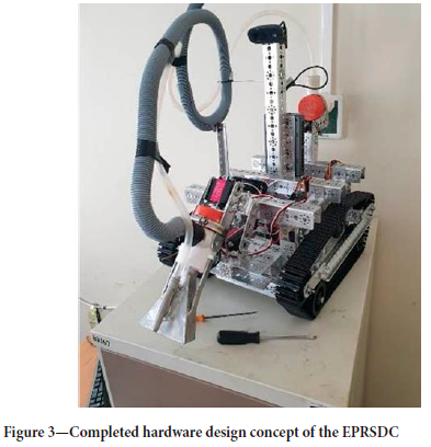
Following our investigation, the electrically powered robotic subsea dredging crawler (EPRSDC) was engineered with a chassis frame serving as the foundational structural element. This frame bears the total operational payload of approximately 8.173 lg. Affixed to the frame (as depicted in Figure 3) are integral components, including a pressure pump, dredging pump, cameras, two 12 V Torquernado motors, three servo motors, motor controllers, servo motor controllers, tank track chains, and the venturi dredging pump unit. The chassis is designed for robustness for navigating diverse environmental conditions and to withstand all applied forces during experimental trials. Materials exhibiting high-performance characteristics suitable for marine applications are under consideration for the construction. The frame drive system incorporates four front wing arms to achieve an angular wheel configuration. Additionally, elements such as tank tread chains, tank tread idler wheels, tank tread sprockets, bronze bushings, motor hubs, and channels of various dimensions were utilized in the assembly of the drive system. These components collectively constitute the primary structural support for the undercarriage frame, facilitating the rolling motion of the track drive. Most other components are located on the boom arm.
This paper aims at providing an in-depth analysis of the potential implications arising from the application of the EPRSDC's structural static compressive force. The swift progression of electrical autonomous components, encompassing waterproofed electric motors, microcontrollers, and the utilization of LabVIEW for microcontroller programming, has significantly streamlined the management of electrical equipment. This integrated system has played a pivotal role in mitigating both oceanic and atmospheric pollution. In the foreseeable future, as an increasing number of structural platforms are orchestrated through algorithmic control for robust oceanic operations, a notable upswing in commercial production can be anticipated, contributing to the reduction of atmospheric pollutants, both on terrestrial and maritime fronts. The international market is currently witnessing heightened demand for offshore autonomous controllers and electrical robots, aligning with evolving customer preferences.
In this study, we employ finite element analysis, specifically leveraging SOLIDWORKS 2019, to evaluate stress distribution across the structural framework design. This step is paramount in making cost-effective enhancements prior to the manufacturing phase. We begin by introducing the three-dimensional design of the EPRSDC's structural frame.
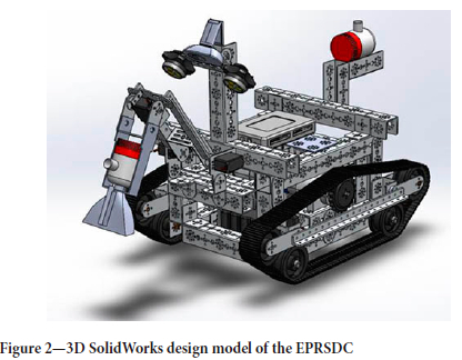
As shown in Figure 2, the EPRSDC was modelled utilizing the SolidWorks student version 2019. This software proved instrumental in fine-tuning individual components prior to the final assembly of the design. Notably, this design exhibits scalability, rendering it suitable for large-scale industrial production of the EPRSDC. In the case of this downscaled prototype, SolidWorks mates were judiciously employed to accurately position all electronic elements, yielding a realistic 3D representation of the model.
Moreover, the software facilitated the seamless integration of the three undercarriage systems of the crawler. It is imperative to utilize computer-aided design (CAD) software in the formulation of a robot's structural and hardware elements. This approach affords complete autonomy and adaptability throughout the developmental trajectory, spanning from conceptualization to the manufacturing phase.
As shown in Figure 3, the crawler concept design was fabricated in strict adherence to the modelled specifications. The utilization of a three-dimensional design framework facilitated dynamic manipulation of individual components, providing enhanced insight into the visual clarity and structural coherence of the final manufactured model. The model was intentionally configured with a 45-degree angular inclination to seamlessly accommodate the integration of multiple sensors and hardware attachments, as exemplified in the illustration.
Literature review
Yang et al., (2012) performed a detailed examination of hydraulic excavator design, elucidating their diverse applications encompassing mining, construction, and forestry contexts. The research underscored the pivotal role played by the structural design of the excavator undercarriage; a critical factor influenced by the performance of the backhoe front attachment. The authors' investigation focused on the end effector attachment of the excavator, encompassing analyses in structural kinematics, dynamic behaviour, trajectory planning and control, fatigue life, and structural optimization design. The paper culminated in fundamental enhancements targeting increased reliability and efficiency, resulting in reduced production costs for excavators. Additionally, the utilization of virtual prototype technology was highlighted for its efficacy in reducing development expenses, along with the strategic application of technology and material improvements through finite element analysis (FEA) tools, ultimately leading to energy savings. The integration of microelectronic technology, microcontrollers, servo motors, and DC motors was emphasized as instrumental in augmenting excavator intelligence and mechatronics, thereby optimizing the reliability and efficiency of structural components. Fatigue failures were considered, particularly focusing on stress points within intricately designed components subjected to alternating loads, complex geometrical configurations, and the ensuing multi-axial stress patterns. The authors presented a case study centred on fatigue analysis of industrial components, particularly the structural chassis, emphasizing modes of deformation and cyclic pre-failure behaviour. Notably, the study highlighted the challenges associated with analysing models subjected to nonproportional loading situations and suggested the application of notch simulations, such as Neuber, for models featuring higher frequency elements under diverse loading conditions as stated by Medagedara and Chandra, (2012).
Thavai et al., (2015) harnessed finite element analysis (FEA) to conduct a static loading analysis of a go-kart car's frame structure. Employing SolidWorks software for design and simulation, the study aimed to identify areas of maximum deflection within the structure. The results were subsequently utilized for comparative analysis against theoretical approximations, revealing a notable convergence in deflection magnitudes across various aspects.
Dai, Yin, and Ma (2019) conducted an in-depth examination of a structural model using computational fluid dynamics to ascertain the static loads exerted by fluid resistance and resistance torque on a deep-sea mining vehicle. The study encompassed an assessment of the crawler's response to five stress levels at varying angles, factoring in the influence of oceanic resistance torque. The authors further employed the discrete element method to enhance riser efficiency.
The study concluded by affirming that the structure exhibited the requisite stability for seamless motion during continuous operations, aligning with operational requirements. Lian and Yao, (2010) provided an insightful exploration of fatigue characteristics through the application of finite element analysis (FEA) to analyse transverse in-plane shear direction methods. The simulation methodology involved the deliberate scattering of material properties, with individual elements affixed with distinct materials to elicit potential failure modes. The experiments were conducted across different materials using FEA, yielding results integral to the assessment of laminate fatigue, particularly in scenarios where out-of-plane considerations were omitted.
Yoon et al. (2012) elucidated the fundamental operational principles and components of subsea ocean crawlers. The authors expounded upon the control communication system linking the crawler to the mother ship, highlighting the utilization of RS232 on fibre optics media. The control computer system, operating on a QNX controller and MULTIPROG, was detailed for online data acquisition. The study concluded by advocating the implementation of a robust communication system to enhance the dredging capabilities at depths of 6000 m, thereby fortifying the structural stability of the crawler in marine environments.
Methodology
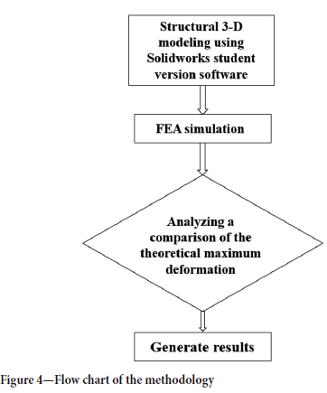
This study's primary aim is to determine the peak deflection experienced by the structural frame of the EPRSDC chassis when subjected to static loading conditions. A comprehensive flow chart (Figure 4) is employed to provide a clear visualization of the entire research methodology.
The experimental set-up encompassed the simulation of the crawler's operational conditions both under water and at its stationary position. This simulation accounted for factors such as the hydrostatic pressure exerted by the surrounding water, considering the upward-facing component of the crawler. The EPRSDC hardware design was systematically partitioned into three fundamental components prior to the final integration, which was accomplished using the Tetrix Max robotics kit. Specifically, the undercarriage system was subdivided into three distinct elements: the venturi dredging arm, the driving base, and the internal frame. The resulting design dimensions measured 450 mm x 412 mm.
Modelling
Utilizing SolidWorks 2019 software, a comprehensive three-dimensional modelling process was conducted, as illustrated in Figure 4. The software was instrumental in performing a static loading analysis of the EPRSDC's chassis, constructed from 1050 aircraft-grade aluminium.
In accordance with Romahadi, Fitri, and Buana (2023), it is emphasized that weight significantly influences the performance of any moving vehicle, whether subsea or on the ground. Addressing this concern, the authors aimed to develop a lightweight cast wheel design model capable of withstanding a load of 535 N. This necessitated a meticulous analysis involving comparative assessments of various design models and material variations, complemented by static simulations executed using SolidWorks 2018 software. The anticipated outcomes encompassed critical parameters such as von Mises stress, displacement, strain, and factor of safety, with a distinct emphasis on achieving a lightweight design.
The simulation results across the three models affirm their capacity to safely endure a load of 535 N, as validated by factor of safety values consistently exceeding the threshold of unity. Moreover, the adapted wheel designs, incorporating diverse materials, demonstrate a reduction in mass compared to the original wheel configurations. Following rigorous material testing, these designs are determined to be structurally sound, as the calculated safety factors meet the prescribed minimum requirements for static loading conditions (i.e., not less than unity).
Notably, the magnesium alloy ZK60A exhibits the highest safety factor owing to its superior yield strength of 303 MPa, surpassing the yield strength of aluminium alloy 6061-T6 at 276 MPa. These findings underscore the distinct advantage of the redesigned wheel configuration, yielding a lighter mass in contrast to the original wheel design.
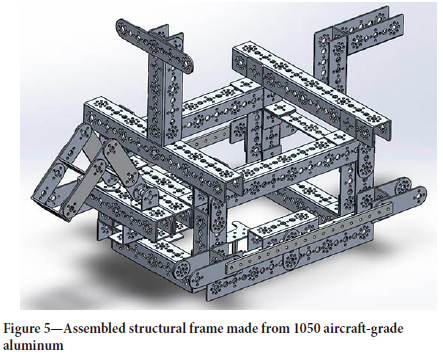
The frame, as shown in Figure 5, served as the basis for a FEA simulation to ascertain the viability of employing 1050 aircraft-grade aluminum in the construction of prospective EPRSDCs. Precise measurements of the weight of selected components were taken, with these values subsequently employed to apply specific loads to discern potential areas of deformation.
Finite element analysis
FEA was employed to assess the structural integrity, a critical factor in ensuring the robustness of the EPRSDC framework. A meticulous examination of the EPRSDC chassis was deemed imperative in meeting established standards. The choice of SolidWorks FEA as the analytical tool was driven by its demonstrated efficacy in such evaluations.
Material selection
Table I presents the material properties of 1050 aircraft-grade aluminum, sourced from SolidWorks (2019).
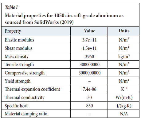
The selection of 1050 series aluminum is grounded in its adherence to the anticipated characteristic attributes of diversified application. Moreover, it demonstrates a diminished potential for environmental impact, particularly in terms of ocean pollution, in the context of marine operations.
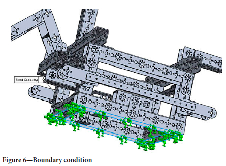
Boundary fixed condition
The chosen boundary conditions (Figure 6) involved eight specific areas with fixed points. These points were situated at the under-channels, featuring two points of support at each chanel.
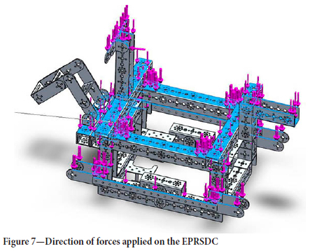
Loaded force
Figure 7 illustrates the downward force exerted on the structural frame model. This load was uniformly distributed across the component. The weight of each component, detailed in Table II, was calculated, initially in kilograms, then converted to grams, and ultimately to newtons.
Static loaded force
Meshing of the structural frame
In the certification process for the preliminary design of the vehicle structure, it is imperative to take into account the rigorous and unpredictable real-world conditions it will face. This simulation is focused on identifying potential failures that may jeopardize the robot's structural integrity. The mesh model, as depicted in Figure 8, provides a comprehensive overview of the primary shell mesh. It highlights the reference nodes, which are significant in relation to the chassis surfaces subjected to compressional forces. This representation also underscores the mesh spacing within the shell model and exhibits structural variations.
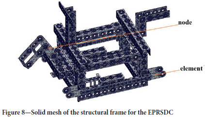
The nodes serve as pivotal points for coordinating spatial location where degrees of freedom (DOFs) are precisely defined within the aluminium material. Meanwhile, the elements within the material remain unified.
Results
The calculated forces were applied to different components of the crawlers frame as seen in Figure 7.
Von Mises stress distribution
Figure 9 presents a crucial facet of the analysis, showcasing the von Mises stress distribution (comprising both active and residual stress)
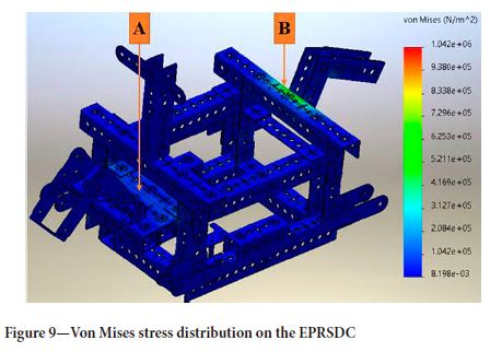
across the entire chassis of the crawler. Notably, the areas exhibiting the highest stress concentration, denoted as A (pressure pump base) and B (boom arm base), manifest stress values in the range of approximately 4.2 x 10⁵ N/m2 and 7.2 x 10⁵ N/m2, respectively. These points are highlighted in green on the von Mises stress data table. It is noteworthy that this stress region remains below the yield stress threshold of 1050 aircraft-grade aluminium. Consequently, the material demonstrates commendable performance under the applied loading conditions, characterized by a low risk of failure. This analysis further underscores that the majority of components fall within the safe range, exhibiting stress values ranging from 8.1 x 10³ N/m2 to 2.08 x 10⁵ N/m2.
In evaluating the structural model in terms of FOS, it is observed that the FOS exceeds 3, aligning with acceptable standards. It is imperative to maintain the working stress on the material at least three times lower than its yield stress. The fact that the point of maximum stress concentration remains comfortably below the yield stress affirms that the model will not fail under the combined weight of its components.
Displacement
As depicted in Figure 10, the points exhibiting the maximum displacement are on the boom arm (A) and pump mount base (B). This displacement is attributed to the moment of force acting on the component, which surpasses the longer perpendicular distance between the base point and the endpoints of the arm and pump mount. An increase in the distance between points A and B will result in an increase in the maximum displacement of the structural frame. We therefore propose locating the pump mount arm on the beam, with the arm being reinforced by channels from beneath the base. The point of maximum displacement registers within the red zone, measuring 4.5 x 10⁻⁶ m (0.0000455 mm). This result is deemed acceptable, as the displacement magnitude is exceedingly minute and exerts negligible influence on the crawler's performance.
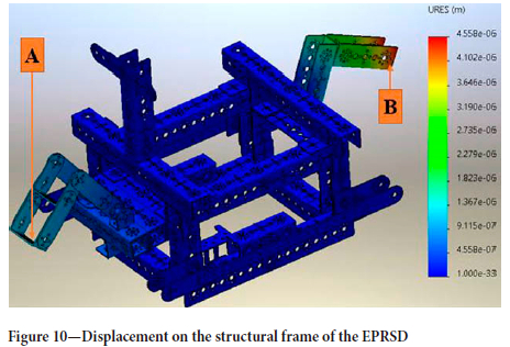
In conclusion, there exists potential for refining or optimizing the design to enhance performance. The range of displacement within the blue zone spans from 4.55 x 10⁻⁷ m to 1.0 x 10⁻³³ m, affirming the vehicle's capability to withstand its own weight under anticipated operational conditions. To further fortify the design, considerations such as reinforcements or the implementation of a denser material can be explored.
Strain
Figure 11 delineates the strain distribution across the EPRSDC model, portraying the material's physical deformation in response to the applied force. Strain is defined as the ratio of the change in length to the original length of a solid material model.
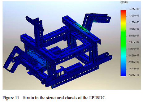
For this analysis, we considered the Cauchy strain metric and evaluated the strain limits specific to various materials. Exceeding these limits may lead to structural failure by cracking or breakage. Our model manifests a maximum strain of 8.8 x 10⁻⁷, which falls below the established strain limit of the material. Notably, most of the material strain is concentrated within the blue region, measuring 1.4 x 10⁻⁷. This indicates that the components integrated into the model are operating well within their designated safe strain limits.
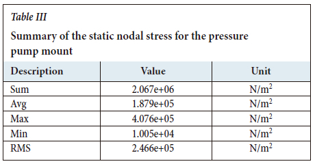
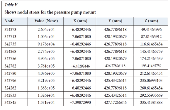
Plotted points of the affected part of the pressure pump mount
The stress plots (N/m2) at 11 characteristics points in the X, Y, and Z directions (mm) are given in Table IV
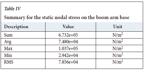
Plotted points of the affected part of the boom arm base
The stress plots (N/m2) at 11 characteristics points in the X, Y, and Z directions (mm) are shown in Table V
Discussion
FEA graph for 1050 aircraft-grade aluminium static loading simulation for pressure pump base mount
Figure 14 illustrates the von Mises stress distribution at selected nodes. This graph offers insight into the stress profile along the 288 mm channel during the simulated process under static loading conditions for the structural frame chassis. Following the application of a load of 0.73 N to the 39068_txm-288 mm channel (3)-1, the von Mises stress underwent fluctuations at node #342713.
It initially increased to 2.6 x 10⁴ N/m2, subsequently dropping to its lowest point at 1.0 x 10⁴ N/m2 at node #324273. The stress then exhibited a progressive surge, reaching 9.1 x 10⁴N/m2, which further escalated to 2.77 x 10⁵ N/m2. A subsequent peak stress of 3.9 x 10⁵ N/m2 was reached, followed by a slight decrease to 3.7 x 10⁵ N/m2 at node #342782. The stress subsequently peaked at its highest value of 4.0 x 10⁵ N/m2 at node #342780. From there, it began to gradually decline, reaching its ultimate minimum at 1.5 x 10⁵ N/m2. The graph also underscores two critical points of maximum stress located at the middle of the 288 mm channel, denoted as the maximum stress points of 3.9 x 10⁵ N/m2 and 4.0 x 10⁵ N/m2, corresponding to the base mount on which the pump is affixed.
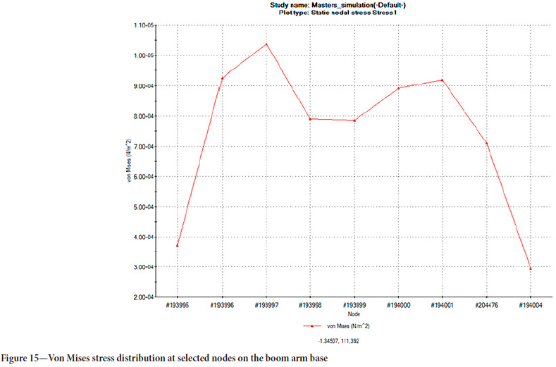
FEA graph for 1050 aircraft-grade aluminium static loading simulation for the boom arm base
Figure 15 presents an analysis of nine selected points on the boom arm base, which bears the weight of the entire arm. The combined weight of the base and arm was quantified as 2.808 N. Von Mises stress distribution was then plotted across the cross-sectional area of the 160 mm channel beam. The analysis revealed notable stress points, initiating at a minimum of 3.7 x 10⁴ N/m2 at node #193995. The stress levels underwent a rapid escalation, culminating in a maximum stress of 1.0 x 10⁴ N/m2. There was a slight reduction in stress on the beam from 7.9 x 10⁴ N/m2 to 7.8 x 10⁴ N/m2.
Furthermore, a surge in stress was observed, from 8.9 x 10⁴ N/m2 to 9.2 x 10⁴ N/m2, leading to the second recorded maximum stress. This value subsequently decreased to 7.1 x 10⁴ N/m2 and ultimately to 2.9 x 10⁴ N/m2. In conclusion, it is evident that the material experiences two distinct maximum stress points, measuring 1.0 x 10⁴ N/m2 and 9.2 x 10⁴ N/m2. Notably, the results indicate minimal deformation during the course of the experiment.
Conclusion
The static loading simulation, executed through finite element analysis (FEA), yielded critical insights into the maximum deformation and von-Mises stresses exerted on the structural frame of the crawler. This assessment pinpointed specific areas of vulnerability, notably the boom arm and dredging pump base, where stress concentrations were most prominent. Iit is strongly recommended that these weak points are reinforced in forthcoming iterations of the crawler.
Furthermore, the simulation generated two distinct graphs, one for the pump mount base and another for the boom arm base mount. The 1050 aircraft-grade aluminium demonstrated commendable performance, underscoring its suitability for future developments and providing valuable insights for refined material selection in subsequent iterations. This substantiates its viability for continued use in the advancement of crawler designs.
Acknowledgment
I wish to acknowledge Cape Peninsula University of Technology, Technology Innovation Agency (TIA) South Africa and the Ad Aptronics Advanced Manufacturing Technology Laboratory (AMTL) for their support and contribution towards the success of this research. Special thanks to Associate Professos Atanda K. Raji and Associate Professor Oscar Philander for their support.
References
Chutia, S., Kakoty, N.M., and Deka, D. 2017. A review of underwater robotics, navigation, sensing techniques and applications. ACM International Conference Proceeding Series, Part F132085. pp. 1-6. https://www.researchgate.net/publication/321237107_A_Review_of_Underwater_Robotic _Navigation_Sensing_Techniques_and_Applications [accessed 30 July 2021] [ Links ]
Dai, Y., Yin, W., and Ma, F. 2019. Nonlinear multi-body dynamic modeling and coordinated motion control simulation of deep-sea mining system. IEEE Access, vol. 7. pp. 86242-86251. https://www.researchgate.net/publication/334102401_Nonlinear_Multi-Body_Dynamic_Modeling_and_Coordinated_Motion_Control_Simulation_of_Deep-Sea_Mining_System [ Links ]
IMDH Group. 2016. Team | IMDH Group International Mining & Dredging Holding Ltd. : 1-3. https://www.imdhgroup.com/team.php [accessed 28 July 2021] [ Links ]
Lian, W. and Yao, W. 2010. Fatigue life prediction of composite laminates by FEA simulation method. International Journal of Fatigue, vol. 32, no. 1. pp. 123-133. http://dx.doi.org/10.1016/j.ijfatigue.2009.01.015 [ Links ]
Lloyd-Smith, M. and Immig, J. 2018. Ocean pollutants guide. Toxic threats to human health and marine life. National Toxics Network (NTN). 108 pp. https://ipen.org/sites/default/files/documents/ipen-ocean-pollutants-v2_1-en-web.pdf [accessed 31 July 2021] [ Links ]
Medagedara, N.T. and Chandra, P.D.S. 2012. Comparing the theoretical and Finite Element stress-strain analysis for axial and torsion loading. https://www.researchgate.net/publication/313504104_Comparing_the_theoretical_and_Finite_Element_stress-strain_analysis_for_axial_and_torsion_loading [ Links ]
Romahadi, D., Fitri, M., and Buana, U.M. 2023. Implementation of the finite element method in Solidworks to optimize the front cast wheel design for motorcycles. International Journal of Innovation in Mechanical Engineering & Advanced Materials (IJIMEAM), vol. 4, no. 3. pp. 66-73. https://publikasi.mercubuana.ac.id/index.php/ijimeam/article/download/18794/pdf [ Links ]
Thavai, R., Shahezad, Q., Shahrukh, M., Arman, M., and Imran, K. 2015. Static analysis of go-kart chassis by analytical and Solid Works simulation. International Journal of Modern Engineering Research, vol. 5, no. 3. pp. 661-663. [ Links ]
Yang, C., Huang, K., Li, Y., Wang, J., and Zhou, M. 2012. Review for development of hydraulic excavator attachment. Energy Science and Technology, vol. 3, no. 2. pp. 93-97. https://core.ac.uk/download/pdf/236300336.pdf [ Links ]
Yoon, S.M., Hong, S., Park, S.J., Choi, J.S., Kim, H.W., and Yeu, T.K. 2012. Track velocity control of crawler type underwater mining robot through shallow-water test. Journal of Mechanical Science and Technology, vol. 26, no. 10. pp. 3291-3298. [ Links ]
 Correspondence:
M.O. Ojumu
Email: mikeoluwaseunojumu@gmail.com
Received: 8 Sept. 2022
Revised: 20 Sept. 2023
Accepted: 25 Sept. 2023
Published: October 2023
* Paper written on project work carried out in partial fulfilment of the Degree Master of Engineering (Mechanical Engineering).

