


Serviços Personalizados
Artigo
 Inglês (pdf)
 Artigo em XML
 Referências do artigo
Indicadores

Links relacionados
-
 Citado por Google
 -
 Similares em Google
Compartilhar

 Permalink
Journal of the Southern African Institute of Mining and Metallurgy
versão On-line ISSN 2411-9717
versão impressa ISSN 2225-6253
J. S. Afr. Inst. Min. Metall. vol.123 no.8 Johannesburg Ago. 2023
http://dx.doi.org/10.17159/2411-9717/1707/2023
PROFESSIONAL TECHNICAL AND SCIENTIFIC PAPERS
Mechanism and control of deformation in gob-side entry with thick and hard roof strata
J.S. GuoI; L.Q. MaII; I. NgoII
ISchool of Civil Engineering, Xuzhou University of Technology, Xuzhou, Jiangsu Province, China
IIState Key Laboratory of Coal Resources and Safe Mining, School of Mines, China University of Mining and Technology Xuzhou, China
SYNOPSIS
Deformation of gob-side entries has always been a critical concern for ensuring stability in longwall coal mines. This paper addresses the significant deformation and support challenges that arise in thick and hard roof longwall faces (THRLF) due to dynamic pressure. The study aims to elucidate the characteristics and mechanisms of deformation during the retreat of the longwall face. The research findings indicated that the primary cause of deformation was the combination of advanced abutment stress resulting from longwall face mining and the movement of the lateral roof over the chain pillar. To mitigate this issue, we propose a deformation control method known as cutting off the lateral roof (COLR) over the chain pillar. Simulation results demonstrate a significant reduction in roof stress and deformation of the gob-side entry after implementing the lateral roof-cutting technique. These findings provide valuable guidance for effectively managing deformation in gob-side entries, particularly when dealing with thick and hard roof strata.
Keywords: thick and hard roof longwall face (THRLF), gob-side entry deformation, roof structure; control method, cutting off the lateral roof (COLR).
Introduction
Thick and hard roof strata are strata that are characterized by great thickness, high strength, and the absence of joints or fractures. These strata accumulate a significant amount of elastic deformation energy during the post-mining of the coal seam (Coggan et al., 2012). When fractures occur in the thick and hard roof, the accumulated energy is suddenly released, resulting in substantial deformation (Guo et al., 2017). Traditionally, gob-side entries are situated within a range of 0-50 m (the width of the chain pillar) from the last mined-out panel, which is determined by the layout of the longwall face (Li et al., 2015). As a result, the gob-side entry experiences both the primary mining impact (PMI) from the last face and the secondary mining impact (SMI) induced by the active mining face (Li et al., 2017; Hua et al., 2018). This is particularly significant for entries located in thick and hard roof longwall faces (THRLF), as the stress and deformation effects are more pronounced, increasing the likelihood of dynamic failure (Islam and Shinjo, 2009; Elmo and Stead, 2010).
Iannacchione and Tadolini, 2016) have shown that the hard roof plays a significant role in inducing deformation at the gob-side entry. (Lawson et al., 2016) have further emphasized that the thickness of the roof and its distance from the coal seam are important factors contributing to the development of deformation. Building upon this, (Lou et al., 2016) highlighted that the deformation in the entry is caused by a combination of the advanced abutment stress from the longwall face and the fractures occurring in the thick and hard roof.
To control deformation in the gob-side entry, two main approaches are commonly used: passive support and active prevention (Liu et al., 2012). Passive support focuses on reducing deformation through the strengthening of support systems. (He et al., 2011) proposed a support scheme using intensive cable trusses and small-diameter anchors with high pre-stressed tension. Wang et al., (2014) suggested the use of high-strength bolts with high pre-stress tension as a support scheme. However, the passive support method was found to be ineffective and disrupted regular production of the longwall face (Wang et al., 2015). On the other hand, active prevention aims to address the main cause of deformation by adjusting the width of the coal pillar to maintain entry stability. Bai et al. (2015) and Feng et al. (2018) proposed locating the entry in a stress reduction zone, achieved by reducing the coal pillar width (the lateral stress of the surrounding rock can be divided into three zones: the stress reduction zone, stress increase zone, and original rock stress zone). However, designing a small chain pillar requires careful consideration of multiple factors to prevent more serious deformations. Xu et al. (2017) prevented deformation by increasing the width of the chain pillar to isolate the mining effects of two adjacent faces. However, wider coal pillars result in coal resource wastage. In recent years, the 'cutting off roof strata method' has been adopted in various mines to maintain entry stability with the development of related technologies (He et al., 2017). This method involves arranging a cutting line at the edge of the gob along the strike of the entry. By blasting or hydraulic fracturing, the hanging part of the lateral roof strata is removed, eliminating its impact on the entry.
This paper analyses the deformation events of 11215 tail entry in the Xiaojihan coal mine. The mechanism of deformation of the gob-side entry in THRLF was investigated. Finally, the deformation control method was proposed to eliminate or weaken the deformation of the gob-side entry.
Geological conditions of the study area
Mining geological conditions
The coal seams in Northern Shaanxi are part of the Jurassic coalfields, which contribute approximately 7% of Chinas total annual coal output. These coalfields can be further divided into Yushen and Yuheng fields. The Yushen field is characterized by shallow coal seams that range from 40-200 m in depth. Due to this relatively shallow depth, the coal seam in this area has been extensively exploited on a large scale. On the other hand, the Yuheng field consists of deeper coal seams, with depths ranging from 300-500 m.
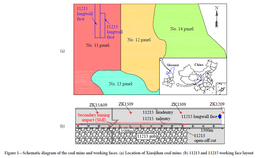
The Xiaojihan mine, located in the Yuheng field, is the first modern mine in the area and has a production capacity of 10 Mt/a. Due to its significance, the mining experience gained from Xiaojihan is of great importance for the design and operation of subsequent mines in the region. Within Xiaojihan mine, the 11215 longwall face is situated in Panel 11. It is adjacent to the 11213 gob, as shown in Figure 1. The chain pillar between these two faces has a width of 20 m. The 11215 face extends 4,888 m in the direction of mining and has a width of 280 m. The 11215 headentry and tail entry serves the 11215 longwall face. It should be noted that the 11215 tailentry, which is the gob-side entry, experiences disturbance due to the mining activities on both the 11213 faces (PMI) and the 11215 faces (SMI). In Figure 1, the region of SMI is highlighted by the red ellipse, with a length of 3588 m. This paper primarily focuses on analysing and understanding the deformation events that occur in the region of SMI within the 11215 tailentry.
Roof geological conditions
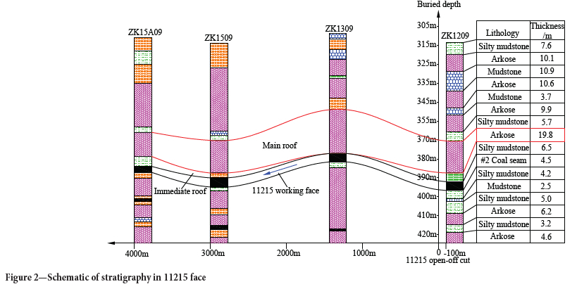
Taking the 11215 longwall face as an example, four geological boreholes were arranged along the advancing direction of the face (Figure 2).
he distances from the 11215 open-off cut were 00 m, 1455 m, 3000 m, and 4000 m, respectively. The roof strata of the 11215 face exhibit an alternating layered structure composed of arkose and mudstone. Notably, arkose layers with a thickness exceeding 5 m constitute 58.2% of the total thickness, indicating a predominant presence of intact arkose in the roof strata.
Characteristics of deformation in gob-side entry
Deformation of the 11215 tailentry
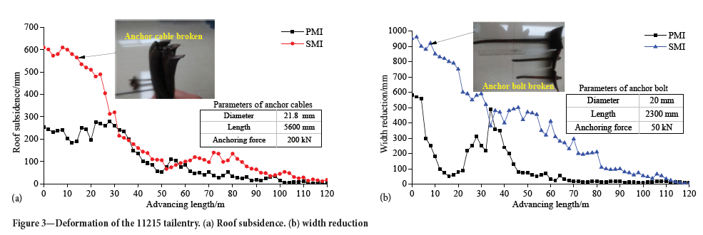
Before the 11215 face advanced to the 11213 gob (PMI), the deformation of the 11215 tail entry occurred mainly within the range of 0-40 m preceding the 11215 face. The maximum recorded roof subsidence was 295 mm, accompanied by a width reduction of 585 mm. After the 11215 working faces advanced to the 11213 gob (SMI), the deformation was characterized by severe convergence m of the whole section. The deformation was mainly within the range of 0-60 m preceding the 11215 face. Maximum roof subsidence and width reduction were 610 mm and 956 mm, respectively. An anchor cable in the roof and an anchor bolt in the chain pillar were broken within the range of 0-20 m preceding the 11215 face (Figure 3).
Deformation events
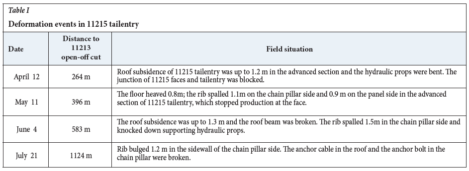
During the advance of the 11215 face towards the 11213 gob, a series of significant failure events were observed. To analyse these events, four typical incidents were selected and are documented in Table I and illustrated in Figure 4.
Mechanism of deformation in gob-side entry
Advanced abutment stress caused by longwall face mining
FLAC3D software was used to simulate and analyse the stress and deformation patterns during the mining operations of longwall working faces. FLAC3D is a renowned finite difference numerical simulation software package that incorporates diverse material models to accurately replicate the stress and deformation behaviors of elastic-plastic media, including rock and soil. It enjoys widespread adoption and recognition within the domains of rock mechanics, soil mechanics, and mining engineering.
Parameters of the model
Geometric dimensions
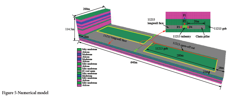
A model with dimensions of 640 x 200 x 114.5 m was constructed to simulate the strata movement (Figure 5). Strata 114.5 m thick were modelled and the rest of the overburden stress was exerted on the top boundary as pressure (Jaiswal and Shrivastva, 2009; Sherizadeh and Kulatilake, 2016).
Boundary conditions
Displacement constraints were applied to the front, back, left, right, and bottom boundaries. To eliminate the disturbance effect caused by coal seam mining, the boundary of the model should exceed the boundary of the basin formed when the surface above the goaf subsides. In this modelling scenario, the rock strata movement angle was assumed to be 75° (Qian et al., 2003; Xu et al., 2017).
After calculations, it was determined that leaving 22.7 m coal pillars on both sides would ensure sufficient mining. Therefore, a boundary of 26 m and 28 m was left on both sides of the inclined direction, while a boundary of 25 m was left on both sides of the strike direction, satisfying the requirements.
Rock/coal strata properties
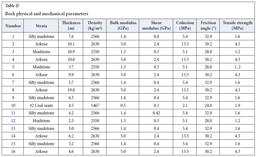
The Mohr-Coulomb failure criterion was used in the model. The detailed physical and mechanical parameters for each rock layer and coal seam in the model can be found in Table II, providing comprehensive information for the analysis and modeling process.
Monitoring points layout
To monitor the stress and deformation of 11215 tail entry, four monitoring points were created. P1 is monitoring the variation of stress, P2 is monitoring the variation of roof subsidence, and P3 /P4 are monitoring the variation of width reduction.
Excavation steps
The excavation process of the model follows the actual mining sequence. It begins by mining the mining roadway, followed by excavation of the 11213 working face, and finally the 11215 working face. The progression of the mining process aligns with the real-time mining progress, which was typically at a rate of 10 m/d. The excavation was carried out every 10 m in accordance with this mining schedule. This approach ensures that the model accurately represents the sequential excavation process observed in practical mining operations.
Simulation results
To analyse the excavation process in detail, five stages were selected for analysis:
Stage 1: Extraction of the 11215 tailentry.
Stage 2: Mining of the 11213 face (PMI).
Stage 3: Advancement ofthe 11215 face to the location of the 11213 open-off cuts (SMI).
Stage 4: Advancement ofthe 11215 face to a location approximately 20 m away from the 11213 open-off cut (SMI).
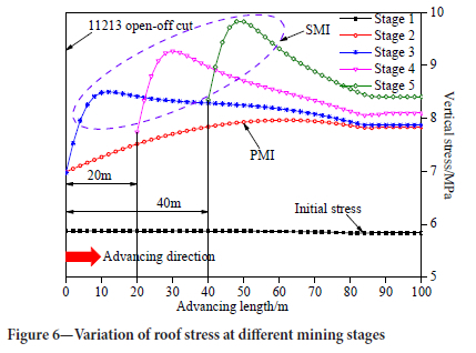
Stage 5: Advancement ofthe 11215 face to a location approximately 40 m away from the 11213 open-off cut (SMI). These stages were chosen to closely examine the specific steps and events during the model excavation process. In this section 'measured' means 'as calculated by the model.
These stages were chosen to closely examine the specific steps and events during the model excavation process. In this section 'measured' means 'as calculated by the model.
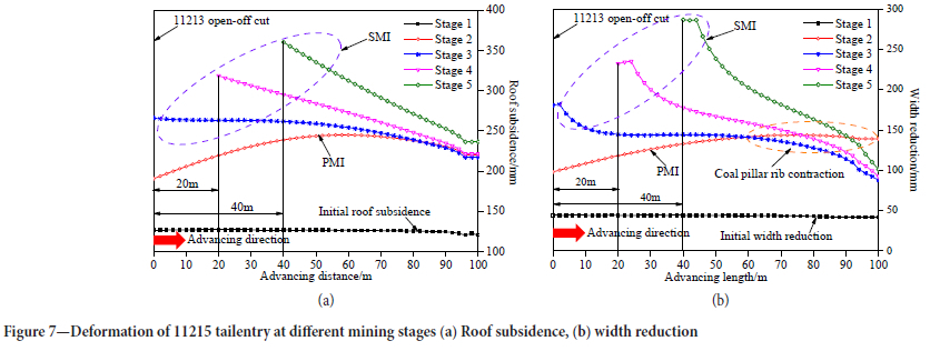
After the excavation of the 11215 tail entry (Stage 1), the vertical stress measured was 5.9 MPa. This stress increased to 8.0 MPa after the mining of the 11213 faces (Stage 2, PMI). As the 11215 faces advanced to the location of the 11213 open-off cuts (Stage 3, SMI), the peak abutment stress in the advanced section of the 11215 tail entry reached 8.5 MPa. Further advancement of the 11215 face to a location approximately 20 m away from the 11213 open-off cuts (Stage 4, SMI) resulted in a peak abutment stress of 9.3 MPa in the advanced section of the 11215 tail entry. Finally, when the 11215 face advanced to a location approximately 40 m away from the 11213 open-off cuts (Stage 5, SMI), the peak abutment stress in the advanced section of the 11215 tail entry reached 9.8 MPa (as depicted in Figure 6 and summarized in Table III).
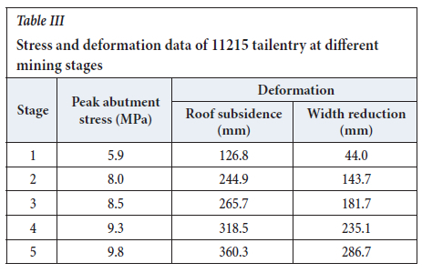
After the excavation of the 11215 tail entry (Stage 1), the roof subsidence in the advanced section was measured at 126.8 mm, and the width reduction of the two sidewalls was 44.0 mm. Upon mining the 11213 working face (Stage 2, PMI), the roof subsidence of the 11215 tail entry increased to 244.9 mm, and the width reduction of the two sidewalls increased to 143.7 mm. When the 11215 face advanced to the location of the 11213 open-off cut (Stage 3, SMI), the maximum subsidence of the roof and the width reduction of the two sidewalls in the advanced section reached 265.7 mm and 181.7 mm, respectively. Further advancement of the 11215 face to a location approximately 20m away from the 11213 open-off cut (Stage 4, SMI) resulted in a maximum roof subsidence of 318.5 mm and a width reduction of the two sidewalls of 235.1 mm. Finally, as the 11215 face advanced to a location approximately 40 m away from the 11213 open-off cut (Stage 5, SMI), the maximum roof subsidence in the advanced section of the 11215 tail entry reached 360.3 mm, with a width reduction of the two sidewalls of 286.7 mm (as depicted in Figure 7 and summarized in Table III).
Ultimately, it is important to note that the roof stress and deformation experienced by the simulated 11215 tail entry during the SMI phase were markedly greater compared to the PMI phase
As a result, it becomes evident that the intensified abutment stress resulting from the mining of the 11215 longwall face stands as a significant contributing factor to the deformation observed in the gob-side entry. This highlights the profound impact of longwall face mining on the stability and structural integrity of underground mining systems.
Movement of the lateral roof over chain pillar
Relationship between lateral roof and entry's stability
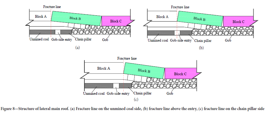
Roof strata were subjected to bending subsidence along the inclined direction of the longwall face, resulting in Blocks A, B, and C that were hinged to each other. Investigations indicated that the deformations of gob-side entry under three different spatial positions of the main roof fracture line were different (Zha et al., 2014; Yin et al., 2016; Xu et al., 2017). The position of the main roof fracture line can be categorized as follows:
➤ The fracture line was located on the side of the unmined coal (Figure 8a)
➤ The fracture line was directly above the gob-side entry (Figure 8b)
➤ The fracture line was located above the chain pillar (Figure 8c).
Numerical simulations and on-site data have provided evidence that when the fracture line was situated on the side of the unmined solid coal, it resulted in the greatest length of the suspended roof. This, in turn, leads to the highest bending moment, as well as the most severe stress and deformation in the rock surrounding the entry. On the contrary, when the fracture line is positioned above the coal pillar, it results in the shortest length of the suspended roof, the lowest bending moment, and the most stable surrounding rock in the entry.
Mechanical model of lateral roof
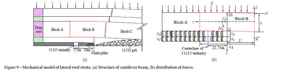
As mentioned above, the stability of 11215 tail entry was mainly dependent on the structure of the lateral main roof over the chain pillar. Therefore, the structure of the cantilever beam was established (Figure 9).
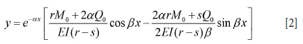
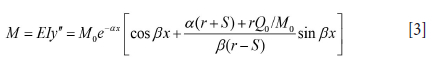
The main roof stratum can be considered as a semi-infinite beam, subjected to vertical force P and axial force N, as described in previous studies (Qian et al., 2003; Pan and Gu, 2015). Based on the principles of Timoshenko beam theory, the deflection curve equation for the main roof can be expressed as follows:

where P + -ky.
where: E is the elastic modulus of roof strata; y is the vertical displacement of the main roof; k is Winkler bed coefficient.
According to boundary conditions, the deflection curve equation can be obtained as follows [Qian et al., 2003]:
Herein:
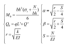
where: h is the main roof thickness (19.8 m); E is the elastic modulus of the main roof (7.36 GPa); I is the section moment of the main roof (I=bh3/12, where b=1); ∆s is the vertical displacement of Block B (∆s=h/6); Lb is the length of Block B; L' is the length of the hanging part of Block B (11.7 m in this case, more details in the next section); Q is the shear force between fractured rock blocks (Q'=Lb(yh+q)); y is the bulk density of main roof (23 kN/m3 in this case); q is the loads on strata above the main roof (9.25x10³ kN/m in this case); N is the axial force (N=LB Q72(h-As)); k is the bed coefficient of coal and immediate roof 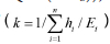 , immediate roof thickness coal seam thickness h1 = 4.5 m, E1 = 1.06 GPa, h2=6.5 m, E2=1.67 GPa, k = 1.23x10³ kN/ m.
Hanging length of Block B
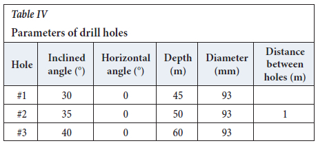
To determine the actual length of the hanging part of Block B, a hydraulic drilling technique was employed. By monitoring the leakage of flushing fluids in the drill-holes, the development of fracture zones in the overburden strata could be determined. The drill site was situated at a distance of 520 m from the 11213 open-off cut. The drill holes were arranged in a fan pattern. The layout and parameters of the drill-holes can be seen in Figure 10 and Table IV.
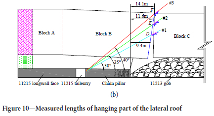
The detection results suggested that starting points of complete leakage of flushing fluids in 30°, 35° and 40° drill holes were D, E, and F, respectively. The horizontal distances from D, E, and F to the boundary of the chain pillar, namely the length of the roof hanging part (L'), were 9.4 m, 11.6 m, and 14.1 m respectively. The average value was 11.7 m.
Fracture line location of the main roof
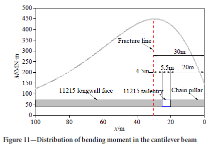
The bending moment at the cross section of the cantilever beam can be calculated by (Wang et al., 2014; Xu et al., 2017):
Substituting the parameters of 11215 face into Equation (3), the bending moment of the cantilever beam could be obtained (Figure 11). The maximum value of the bending moment was calculated at x = 30 m and the fracture line of the main roof was located at 30 m outside the chain pillar.
In conclusion, the core reason for deformation in 11215 tailentry was the superimposition effect of the advanced abutment stress caused by 11215 face mining and the bending of the lateral roof over the chain pillar.
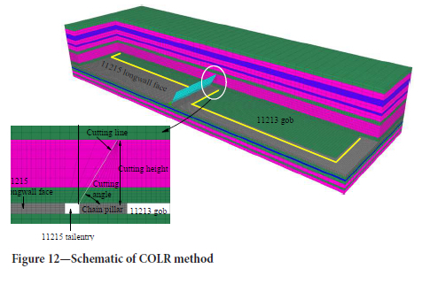
Control method of deformation in gob-side entry
Due to the inevitable advancement abutment stress generated by mining activities, the feasible approach is to regulate the lateral movement of the main roof. As a result, the 'cutting off the lateral roof' (COLR) method was implemented to manage the fracture line in the roof situated at the chain pillar side, as illustrated in Figure 12. The effectiveness of COLR primarily hinges upon optimizing the cutting height and cutting angle parameters. To achieve this, numerical simulations were conducted to refine and optimize these parameters, ensuring enhanced outcomes for the COLR technique.
Simulation scheme
This section of the simulation builds upon the numerical model discussed in Section 4. To simulate the cutting line, separate unit groups are set in the model, as illustrated in Figure 12. The primary focus of this study is to examine the impact of two factors: the height of the cutting seam (0 m, 5 m, 15 m, 25 m) and the angle (0°, 15°, 30°, 45°) on the stress and deformation of the surrounding rock in the 11215 tailentry.
Cutting height
The determination of the cutting height primarily depends on practical geological conditions, as indicated in previous studies (Poulsen, 2010; Jawed and Sinha, 2018). In the case of the 11215 tailentry, the immediate roof had a thickness of 6.5 m, while the main roof had a thickness of 19.8 m. Therefore, simulations were conducted to assess the variations in roof stress and deformation in the 11215 tailentry for different cutting heights: 5 m (approximately equal to the thickness of the immediate roof), 15 m, and 25 m (approximately equal to the combined thickness of the immediate roof and main roof).
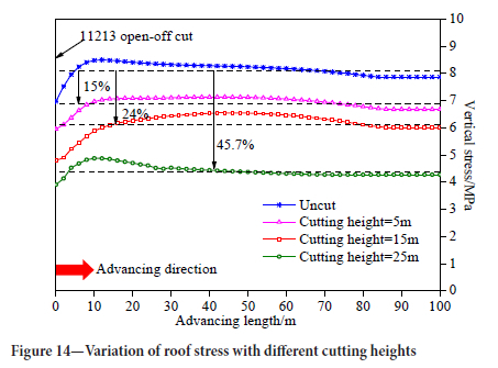
Variation of the roof stress
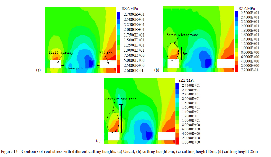
As the cutting height increased, the stress release zone above the 11215 tailentry expanded accordingly. This can be observed in Figure 13, where the scope of the stress release zone becomes larger with the increase in cutting height.
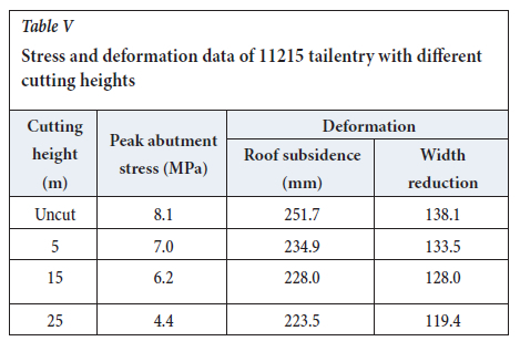
Analysis of the roof stress in the 11215 tail entry revealed the following results: When the roof was uncut, the average roof stress was 8.1 MPa. With a cutting height of 5 m, the average roof stress decreased to 7.0 MPa, representing a reduction of 15%. When the cutting height was increased to 15 m, the average roof stress further decreased to 6.2 MPa, showing a reduction of 24%. With a cutting height of 25 m, the average roof stress dropped significantly to 4.4 MPa, indicating a reduction of 45.7%. These findings are visually represented in Figure 14 and summarized in Table V.
Variation of the deformation
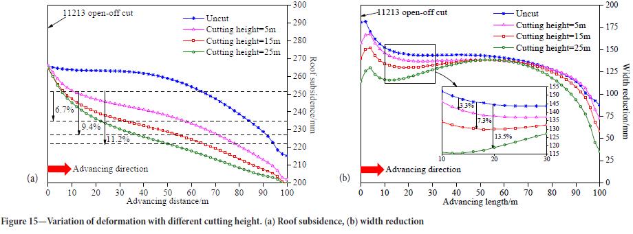
Figure 15 illustrates the variations in roof subsidence resulting from different cutting heights employed in the 11215 tail entry.
Without any cutting, the average roof subsidence in the 11215 tail entry was 251.7 mm. When the cutting height was set at 5 m, the average roof subsidence decreased to 234.9 mm, representing a reduction of 6.7%. With a cutting height of 15 m, the average roof subsidence further decreased to 228.0 mm, showing a reduction of 9.4%. By increasing the cutting height to 25 m, the average roof subsidence dropped to 223.5 mm, resulting in a reduction of 11.2%.
Additionally, the average width reduction also decreased as the cutting height increased. Specifically, the average width reduction decreased by 3.3%, 7.3%, and 13.5% when the cutting height increased from 5 m to 15 m and finally 25 m. These results are visualized in Figure 15a (roof subsidence) and Figure 15b (width reduction) and summarized in Table V.
In conclusion, the results of COLR were best when the cutting height was 25 m, that is when the cutting height can ensure cut off of the main roof.
Cutting angle
For the convenience of construction, the cutting angle was usually taken as an integer multiple of 5°. Therefore, the variation of the roof stress and the deformation of 11215 tailentry were simulated for cutting angles if 0°, 15°, 30°, and 45°.
Variation of the roof stress
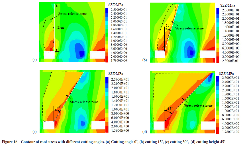
With the increase of cutting angle, the scope of the stress release zone in the surrounding rock above the 11215 tail entry increased (Figure 16).
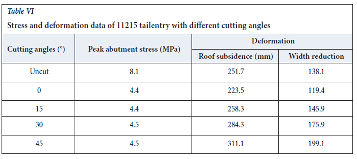
When the roof remained uncut in the 11215 tail entry, the average roof stress measured at 8.1 MPa. However, with different cutting angles, significant reductions in roof stress were observed. For a cutting angle of 0°, the average roof stress decreased to 4.4 MPa, representing a reduction of 45.7%. Similarly, at a cutting angle of 15°, the average roof stress reached 4.4 MPa, resulting in a decrease of 46.2%. When the cutting angle was set at 30°, the average roof stress measured 4.5 MPa, reflecting a decrease of 45%. Lastly, with a cutting angle of 45°, the average roof stress was recorded at 4.5 MPa, showing a decrease of 45.1%. (refer to Figure 17 and Table VI).
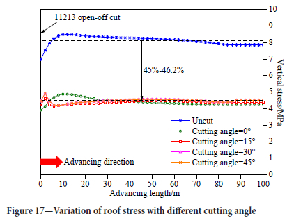
It is obvious that the cutting angle had only a minor effect on the roof stress. But the scope of the stress release zone became larger as the cutting angle increased.
Variation of the deformation
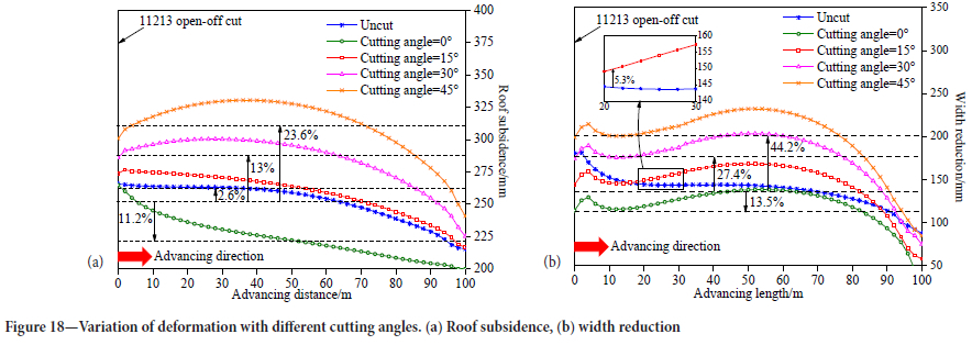
When the roof was left uncut, the 11215 tailentry exhibited an average subsidence of 251.7 mm. However, when the cutting angle was set to 0°, the average roof subsidence decreased to 223.5 mm, resulting in an 11.2% reduction. Interestingly, as the cutting angle increased beyond this range, namely to 15°, 30°, and 45°, the average roof subsidence showed consecutive increases of 2.6%, 13%, and 23.6% respectively (Figure 18a).
Similarly, when the cutting angle was set to 0°, the average roof subsidence of the 11215 tailentry decreased by 13.5%. However, as the cutting angle increased from 15° to 30° and 45°, the roof subsidence showed consecutive increases of 5.3%, 27.4%, and 44.2% respectively (refer to Figure 18b and Table VI). This can be attributed to the fact that as the cutting angle increased, the length of the hanging lateral roof above the 11215 tailentry also increased. Consequently, the deformation of the surrounding rock of the 11215 tailentry became more severe, leading to increased roof subsidence..
Based on the simulation results, it is observed that the deformation of the 11215 tailentry decreased when the cutting angle was set to 0° and slightly increased when the cutting angle was 15°. Considering both the roof release results and the deformation of the 11215 tailentry, it is recommended to maintain a cutting angle within the range of 0° to 15°.
Discussion
➤ The COLR method involves two primary techniques: borehole blasting and hydraulic fracturing (Huang et al., 2017). The borehole blasting technique generally yields superior stress release results, although it carries a relatively higher hazard level. Mishandling of this technique can lead to significant accidents (Liu et al., 2017). On the other hand, the hydraulic fracturing technique is considered safe and easily manageable. However, it may not be as effective as borehole blasting in achieving stress release for certain thick and hard rock formations.
➤The simulation results demonstrate that the COLR method yields optimal outcomes with a cutting angle of 0°. However, in practical situations, an excessively small cutting angle can lead to roof crushing and pose challenges for support. Hence, it is crucial to consider the geological strata and support conditions when determining the appropriate cutting angle.
➤ The advancing rate of the longwall face is also an important factor affecting the deformation of the gob-side entry. Statistical results show that deformation events in 11215 tail entry occurred when the advancing speed of 11215 face exceeded 10 m/d. For instance, 5 days prior to the '4.12' event, the average advancing speed of the working face was recorded as 11.5 m/d, peaking at 14.4 m/d. Similarly, 5 days leading up to the '5.11' event, the average advancing speed averaged at 10.1m/d, with a maximum speed of 12.7 m/d. Three days prior to the '6.4' event, the average advancing speed measured 12.0 m/d, with a peak speed of 13.35m/d. Finally, 4 days before the '7.21' event, the average advancing speed was documented at 12.0 m/d, reaching a maximum of 14.7 m/d. Therefore, it can be considered that reducing the advancing speed of the longwall face will reduce the possibility of deformation occurring in the gob-side entry.
Conclusions
➤ The roof stress and deformation of the gob-side entry were analysed through field observations and numerical simulations, revealing notable variations. The findings highlighted that the impact of secondary mining resulted in greater roof stress and deformation compared to that of primary mining.
➤ The mechanism behind deformation in the gob-side entry of a thick and hard roof longwall face was analysed. The primary factor was identified as the combined effect of advanced abutment stress resulting from longwall face mining and the lateral movement of the roof over the chain pillar. To further understand this phenomenon, mechanical structure models employing a cantilever beam approach were developed. Through calculations, it was determined that the fracture line of the roof was located approximately 30 m outside the chain pillar.
➤ A deformation control method for cutting off the lateral roof was proposed. The effectiveness of this method was evaluated by simulating stress release results under various cutting heights and cutting angles. The simulation revealed that the optimal outcome was achieved when the cutting height ensured the complete cut-off of the main roof, combined with a cutting angle ranging from 0° to 15°. This finding suggests that careful consideration of both cutting height and angle is essential for successful lateral roof deformation control.
Acknowledgements
This work was supported by The Natural Science Foundation of the Jiangsu Higher Education Institutions of China (23KJD440002) and Jiangsu Province Industry University Research Cooperation Project (BY20221261).
Author Contributions
Jinshuai Guo carried out the study and wrote the manuscript; Liqiang Ma supervised the study; Ichhuy Ngo proof read the manuscript.
Conflicts of Interest
The authors declare no conflict of interest.
References
Bai, J.B., Shen, W.L., Guo, G.L., Wang, X.Y., and Yu, Y. 2015. Roof deformation, failure characteristics, and preventive techniques of gob-side entry driving heading adjacent to the advancing working face. Rock Mechanics and Rock Engineering, vol. 48, no. 6. pp. 2447-2458. [ Links ]
Chen, S.Y., Song, C.S., Guo, Z.B., and Wang, Y. 2016. Asymmetric deformation mechanical mechanism and control countermeasure for deep roadway affected by mining. Journal of China Coal Society, vol. 41, no. 4. pp. 246-254. [ Links ]
Coggan, J., Gao, F.Q., Stead, D., and Elmo, D. 2012. Numerical modelling of the effects of weak immediate roof lithology on coal mine roadway stability. International Journal of Coal Geology. vol. 90, no. 1. pp. 100-109. [ Links ]
Elmo, D. and Stead, D. 2010. An integrated numerical modelling-discrete fracture network approach applied to the characterisation of rock mass strength of naturally fractured pillars. Rock Mechanics and Rock Engineering. vol. 43, no. 1. pp. 3-19. [ Links ]
Feng, G.R., Wang, P.F., Chugh, Y.P., Zhao, J.L., Wang, Z.Q., and Zhang, Z.P. 2018. A coal burst mitigation strategy for tailgate during deep mining of inclined longwall top coal caving panels at huafeng coal mine. Shock and Vibration. vol. 5929785. [ Links ]
Guo, J.S., Ma, L.Q., Wang, Y., and Wang, FT. 2017. Hanging wall pressure relief mechanism of horizontal section top-coal caving face and its application-a case study of the urumqi coalfield, China. Energies, vol. 10, no. 9. p. 1371. [ Links ]
He, F.L., Yin, D.P., Yan, H., Li, Q., and Yang, H.Z. 2011. Experiment of powerful anchor truss support system applied to mining roof falling gateway. Coal Science & Technology, vol. 39, no. 2. pp. 1-5. [ Links ]
He, M.C., Li, C., Gong, W.L., Sousa, L.R., and Li, S.L. 2017. Dynamic tests for a constant-resistance-large-deformation bolt using a modified SHTB system. Tunnelling and Underground Space Technology. vol. 64, no. 4. pp. 103-116. [ Links ]
Hua, X.Z., Ming, Y., Liu, Q.J., and Yang, P. 2018. Model test on evolution mechanism of floor heave in gob-side retaining entry of deep mine. Journal of Mining and Safety Engineering. vol. 35, no. 1. pp. 1-9. [ Links ]
Huang, B.X., Chen, S.L., and Zhao, X.L. 2017. Hydraulic fracturing stress transfer methods to control the strong strata behaviours in gob-side gateroads of longwall mines. Arabian Journal of Geosciences. vol. 10, no. 11. p. 236. [ Links ]
Iannacchione, A.T. and Tadolini, S.C. 2016. Occurrence, predication, and control of coal burst events in the US. International Journal of Mining Science and Technology. vol. 26, no. 11. pp. 39-46. [ Links ]
Islam, M.R. and Shinjo, R. 2009. Numerical simulation of stress distributions and displacements around an entry roadway with igneous intrusion and potential sources of seam gas emission of the Barapukuria coal mine, NW Bangladesh. International Journal of Coal Geology, vol. 78, no. 4. pp. 249-262. [ Links ]
Jaiswal, A. and Shrivastva, B.K. 2009. Numerical simulation of coal pillar strength. International Journal of Rock Mechanics and Mining Sciences, vol. 46, no. 4. pp. 779-788. [ Links ]
Jawed, M. and Sinha, R.K. 2018. Design of rhombus coal pillars and support for roadway stability and mechanizing loading of face coal using SDLs in a steeply inclined thin coal seam-a technical feasibility study. Arabian Journal of Geosciences, vol. 11, no. 15. p. 415. [ Links ]
Lawson, H.E., Tesarik, D., Larson, M.K., and Abraham, H. 2016. Effects of overburden characteristics on dynamic failure in underground coal mining. International Journal of Mining Science and Technology. vol. 27, no. 1. pp. 121-129. [ Links ]
Li, J.Z., Zhang, J.B., Hou, J.L., Wang, L., Yin, Z.Q., and Lim, CM. 2015. Multiple disturbance instability mechanism of dynamic pressure roadway and mining sequence optimization. Journal of Mining and Safety Engineering, vol. 32, no. 2. pp. 439-445. [ Links ]
Li, Y.F. and Hua, X.Z. 2012. The Stability of key block and calculating the width of roadside backfill in a secondary gob-side entry retaining. Journal of Mining and Safety Engineering, vol. 29, no. 6. pp. 783-789. [ Links ]
Li, Y.K., Hao, Z., Li, B., Huo, T.H., and Zhang, H. 2017. Plastic zone evolution law and enhanced support technology of surrounding rock in gateway retained along goaf with double gateway layout. Coal Science and Technology, vol. 45, no. 5. pp. 118-123. [ Links ]
Liu, J.H., Jiang, F.X., Sun, G.J., Lu, S.X., and Zhang, D.F. 2012. Selection of advanced hydraulic support in gob-side entry of fully mechanized caving face of deep mine. Chinese Journal of Rock Mechanics and Engineering, vol. 31, no. 11. pp. 2232-2239. [ Links ]
Liu, Z.G., Cao, A.Y., Zhu, G.A., and Wang, C.B. 2017. Numerical Simulation and Engineering Practice for Optimal Parameters of Deep-Hole Blasting in Sidewalls of Roadway. Arabian Journal for Science and Engineering, vol. 42, no. 1. pp. 3809-3318. [ Links ]
Lou, J.F. 2016. Study on deformation response features and instability mechanism of complex roof dynamic roadway. Coal Science and Technology, vol. 44, no. 10. pp. 112-119. [ Links ]
Mathey, M. and Van Der Merwe, J.N. 2016. Critique of the South African squat coal pillar strength formula. Journal of the Southern African Institute of Mining and Metallurgy, vol. 116, no. 1. pp. 291-299. [ Links ]
Pan, Y. and Gu, S.T. 2015. Mechanical properties of hard roof based on assumptions of soften foundation and elastic foundation. Chinese Journal of Rock Mechanics and Engineering, vol. 34, no. 7. pp. 1402-1414. [ Links ]
Poulsen, B.A. 2010. Coal pillar load calculation by pressure arch theory and near field extraction ratio. International Journal of Rock Mechanics and Mining Sciences, vol. 47, no. 7. pp.1 158-1165. [ Links ]
Qian, M.G., Miao, X.X., Xu, J.L., and Mao, X.B. 2003. Key Layer Theory of Rock Stratum Control, Xuzhou. China University of Mining and Technology Press. pp: 10-38. [ Links ]
Seryakov v. M., Rib S. v., and Fryanov, v. N. 2017. Stress state of a coal pillar in fully mechanized longwall mining in dislocation zone. Journal of Mining Science, vol. 53, no. 6. pp. 1001-8 [ Links ]
Sherizadeh, T. and Kulatilake, P.H.S.W. 2016. Assessment of roof stability in a room and pillar coal mine in the U.S. using three-dimensional distinct element method. Tunnelling and Underground Space Technology incorporating Trenchless Technology Research, vol. 59, no. 1. pp. 24-37. [ Links ]
Wang, H.S., Zhang, D.S., Li, S.G., Wang, L., and Wu, L.Z. 2014. Rational width of narrow coal pillar based on the fracture line location of key rock B in main roof. Journal of Mining and Safety Engineering, vol. 31, no. 1. pp. 10-16. [ Links ]
Xu, XL., Tian, S.C., Li, J.S., and Mao, X.B. 2017. Influence law of roof breaking structure of working face on roadway pressure in Xiaojihan Coal Mine. Journal of China Coal Society, vol. 42, no. 2. pp. 308-314. [ Links ]
Yin, S.F., Cheng, G.Y., He, F.L., Fu, X.X., and Shan, Y. 2016. An asymmetric support technique for fully-mechanized coal roadway nearby narrow pillar based on the fracture position analysis in basic roof. Chinese Journal of Rock Mechanics and Engineering, vol. 35, no. s1. pp. 3162-3174. [ Links ]
Zha, WH., Li, X., Hua, X.Z., Wu, T.F., and Yin, S.Y. 2014. Impact and application on narrow coal pillar for roadway protecting from fracture position of upper roof. Journal of China Coal Society, vol. 39, no. s2. pp. 332-338. [ Links ]
 Correspondence:
J.S. Guo
Email: gjscumt@163.com
Received: 15 Aug. 2021
Revised: 16 Sept. 2022
Accepted: 16 Aug. 2023
Published: August 2023
ORCID:
J.S. Guo: http://orcid.org/0000-0003-0558-6533
L.Q. Ma: http://orcid.org/0000-0002-8161-034X
I. Ngo: http://orcid.org/0000-0002-6029-1239

