


Services on Demand
Article
 English (pdf)
 Article in xml format
 Article references
Indicators

Related links
-
 Cited by Google
 -
 Similars in Google
Share

 Permalink
Journal of the Southern African Institute of Mining and Metallurgy
On-line version ISSN 2411-9717
Print version ISSN 2225-6253
J. S. Afr. Inst. Min. Metall. vol.123 n.5 Johannesburg May. 2023
http://dx.doi.org/10.17159/2411-9717/2473/2023
PILLAR DESIGN EDITION
A study of the effect of pillar shape on pillar strength
J.A. Maritz; D.F. Malan
Department of Mining Engineering, University of Pretoria, South Africa. ORCID: J.A. Maritz: http://orcid.org/0000-0002-4176-8919
SYNOPSIS
Pillar strength is affected by pillar shape, but this has largely been ignored in past research studies. Bord-and-pillar layouts are typically designed using empirical strength equations developed for square pillars. Owing to the poor quality of pillar cutting, many hard-rock pillars have an irregular shape and it is not clear how this affects pillar strength. Furthermore, the strength of rectangular pillars in comparison with square pillars is also difficult to quantify. The 'perimeter rule' is widely adopted for rectangular pillars, but its applicability for pillars with irregular shapes has never been tested. We used numerical modelling in this study to investigate the effect of pillar shape on strength. An analytical limit equilibrium model of a square and a strip pillar also provided useful insights. For slender pillars, the strength of a long rib pillar is essentially similar to that of a square pillar. In contrast, for rib pillars with a large width to height ratio, there is a substantial increase in strength. The study found that the perimeter rule should not be used for irregularly shaped pillars. Displacement discontinuity modelling, using a limit equilibrium approach, is proposed as an alternative to determine the strength of these pillars.
Keywords: pillar shape, pillar strength, displacement discontinuity modelling, bord-and-pillar layout.
Introduction
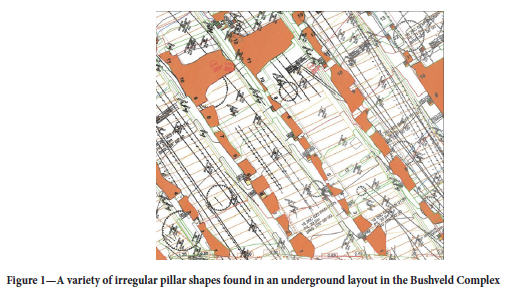
Pillar shape is one of the factors affecting pillar strength (Wagner, 1974; Maritz, 2017; Du et al., 2019), but no clear design methodology exists to account for different pillar shapes. The strength of irregularly shaped pillars is particularly difficult to estimate. Van der Merwe and Madden (2010) provide a methodology to determine the strength of pillars with a parallelogram shape, but this is for only one particular class of pillar shape. Their method is based on correcting for the actual width of the pillar and it does not consider possible premature failure of the corners of pillars with acute angles. Figure 1 illustrates a typical underground layout in the Bushveld Complex of South Africa, showing the variety of pillar shapes that can be found in these layouts. It is not clear what the strengths of these various pillars are, and this highlights the importance of conducting research on this particular problem.
Salamon (1967) described the database used to derive the famous Salamon and Munro (1967) equation for coal pillar strength. He noted that most collieries used pillars with a square cross-section and therefore 'oblong pillars' were excluded from the database. He also stated that 'Actual mine pillars vary in shape and size. Hence, the actual and nominal mining dimensions are likely to differ in practice'. He argued that the adopted factor of safety will largely consider the errors arising from this source. In contrast, when Hedley and Grant (1972) derived their power-law strength formula for hard-rock pillars, the layout geometry and failed pillars they used were elongated rib pillars. They nevertheless only considered the smallest lateral dimension of these pillars in their database. Their argument was: 'This equation refers to square pillars, whereas those in the uranium mines are usually long and narrow. However, it is considered that the strength of such a pillar will not be very much greater than that of a square pillar of width equalling the minimum width of a long pillar' They may have been influenced by Holland and Gaddy (1957), who stated that only the minimum lateral dimension affects the strength of a pillar, while the other dimension has no effect. In summary, the most popular strength equations for pillars used in South African bord-and-pillar layouts was developed for square pillars only.
To consider the strengthening effect of elongated pillars, Wagner (1974) proposed the concept of an 'effective width', which can be calculated from the area and perimeter of a pillar as follows:
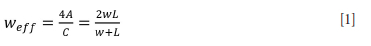
where
A = cross-sectional area of the pillar
C = perimeter of the pillar
w = minimum lateral dimension of the pillar
L = maximum lateral dimension of the pillar.
Equation [1] became known as the 'perimeter rule' and it is widely used in the South African mining industry. It correctly predicts that weff = w if w = L for a square pillar. Wagner's justification for the adoption of Equation [1] is: 'The work described in this paper indicates that the strength of the circumferential portions of a pillar is virtually independent of the width-to-height ratio whereas the strength of its centre increases with increasing ratio' Wagner also noted that Equation [1] predicts that weff approaches a finite value of 2w for very long and narrow pillars. This was also highlighted by Maritz and Malan (2020). To investigate the implication as regards strength for an infinitely long pillar, consider the general form of the power-law strength equation and the effective pillar width, weff:
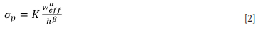
where σp is the strength of the pillar, K is the strength of the rock material in the pillar, h is the height of the pillar, and the exponents α and β need to be calibrated for the particular rock type. If weff =2w for an infinitely long pillar, it follows that:
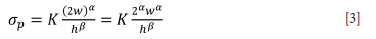
For the Hedley and Grant (1972) formula, α = 0.5 and β = 0.75. From Equation [3], for an infinitely long pillar, the pillar strength can be given as:

It is not clear if the perimeter rule given in Equation [1] is correct as no experimental work was conducted to verify this approximation. Ryder and Ozbay (1990) suggested a shape strengthening factor of the form f = 1.0/1.1/1.2/1.3 for pillars having L/w ratios of 1/2/4/oo. The value 1.3 is slightly less than that predicted by Wagner's perimeter rule for infinitely long pillars (Equation [4]) and was probably adopted as a more conservative approach. Equation [1] is possibly abused in the mining industry as it is also used for pillars with an irregular shape. For example, it is tempting to use the perimeter rule to estimate the strength of the various pillars shown in Figure 1. Its applicability needs to be carefully assessed, however, and this is explored in this paper.
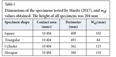
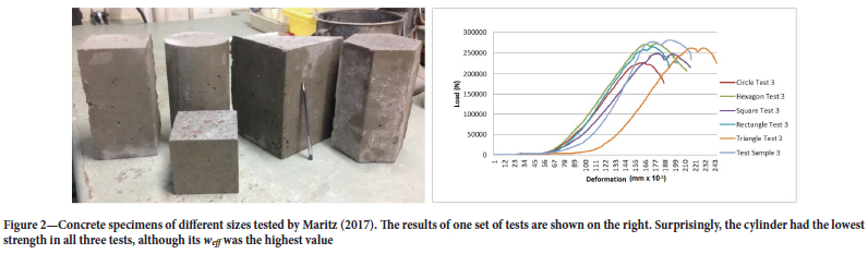
As it is difficult to examine the effect of pillar shape on strength in underground workings, researchers have studied different pillar shapes in the laboratory. A laboratory investigation of a small number of specimens of different shapes was conducted by Maritz (2017). Concrete was used as an artificial rock material to cast different shapes (Figure 2). The sizes of the specimens were carefully selected to ensure that the cross-sectional loading surfaces had similar areas. The w:h ratio was small at 1:2 and the slender nature of the specimens probably affected the results. Even though the cross-sectional areas were constant, the perimeters varied and this resulted in different values of Weff (Table I). According to Equation [2], a difference in strength would therefore be expected. Three sets of tests were conducted, and the results of one of the sets are illustrated in Figure 2. The cylinder was expected to be the strongest shape according to the Weff value, but this was not reflected by the test results. No clear link between the Weff parameter and the specimen strength could be established from this limited number of tests. The small number of tests, the variability of the concrete strength, and the w:h ratio of 1:2 could have affected the results. Additional laboratory work therefore needs to be conducted in the future.
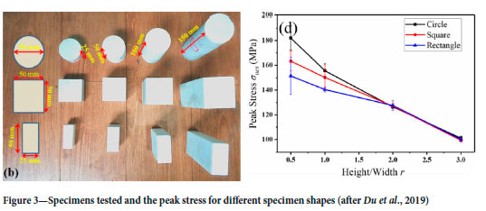
Du et al., (2019) studied the uniaxial strength of circular, square, and rectangular laboratory specimens (Figure 3). Four different height to width/diameter ratios were also tested. They found that the pillars with a lower height to width ratio (r) had a higher bearing capacity (Figure 3). Although it would not be practical, the authors noted that the best shape for mine pillars is cylindrical as this shape has the highest strength (Figure 3). Of particular significance is that the effect of specimen shape is apparent only for the lower height to width ratios (or higher width to height ratios). For the three shapes, it follows from the dimensions given in the figure that: circle weff = 50 mm; square Weff = 50 mm; and rectangle Weff = 33 mm. This would imply that the circle and square configurations are of equal strength according to Equations [1] and [2], but this is only the case at greater height/width ratios. These laboratory experiments provide some evidence that the perimeter rule should be used with caution. The width to height ratio of the specimens seems to play a prominent role, and for slender pillars the minimum lateral dimension should possibly be used in Equation [2], and not Weff.
In contrast, Durmeková et al, (2022) drew no firm conclusions regarding the effect of specimen shape on strength. They tested cylindric specimens (diameters of 20 mm, 35 mm, 50 mm, 70 mm) and cubic and prismatic specimens with a base length of 50 mm. Height to diameter ratios of 1:1 and 1:2 were tested. Four different rock types were also tested. The strength results were highly variable, even for the same rock type.
To summarize, the available laboratory studies do not give conclusive evidence regarding the effect of shape on pillar strength and additional work needs to be conducted. Furthermore, the use of small laboratory samples to infer pillar strengths in mines is also problematic owing to the size effect of rock strength (see e.g. Hoek and Brown, 1980).
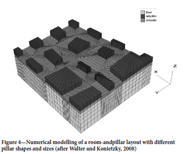
As an alternative to laboratory testing, numerical modelling can be used to study the strength of pillars with different shapes. Figure 4 illustrates the numerical modelling of a room-and-pillar layout. The drawback of finite element or finite different modelling is that it is difficult to build the modelling meshes with irregular pillar shapes. This can be seen in Figure 4 as the pillars are still represented using relatively few straight edges. Most of the modelling done with these codes to study pillar strength considers only a single pillar, often only in two dimensions (e.g. Esterhuizen, 2014). In contrast, displacement discontinuity modelling allows irregular pillar shapes to be simulated, as illustrated in Napier and Malan (2021). This approach is explored further in this paper.
In summary, historical studies do not give clear evidence regarding the effect of pillar shape on strength, and additional research is required. It seems that the width to height ratio of the pillars also play a role and this is not considered by the perimeter rule. This paper describes a numerical modelling and analytical study, using a limit equilibrium model, to investigate the effect of pillar shape.
Insights from an analytic limit equilibrium solution of pillar strength
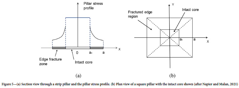
Napier and Malan (2021) derived an analytic model of pillar failure for a long strip pillar and a square pillar (Figure 5).
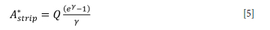
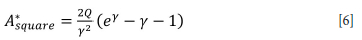
A limit equilibrium model is assumed for the two pillar shapes shown in Figure 5. The width of the square pillar and the minimum width dimension of the strip pillar is w=2a. The fracture zones on the edges of the pillars are in a state of equilibrium and the vertical extent of the fracture zone is bounded by parting planes at the hangingwall and footwall contacts. Using these assumptions and a failure model for the seam material, the scaled average pillar stresses A*strip and A*square for the two pillars are given by Equations [5] and [6]. Note that these equations are valid at the point when the intact core becomes completely fractured and, depending on the parameters selected, do not necessarily indicate the peak strength of the pillars (see Napier and Malan, 2021). They are nevertheless still useful to compare the relative strengths of the two pillar shapes.
For a strip pillar:
For a square pillar:
where
and
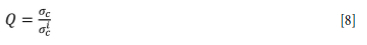
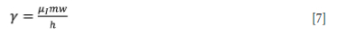
For Equations [7] and [8], μ1 is the friction coefficient at the interface of the fractured seam and the host rock, m is the slope in the residual limit equilibrium strength envelope, alc is the intact rock uniaxial strength, and ac is the residual strength after failure. Note that the parameters γ and Q are dimensionless and therefore A*strip and A*square are also dimensionless. Additional information can be found in Napier and Malan (2021).
To gain insight into the increase in strength for the strip pillar in relation to the square pillar for the same width of w, divide Equation [5] by Equation [6]. This gives:
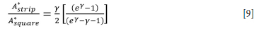
The assumption in the previous section of adopting a perimeter rule and the Hedley and Grant power-law in Equation [4] indicated that an infinitely long strip pillar will be 1.414 times stronger than a square pillar of the same width. Equation [9], based on a limit equilibrium model, indicates a more complex scenario where the increase in strength for the rib pillar compared to the square pillar will also be based on the w/h ratio (included in the γ parameter in Equation [7]). The coefficient of friction μ1 and the slope parameter m in the strength envelope for the failed pillar material also play a role. Equation [9] is plotted in Figure 6 as a function of the w/h ratio.
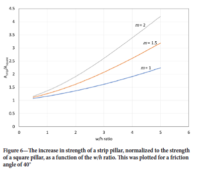
Figure 6 indicates that the increase in strength for the infinitely long strip pillar in relation to the square pillar is a function of the w/h ratio and not simply a constant as given by Equation [4]. Interestingly, the model predicts at a small width to height ratio, wh<1, (or a large height to width ratio) that (A*strip/A*Square) ~ 1. There is therefore no increase in strength for an infinitely long strip pillar compared to a square pillar of the same width as the minimum dimension of this strip pillar. This is in qualitative agreement with the results in Figure 3, where there is no difference in the tested strength for slender pillars, regardless of pillar shape. Based on these results, care should be exercised when attempting to use the perimeter rule for slender pillars. Dolinar and Esterhuizen (2007) also noted that there is little or no increase in strength for an increase in pillar length for slender pillars. They conducted FLAC3D modelling on limestone pillars of different lengths and heights and developed equations to describe the modelled strength behaviour.
They found that for wh<0.66, there is little or no increase in strength with increasing pillar length. Only for the more 'squat' pillars is there a significant increase in strength with pillar length.
Numerical simulation of the effect of pillar shape on pillar strength
The complex pillar shapes illustrated in Figure 1 and the effect of the width to height ratio discussed in the previous section highlight potential difficulties associated with using the perimeter rule. This was explored further by the use of numerical modelling.
Overview of the TEXAN code and the limit equilibrium model
To simulate the effect of pillar shape on pillar strength, a novel approach using a displacement discontinuity boundary element code, TEXAN, was explored (Napier and Malan, 2007). Displacement discontinuity codes cannot simulate the failure of the pillars, but the inclusion of a limit equilibrium constitutive model in TEXAN allows for the modelling of on-seam failure. The model will not be described here and the reader is referred to the numerous papers already published on this topic (e.g. Napier and Malan, 2018, 2021; Couto and Malan, 2022). The host rock is assumed to be an isotropic, homogeneous, elastic medium. TEXAN is particularly well suited to simulate the shallow bord-and-pillar layouts in the Bushveld Complex in South Africa as it was designed to represent irregular pillar shapes.
Regarding the limit equilibrium model TEXAN assumes that the pillar is bound by frictional parting planes at the contacts with the hangingwall and footwall. By considering the force equilibrium of a slice of rock in the fractured edge of the pillar, it is possible to construct a differential force balance for the average seam-parallel and seam-normal tractions. The solution of the governing differential equation indicates that the tractions increase in an exponential fashion towards the intact core of the pillar. For a tabular layout problem, with irregular pillar shapes discretized using triangular elements, a 'fast marching solution' to determine the seam-parallel stress is used. A number of assumptions are made in the TEXAN program; for example it is assumed that the seam-parallel stress gradient direction is perpendicular to the adjacent element edge at the excavation boundary. Napier and Malan (2021) provide a detailed description of this solution scheme.
Table II lists the values of the limit equilibrium model parameters used for the modelling described in this paper. Additional information regarding these parameters can be found in Napier and Malan (2021)
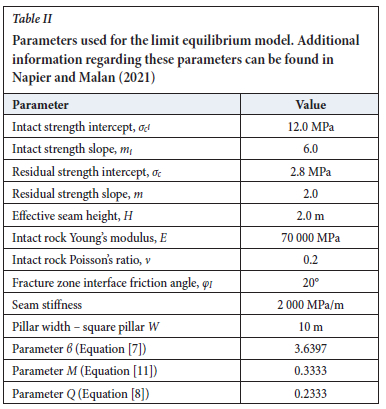
The model parameters given in Table II were selected arbitrarily as the objective was to investigate the effect of shape on strength and the only requirement was that the progressive failure of the pillar, from limited failure at the edges of the pillar to complete failure of the core, could be simulated for the imposed incremental loads. The same parameters were used to simulate the different pillar shapes. Of interest is that the limit equilibrium model implemented in TEXAN can predict both a softening and a hardening response after failure, depending on the choice of parameter values (Napier and Malan, 2021). The condition for immediate softening after the onset of failure for a square pillar is given by:
where parameters γ and Q were already defined in Equations [7] and [8], and
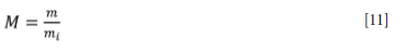
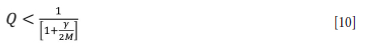
The parameters H,m,mi,σc,σic are defined in Table II where w is the pillar width of a square pillar and μι = tanφi. Furthermore, the condition that the final average pillar stress for a completely failed pillar is greater than the average pillar stress at the onset of failure is given by (Napier and Malan, 2021):
For the parameters given in Table II,  0.2333 - Q. The condition given by Equation [10] is therefore not met and the parameters will not give immediate softening after failure. Furthermore, y2/[2(eY - γ - 1)] = 0.1981 < 0.2333 = Q. The condition in Equation [12] is met and therefore the final average pillar stress for a completely failed pillar will be greater than the average pillar stress at the onset of failure. The load-deformation curves for the pillars presented later correctly reflect these conditions (see for example the curve for weff = 16.7 in Figure 14). The specimen continues to strain harden after the initial failure and the final strength value is greater than at this initial point of failure. Although similar model parameters were used for the results in Figure 13, the loading increments used for the model were too large and the point of initial failure is not indicated correctly - it should be lower. The method of applying the load increments in the model is described in the next section.
Numerical modelling geometries
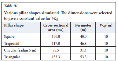
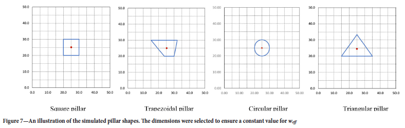
As a first experiment, the numerical model was used to determine whether different shapes with similar Weff values could have similar peak strengths. Four pillar shapes were generated with the dimensions given in Table III. The pillar shapes are shown in Figure 7. The Weff parameter was calculated using Equation [1]. Interestingly, the triangular pillar has a substantially larger area than the other specimens to meet the required Weff value.
The pillar height was 2 m as indicated in Table II. This gives a W:h ratio of 5 for the square pillar. These specimens can therefore be considered as 'squat' pillars and it is expected that the pillar shape will make a difference in terms of strength when considering the information discussed above.
Various pillar shapes were simulated. The dimensions were selected to give a constant value for Weff.
The geometries were discretized using triangular elements of a size approximately 0.08 m2. The mesh for the triangular pillar is shown in Figure 8. As this was simulated using a displacement discontinuity code, the pillars had to be positioned in a 'mined stope' and an arbitrary size of 50 m χ 50 m was selected. As a crude method to gradually increase the stress on the pillars, the depth of the excavation was increased in successive runs and this enabled a stress-strain curve of the pillars to be generated.
The effect of elongation of the square pillar was studied in a second set of simulations. The geometries are shown in Figure 9.
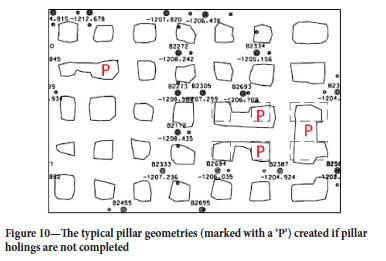
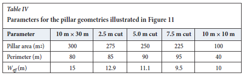
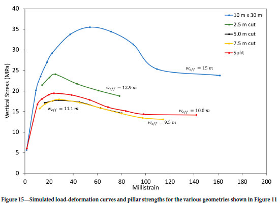
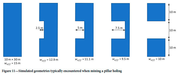
The third pillar geometry simulated is the one frequently encountered underground in bord-and-pillar layouts where pillar holings were not completed. This is illustrated in Figure 10 for an actual layout. As a simplification for the modelling, a 10 m χ 30 m pillar, which is incrementally mined in the centre holing, was simulated (Figure 11). The face advance was 2.5 m increments until the pillar was split into two 10 m χ 10 m pillars. Note how the Weff parameter decreases during this pillar splitting process. Table IV summarizes the change in pillar parameters for the various steps.
Numerical modelling results
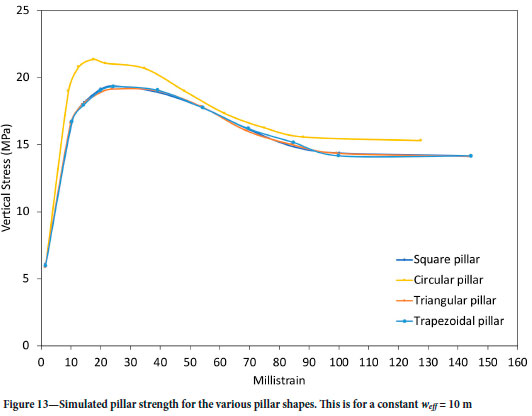
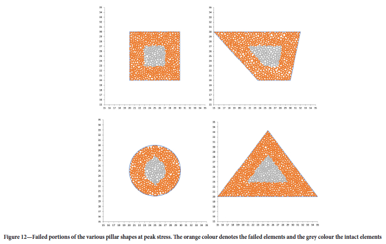
The first results are for the different pillar shapes with a similar weff (see Figure 7). Figure 12 illustrates the failed sections of the various pillar shapes. Interestingly, the intact core for each pillar assumed the original outline shape of the pillar. The load-deformation curve for these four pillars are given in Figure 13. The circular pillar is stronger (similar to that observed by Du et al., 2019), but the peak strengths of the other three pillars are almost identical. According to Equations [1] and [2], this should have been expected as the weff values of the three pillars are identical. The circular pillar is stronger, however, in spite of a similar weff, possibly because the absence of sharp corners delays the onset of fracturing and hence imparts a greater load-bearing capacity.
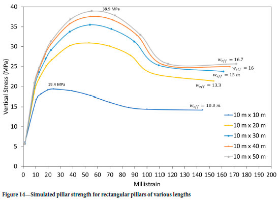
In contrast to the constant weff simulated in Figure 12, the increase in length of a rectangular pillar resulted in an increase in weff. The results of simulating the geometry in Figure 9 are presented in Figure 14. As expected the peak strength increases with an increase in value for Weff. This is an important finding as the limit equilibrium model indicates the expected increase in strength for the rectangular pillars. The analytical model in Figure 6 also indicated this increase in strength for an infinitely long strip pillar versus a square of the same width for large w/h ratio pillars. For the parameters used, the modelling predicts an increase of peak strength from 19.4 MPa for the square pillar to 38.9 MPa for the 50 m long pillar. This is an increase in strength of approximately 2 for the rectangular pillar - higher than the 1.414 predicted by the perimeter rule for an infinitely long pillar.
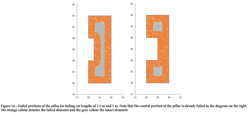
The third set of simulations investigated the effect of the holing of the pillar illustrated in Figure 11. The simulated stress profiles are illustrated in Figure 15. Note how the simulated peak strength of the pillar decreases as the Weff decreases during the holing process. As the cut progressed to a depth of 5 m, the 'bridge' between the remaining two future square pillars became completely fractured (see Figure 16), and therefore the peak strengths for the pillar at cut distances of 5 m and 7.5 m are identical. This is not correctly predicted by the different Weff values for these two geometries. The use of the Weff value as a parameter to calculate pillar strength for irregular pillars similar to the scenario depicted in Figure 11 is therefore questionable. Numerical modelling seems to be an attractive alternative, provided an accurate calibration of the limit equilibrium model can be done for the conditions encountered in different geotechnical areas.
Conclusions
This paper is a preliminary study of the effect of pillar shape on pillar strength. A literature survey indicated that little is known about this topic and it has mostly been ignored in past research studies. The perimeter rule is widely adopted for non-square pillars, but its applicability for arbitrary pillar shapes has never been tested.
An analytical limit equilibrium failure model of a square and a strip pillar indicated that for slender pillars (small width to height ratios), the strength of a long rib pillar is essentially similar to that of a square pillar (for geometries where the width of the square pillar is identical to the smallest lateral dimension of the rib pillar). In contrast, the solutions indicate that long rib pillars with a large width to height ratio show a substantial increase in strength compared to the square pillar. This is confirmed by laboratory studies which indicated that for slender pillars, the pillar shape has almost no effect.
The study indicated that the displacement discontinuity modelling approach, using a limit equilibrium failure model, is well suited to simulate the effect of pillar shape. It can, for example, predict the increase in strength for elongated rectangular pillars, and the results qualitatively agree with the increase in strength predicted by the perimeter rule for the relatively 'squat' pillars modelled. This study highlighted, however, that the perimeter rule should not be used for pillars with a complex or irregular shape. One such example is 'elongated' pillars where the holing between adjacent square pillars was not completed. Sections of these pillars may be fractured through completely and not carry load. On the mine plans, these failed sections are still indicated and this will affect the area and perimeter calculations used for the perimeter rule.
The limit equilibrium constitutive model is a valuable addition to displacement discontinuity modelling. This can be used to simulate the effect of shape on pillar strength, but careful calibration of the model is required. Assigning material properties to the failed rock on the pillar edges is particularly challenging.
Additional laboratory studies of the effect of pillar shape are required to confirm the results obtained from numerical modelling approaches.
Acknowledgements
This work forms part of the PhD study of Jannie Maritz at the University of Pretoria.
References
Couto, P.M. and Malan, D.F. 2022. A limit equilibrium model to simulate the large-scale pillar collapse at the Everest Platinum Mine. Rock Mechanics and Rock Engineering, vol. 56. pp. 183-197. https://doi.org/10.1007/s00603-022-03088-z [ Links ]
Dolinar, D.R. and Esterhuizen, G.S. 2007. Evaluation of the effect of length on the strength of slender pillars in limestone mines using numerical modeling. Proceedings of the 26th International Conference on Ground Control in Mining, Morgantown, WV: West Virginia University. pp. 304-313. [ Links ]
Du, K., Su, R., Tao, M.,Yang, C., Momeni, A., and Wang, S. 2019. Specimen shape and cross-section effects on the mechanical properties of rocks under uniaxial compressive stress. Bulletin of Engineering Geology and the Environment, vol. 78. pp. 6061-6074. [ Links ]
Durmeková, T., Bednarik, M., Dikejová, P., and Adamcova, R. 2022. Influence of specimen size and shape on the uniaxial compressive strength values of selected Western Carpathians rocks. Environmental Earth Sciences, vol. 81. p. 247. doi: 10.1007/s12665-022-10373-1 [ Links ]
Esterhuizen G.S. 2014. Extending empirical evidence through numerical modelling in rock engineering design. Journal of the Southern African Institute of Mining and Metallurgy, vol. 114. pp. 755-764. [ Links ]
Hedley, D.G.F. and Grant, F. 1972. Stope-and-pillar design for the Elliot Lake Uranium Mines. CIM Bulletin. vol. 65. pp. 37-44. [ Links ]
Hoek, E. and Brown, E.T. 1980. Underground Excavations in Rock. Institution of Mining and Metallurgy, London. [ Links ]
Holland, CT. and Gaddy, F.L. 1957. Some aspects of permanent support of overburden on coal beds. Proceedings of the West Virginia Coal Mining Institute. pp. 43-65. [ Links ]
Maritz, J. 2017. Preliminary investigation of the effect of areal shape on pillar strength. Proceedings of ISRM AfriRock - Rock Mechanics for Africa. Paper no. ISRM-AFRIROCK-2017-012 International Society for Rock Mechanics, Lisbon. [ Links ]
Maritz, J.A. and Malan, D.F. 2020. Numerical assessment of the perimeter rule for pillar strength calculations. Proceedings of the ISRM International Symposium EUROCK2020. International Society for Rock Mechanics and Rock Engineering , Lisbon. [ Links ]
Napier, J.A.L. and Malan, D.F. 2007. The computational analysis of shallow depth tabular mining problems. Journal of the Southern African Institute of Mining and Metallurgy, vol. 107. pp. 725-742. [ Links ]
Napier, J.A.L. and Malan D.F. 2018. Simulation of tabular mine face advance rates using a simplified fracture zone model. International Journal of Rock Mechanics and Mining Sciences, vol. 109. pp 105-114. [ Links ]
Napier, J.A.L. and Malan D.F. 2021. A limit equilibrium model of tabular mine pillar failure. Rock Mechanics and Rock Engineering, vol. 54. pp. 71-89. [ Links ]
Ryder, J A and Ozbay, M U. 1990. A methodology for designing pillar layouts for shallow mining. Proceedings of the International Symposium on Static and Dynamic Considerations in Rock Engineering, Swaziland. International Society for Rock Mechanics and Rock Engineering, Lisbon. [ Links ]
Salamon, M.D.G. 1967. A method of designing bord and pillar layouts. Journal of the South African Institute of Mining and Metallurgy, vol. 68. pp. 68-78. [ Links ]
Salamon, M.D.G. and Munro, A.H. 1967. A study of the strength of coal pillars. Journal of the South African Institute of Mining and Metallurgy, vol. 68. pp. 55-67. [ Links ]
Van der Merwe, J.N. and Madden, B.J. 2010. Rock Engineering for Underground Coal Mining. Special Publications Series no, 8. Southern African Institute of Mining and Metallurgy, Johannesburg. [ Links ]
Wagner, H. 1974. Determination of the complete load-deformation characteristics of coal pillars. Proceedings of the 3rd ISRM Conference, Vol IIB, Advances in Rock Mechanics. International Society for Rock Mechanics and Rock Engineering , Lisbon. pp. 1076-1081. [ Links ]
Walter, K. and Konietzky, H. 2008. Room pillar dimensioning for gypsum and anhydrite mines in Germany. Proceedings of the Conference on Advances in Mining and Tunneling 2008, Hanoi, Vietnam. Publishing House for Science and Technology, Hanoi. pp. 349-362. [ Links ]
 Correspondence:
D.F. Malan
Email: francois.malan@up.ac.za
Received: 26 Nov. 2022
Revised: 20 May 2023
Accepted: 23 May 2023
Published: May 2023

