


Services on Demand
Article
 English (pdf)
 Article in xml format
 Article references
Indicators

Related links
-
 Cited by Google
 -
 Similars in Google
Share

 Permalink
Journal of the Southern African Institute of Mining and Metallurgy
On-line version ISSN 2411-9717
Print version ISSN 2225-6253
J. S. Afr. Inst. Min. Metall. vol.123 n.5 Johannesburg May. 2023
http://dx.doi.org/10.17159/2411-9717/2452/2023
PILLAR DESIGN EDITION
A study of backfill confinement to reinforce pillars in bord-and-pillar layouts
D. Ile; D.F. Malan
Department of Mining Engineering, University of Pretoria, South Africa
SYNOPSIS
This study explores the use of backfill in hard rock bord-and-pillar mines to increase the pillar strength and extraction ratio at depth. The use of backfill will also minimize the requirement for tailings storage on surface and the risk of environmental damage. A literature survey indicated that backfill is extensively used in coal mines, but rarely in hard rock bord-and-pillar mines. To simulate the effect of backfill confinement on pillar strength, an extension of the limit equilibrium model is proposed. Numerical modelling of an actual platinum mine layout is used to illustrate the beneficial effect of backfill on pillar stability at greater depths. The magnitude of confinement exerted by the backfill on the pillar sidewalls is unknown, however, and this needs to be quantified using experimental backfill mining sections equipped with suitable instrumentation.
Keywords: backfill, bord-and-pillar, pillar strength, limit equilibrium model.
Introduction
There is still uncertainty regarding the strength of the pillars in the shallow tabular excavations of the Bushveld Complex (e.g. Malan and Napier, 2011; Couto and Malan, 2022). The Hedley and Grant (1972) empirical formula is typically used to estimate pillar strength. Historically, one-third of the laboratory uniaxial compressive strength value of the pillar material was used for the K-value in the formula for South African mines. Stacey and Page (1986) suggested the use of the DRMS (design rock mass strength; Laubscher, 1990) as the K-value. Many stable layouts have been designed using these formulae. The lack of precise knowledge regarding pillar strength nevertheless causes a conservative approach to be adopted in many cases. This, in conjunction with the adoption of a factor of safety of 1.6, as used in the coal mining industry (Ryder and Jager, 2002), possibly resulted in oversized pillars. As the mining depths increase, the pillar sizes will increase further. This will be detrimental to the extraction ratio and the profitability of the mines in future.
The placement of backfill in underground stopes presents an opportunity to minimize the damage that mining causes to the environment (Zhang et al., 2019). Tailings production is inherent to minerals processing. The International Council on Mining and Metals (ICMM, 2022) recently published a Tailings Reduction Roadmap. The motivation for this study was the catastrophic tailings dam failures at Mount Polley in Canada (2014), Samarco in Brazil (2015), and Brumadinho in Brazil (2019). South Africa is not immune to this type of failure, as illustrated by the Merriespruit disaster (1994) and the more recent failure of the tailings dam at the Jagersfontein mine.
The ICMM investigated technologies that can minimize tailings production. Their proposals focused on the following aspects.
> Precision geology: Geological techniques are needed to better characterize the orebody to maximize ore production and minimize the mining of waste rock. This will reduce the amount of tailings generated.
> Precision mining: This also aims to reduce the mining of waste rock and the amount of tailings generated.
> Precision segregation: This focuses on better segregation technology to optimize mineral recovery and produce more benign tailings.
> In-situ recovery: Leaching techniques can possibly be used to optimize mineral recovery and eliminate the production of waste rock.
> Tailings enhancement: This requires the creation of value from tailings to minimise the requirement; for tailings storage.
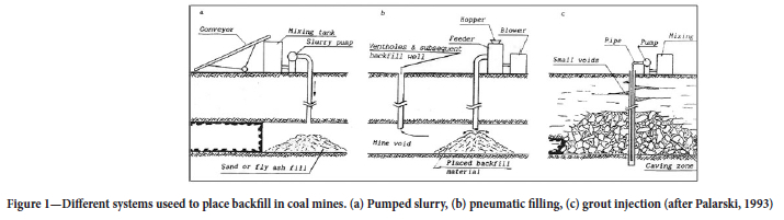
The use of tailings to reinforce pillars and enable pillar sizes to be reduced is part of the last aspect, which is explored in this paper. The increased profitability of the mine when using smaller pillars may offset the additional infrastructure and maintenance required for using backfill in underground workings. Figure 1 illustrates some of the systems used in coal mines to place the backfill. These methods are beyond the scope of this paper and the focus will be on the effect of backfill confinement on pillar strength.
The effect of depth on extraction ratio in bord-and-pillar layouts
As an illustration of the detrimental effect of depth on the extraction ratio in bord-and-pillar workings, consider the layout shown in Figure 2. A similar approach was described by Malan and Esterhuyse (2021), but a more general equation is derived below. The dip of the layout is considered to be 0° and the extent of mining in the two lateral directions is considered to be very large. Tributary area theory (TAT) can therefore be used as a good approximation to calculate the stresses acting on the pillars (Ryder and Jager, 2002).
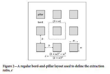
The average pillar stress (APS) for the layout in Figure 2 is given by Ryder and Jager (2002) as:
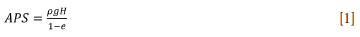
where
ρ = density of the rock
g = gravitational acceleration
e = extraction ratio
H = depth of mining
Equation [1] can be rearranged to give the extraction ratio as:

To prevent failure of the pillars, a factor of safety (Sf) is adopted for the design, and this is given by:
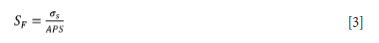
where σs is the pillar strength. This can be rearranged as:

Equation [4] can be inserted in Equation [2] to give:

As described above, a power-law strength formula is typically used to determine the pillar strength in South African mines. The general form of the power-law can be written as (Malan and Napier, 2011):
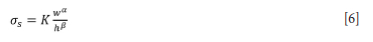
where K is the strength of the rock material in the pillar, w is the pillar width, and h is the pillar height. The values for the exponents α and β must be determined for the particular pillar type. Equation [6] can be inserted in Equation [5] to give:

where
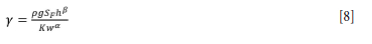
From Equation [7], the extraction ratio e is therefore a simple decreasing linear function of the depth, H, and the rate of decrease is dependent on the parameter γ. This parameter is a function of the assumed pillar strength, the overburden density, and the factor of safety and should preferably be as small as possible. From Equation [8], there are not many options to increase the extraction ratio. For example, the mining height can be reduced, but this is not always feasible owing to the reef width or the minimum height limitations imposed by the equipment used. A further subtle aspect of Equations [7] and [8] is that the extraction ratio can be increased by increasing the pillar width (increasing the pillar strength), which will enable the bord spans to be increased. However, this is not always feasible.
The decrease in extraction ratio predicted by Equation [7] is illustrated in Figure 3 for a typical bord-and-pillar mine in the Bushveld Complex. The factor of safety for the pillars is maintained at a value of 1.6 g = 9.81 m/s2, the overburden density is 3000 kg m3, the mining height is assumed to be 2 m, and the pillar width is maintained at 7 m. The Hedley and Grant pillar strength formula is assumed and therefore α = 0.5 and β = 0.75. If the UCS of the laboratory samples is 100 MPa, when adopting the classical rule for the strength of the pillar material it follows that K = 1/3 UCS = 33 MPa.
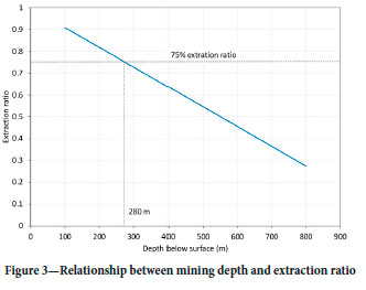
From Figure 3 it follows that an extraction ratio of 1.6 can be maintained only up to a depth of 280 m. This is problematic for mines planning to implement mechanized bord-and-pillar operations at greater depths. Research is currently being conducted to determine better estimates of pillar strength so as to investigate if higher extraction ratios can be maintained at greater depths and with pillars containing weak material (Watson et al., 2022, Couto and Malan, 2022). An alternative is to use methods to artificially increase the pillar strength. This paper describes a study of using backfill to reinforce the pillars. Smaller pillars could then possibly be used at greater depths and the extraction ratio increased.
Examples of the use of backfill to reinforce or extract pillars
Backfill is commonly used as mine support. For example, in South Africa it is used for regional and local support in deep gold mine stopes. It is also used in shallow operations to enable multi-reef extraction (see e.g. Squelch, 1993; Ryder and Jager, 1999). There is a vast amount of literature available on backfill and the types of backfill, but the objective of this paper is not to summarize these studies. The focus is on exploring the use of backfill to increase pillar strength for bord-and-pillar mining layouts. From a literature study on this narrow aspect, it appears that the use of backfill to reinforce pillars and minimize environmental damage is mostly confined to the coal mining sector. Extensive use is made of this method in the Chinese coal mines, as described by Zhang et al. (2019). It appears the backfill is mostly used in conjunction with high extraction mining methods such as longwalling, with the backfill being placed in the goaf area. Apart from the environmental aspects, the use of backfill is mainly for control of surface subsidence. The Polish coal mining industry also uses backfilling in their longwalls, as described by Palarski (1994). Tailings backfill was introduced as early as 1893 in these mines. The main reasons for backfilling are to support the roof, to prevent movement of the rock mass, and to eliminate the fire hazard in old mine workings.
The backfill methods described above are employed to increase the stability of longwall stopes and prevent or minimize subsidence. Only a few studies of using backfill to enhance pillar strength could be found. For South African coal mines, backfilling was studied as a method to stabilizing under-designed bord and pillar layouts and to achieve higher recoveries by increasing pillar height in thick seam conditions (Galvin and Wagner, 1982; Buddery, 1985). This work is described in more detail later.
Salamon and Oravecz (1976) describe the benefits of ash, sand, or waste filling in coal mines. Practical experience indicated that filling can arrest the gradual deterioration of pillar areas. As the backfill is typically not in contact with the roof, the fill will not transmit any pressure between the roof and floor. The load on the pillars is therefore not reduced. The benefit of the fill is the lateral pressure it exerts on the pillar sidewalls, which can increase the strength of the pillars. The more important benefit arises when the pillars are failing and undergoing significant lateral expansion. The effectiveness of the fill will depend on the compaction of the material and the height of the fill in relation to pillar height. Hydraulically transported material may therefore be more effective than fill introduced in a dry state. In terms of fill height, the dilation of pillars is typically the greatest at mid-height and the fill height must be greater than this. Salamon and Oravecz (1976) recommended that the fill height should extend to at least two-thirds of the mining height. Donovan (1999) studied the effects of backfilling in coal mining and derived revised pillar strengths that arose from the confining effect of backfill. An increase in extraction from 3% to 32% was predicted.
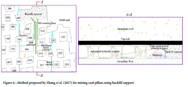
Zhang et al. (2017) proposed a method to extract coal pillars using backfill support (Figure 4). Two rows of pillars are mined incrementally. The backfill is transported to the area using a belt conveyer and placed in the goaf using a so-called 'high-speed power material thrower'. A bulldozer is used to compact the backfill. It is not clear if this method was successfully implemented in practice.
Kostecki and Spearing (2015) used FLAC3D modelling to investigate the effect of various fill heights on pillar strength. The study indicated a 40% increase in pillar strength when a cohesive backfill material is used and 75% of the mining height is filled. Shen et al. (2017) conducted FLAC3D modelling of coal pillars to study the effect of backfill consisting of non-cohesive fly ash grout in a typical bord-and-pillar mine. A single pillar with various fill heights was simulated. The stress/strain behaviour of the pillar changed from strain softening at low fill percentages to strain hardening at fill percentages above approximately 70%. Mo et al. (2018) used FLAC2D modelling to quantify the effect of backfilling on pillar strength in highwall mining. The simulated behaviour of pillars was found to vary with the type and percentage of backfill placed as well as the pillar width to height ratio. For cohesive backfill, 75% backfilling resulted in a significant increase in peak pillar strength, especially for pillars with lower width to height ratios. For non-cohesive backfill, the effect of the backfill was less pronounced.
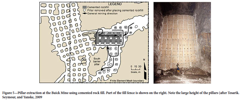
An example of successful pillar extraction in a hard rock mine using backfill is given by Tesarik. Seymour, and Yanske (2009). Figure 5 illustrates the test area, with a size of approximately 107 m χ 69 m, in the Buick Mine, St Louis, Missouri. The pillar heights were 14 m to 19 m and the widths were approximately 9 m. The pillars were slender with a width to height ratio of less than 1. These pillar dimensions are therefore not comparable to the pillar sizes in the bord-and-pillar operations in the Bushveld Complex. Prior to extraction, a fill fence was constructed around the pillars (Figure 5). Cemented rock fill was used and the numbered pillars were successfully mined. The so-called 'trapped pillars' were excavated using an access drift in the footwall. This is not deemed a feasible method for the mines in the Bushveld Complex, however, as the pillar volumes are much smaller and building the fill fence may be problematic for a large area. The trapped pillars can also not be accessed via footwall development.
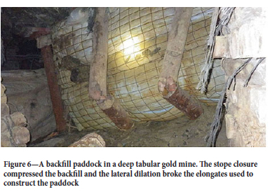
In the South African hard rock mining industry, backfill is typically only used in the deep gold mines to reduce stope closure and the associated energy release rates, and to minimize the risk of rockbursts (Jager and Ryder, 1999). A typical backfill paddock in one of these tabular stopes is illustrated in Figure 6. Most historical studies of backfill in the tabular gold mine stopes focused on the reef-normal closure (to reduce the energy release rates) and the stress generated in this direction.
For the application of backfill to strengthen the pillars in a bord-and-pillar layout, the horizontal stress component is important. The convergence in these layouts is very small and therefore almost no vertical stress will be generated in the backfill apart from the gravitational component owing to the weight of the material. The panel deformation will also occur before the backfill is placed and therefore it can be assumed that no closure will act on the backfill. This negates the need for tight filling and backfill contact with the hangingwall is not required. Salamon and Oravecz (1976) noted that the beneficial effect of backfill in bord-and-pillar layouts is due to the pressure that it exerts on the pillar sidewalls, thereby increasing the strength of the pillars.
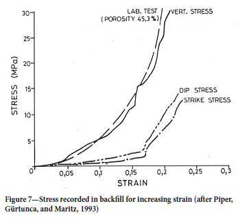
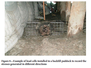
Figure 7 illustrates measurements conducted inside backfill in a gold mine. The instrumentation recorded the vertical stress as well as the lateral stress in the dip and strike directions. An example of typical backfill load cell instrumentation is shown in Figure 8. The stress in the lateral directions became meaningful only if the strain in the vertical direction exceeded approximately 0.1. This implies that for a bord-and-pillar layout with a mining height of 2.5 m, at least 250 mm of closure needs to be recorded after the backfill is placed. This is not observed for the hard rock bord-and-pillar layouts in the Bushveld Complex, except for the rare cases where large-scale pillar collapses occur (Couto and Malan, 2022). In an experimental pillar mining set-up where some of the pillars failed and the spans were substantially increased (see Napier and Malan, 2021), the maximum recorded closure was in the order of 12 mm. The mining height was 2.5 m and the strain on the backfill was therefore only be 5 millistrains. A further problem with backfill in flat-dipping tabular stopes is that good contact with the hangingwall cannot be achieved.
Blight and Clarke (1983) investigated the relationship between the lateral and vertical stress for soft and stiff fills. The ratio of lateral to vertical stress was found to vary from 0.1 to 0.45 for stiff fills and 0.4 to 0.7 for soft fills. They noted that backfill can therefore support pillars, but conceded that significant vertical strains are necessary to develop the lateral stress. As the vertical strains are very low in shallow bord-and-pillar operations, a different approach will have to be used to estimate the lateral confinement exerted by the backfill on the pillars. Rankine theory is useful as a first approximation, and is discussed in the next section.
Estimating the pillar confinement exerted by backfill
The historical measurements of horizontal stress in backfill in the South African gold mines were not sensitive enough to determine the magnitude of the stress at small strains. Some estimation of the horizontal stress therefore needs to be made for the numerical modelling described in the next section. For coal pillars and ash filling, Buddery (1985) estimated that the strain in the ash fill would be 1.7 χ 10-3 and this translated to a confinement stress of 0.05 MPa when assuming a modulus of 27 Mpa, and 0.51 MPa for a modulus of 300 MPa. As a crude estimate of the increase in pillar strength, Buddery assumed a 'Coulomb failure criterion' for these pillars and demonstrated that a 13.6% increase in pillar strength is possible for the higher modulus and confining stress. The application of this failure criterion and the associated assumptions are highly uncertain, however.
Galvin and Wagner (1982) studied the use of ash filling to improve strata control in coal bord-and-pillar workings. For the notation shown in Figure 9, the fill reaction stress (pillar confinement stress), of, is given by:
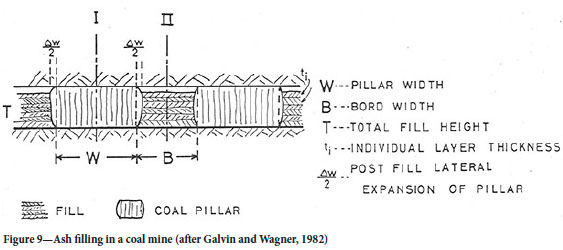

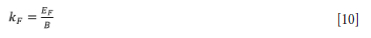
where eF is lateral fill strain, EF is the fill modulus, and the fill stiffness, kF (MN/m3) is given by:
From Equation [9] it follows that a large pillar confinement stress can be achieved only if the fill stiffness is high. From Equation [10], this stiffness is proportional to the fill modulus, Ef, and inversely proportional to the bord width. The authors note that the dilation of failing pillars is greatest at mid-height and therefore the fill depth must be more than the half the pillar height, and preferably two-thirds of this height. Galvin and Wagner (1982) describe an underground experiment where ash filling was used. The original factor of safety of the pillars was 1.3. Top-coal mining was done to decrease the width to height ratio of the pillars and ash fill was placed. The upper 3 m portions of the pillars were not covered by the fill. Although the final factor of safety decreased to 0.6, the area remained stable. The upper, uncovered parts of the pillars underwent only minimal slabbing. The lateral stress in the ash fill was measured at 0.05 MPa. Interestingly, this is similar to the stress estimated by Buddery (1985) for a fill modulus of 27 MPa.
An alternative estimate of the pillar confinement stress can be made using calculations of lateral earth pressure (e.g., Rankine, 1856; Pantelidis, 2019). Lateral earth pressure is the pressure that soil exerts in the horizontal direction. This pressure is important for the design of geotechnical engineering structures such as retaining walls. The coefficient of lateral earth pressure, K, is defined as
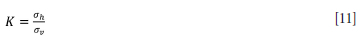
where σh is the horizontal or lateral stress and σv is the vertical stress. As the vertical stress in soil is given by σv = yh where γ is the density of the soil and h is the depth of the soil, Equation [11] can be written as
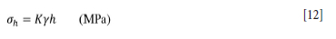
Equation [12] results in the pressure distribution shown in Figure 10. The vertical stress (and therefore the horizontal stress) gradually increases with soil depth. At the surface of the soil, the stress will be zero, increasing linearly to a maximum value at the bottom of the retaining wall.
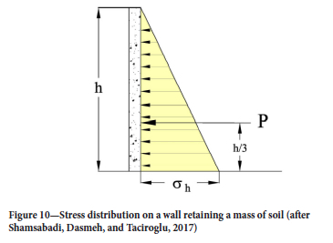
The equivalent lateral earth force, shown in Figure 10 as P, which acts one-third of the height up the wall, can be obtained by integrating Equation [12] along h:

There are three different values for K, namely:
> K0 = 'At rest' lateral earth pressure coefficient. This is for the in-situ lateral pressure of soil.
> Ka = 'Active' lateral earth pressure coefficient. This is for soil at the point of shear failure owing to unloading in the lateral direction. This is when the retaining wall, for example, moves away from the soil mass.
> Kp = 'Passive' lateral earth pressure coefficient. This is for a soil mass that is externally forced inward. The soil mass is therefore at the point of incipient shear failure owing to loading in the lateral direction.
The applicability of this theory for backfill against a pillar is not clear and it is hypothesised that the K0 parameter will be important in cases where there is little or no pillar dilation. For extensive pillar failure and dilation, the Kp parameter may be more important. This is speculation, however, and underground measurements in backfill will be required to determine the actual lateral confinement exerted by the backfill. The three coefficients mentioned above can be calculated using the following equations (Pantelidis, 2019):
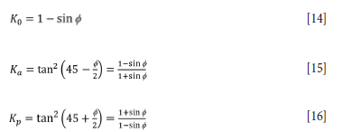
If the friction angle of the backfill is assumed to be 30°, then by using Equation [14], the at rest lateral earth pressure coefficient is calculated to be K0 = 0.5.
Furthermore, as a simplification, if the force P (from Equation [13]) acts along a pillar of height h, the average confinement stress along the pillar face is
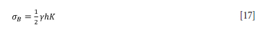
Note that this equation is a simplification as it assumes the original graded distribution of horizontal stress in Figure 10 is now a constant average value along the edge of the pillar. This approximation may not be correct and needs to be verified by underground measurements in actual backfill placed against a pillar. If the density of backfill is 1750 kg/m3 (relative density 1.75, Jager and Ryder, 1999), and the pillar height is assumed to be 2.5 m, it follows from Equation [17] that σb = 11 kPa (0.011 MPa). If there is significant pillar dilation after failure, the passive lateral earth pressure coefficient Kp may possibly apply, but this needs verification as indicated above. From Equation [16], Kp = 3 for the assumed friction angle. From Equation [17] it then follows that σb = 66 kPa (0.066 MPa). Incidentally, this value is of the same order as the lateral stress value measured by Galvin and Wagner (1982) in the ash fill experiment. In the absence of any better-calibrated values, a value of 0.05 MPa is therefore used as a first estimate of the confinement that will be exerted by backfill. It should be noted that Cai (1983) argued that cemented fill has self-supporting characteristics and that the stress is evenly distributed along the full height of the pillar. The approximation given in Equation [17] also assumes that the stress is evenly distributed against the pillar sidewall.
A limit equilibrium model including the effect of backfill confinement
The limit equilibrium model used to simulate pillar failure in boundary element codes and its implementation in the TEXAN code has been discussed in a number of papers (du Plessis, Malan, and Napier, 2011; Napier and Malan, 2014, 2018, 2021; Couto and Malan, 2022). Additional detailed information on the TEXAN code can be found in Napier and Malan (2007). The basic limit equilibrium model used in these earlier references assumed there was no confinement on the pillar edge. An extension of this basic model was used in this study to include the effect of backfill confinement.
The force equilibrium of a thin slice of rock in the failed edge of the pillar is shown in Figure 11. This illustrates the mined bord on the left, which was subsequently filled with backfill, and part of the pillar on the right. The model assumes that there is an interface at both the hangingwall and footwall pillar contacts. The edge of the pillar will fail if the applied stress exceeds the strength and the remainder of the pillar may remain intact depending on the selection of parameters. If weak material properties and high stress are simulated, the entire pillar can fail.
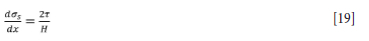
At x = 0, the edge of the pillar, a confining stress σh is applied as a result of the backfill placement. The seam-parallel stress component σs increases as x increases. The thin slice of rock between the dotted lines in Figure 11 is in equilibrium. This requires that

Equation [18] can be written in the form of a differential equation if the width of the slice tends to zero:
To solve Equation [19], a relationship between τ and σs needs to be assumed. If there is friction on the interfaces between the pillar and the hangingwall and footwall, τ is related to the normal stress, σn, by

where μ1 is the coefficient of friction and φ is the friction angle. We also assume that σn is related to the seam-parallel stress component σs by a failure relationship of the form

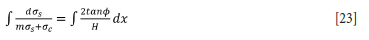
where σc and m are constants. Once failure occurs, σc can be considered as the strength of the failed pillar material and m is a slope parameter. Substituting Equations [20] and [21] into Equation [19] gives the a differential equation of the form

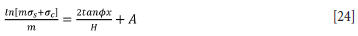
Equation [22] can be integrated if the variables are separated:
This equation has the following solution with the integration constant A:
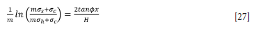
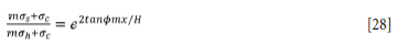
To include the effect of the backfill confinement, constant A is obtained from Equation [24] by applying the boundary condition σs = σh when x = 0. This gives the value of A as:

This can be inserted into Equation [24] to give

This can be simplified as
and
The solution of the seam-parallel stress is given by

From Equations [29] and [21], it follows that

Equation [21] defines the pillar material strength. In the TEXAN code, an extended model is implemented where the failure relationship for the intact pillar material is given by
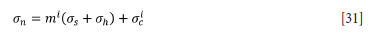
For the failed pillar material, the following parameters are adopted:

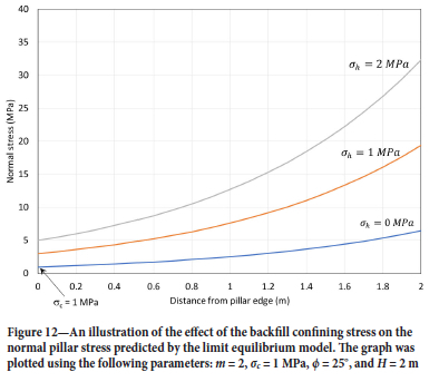
The requirements of mi > mf and σic > σfc must be met when selecting these parameters. To illustrate the behaviour of the model, Equation [30] is plotted in Figure 12 for different values of confining stress. Note how the normal stress in the failed zone of the pillar increases substantially for an increase in confining stress.
A numerical modelling study to simulate pillar slabbing at increasing depths
The TEXAN code used in this study is a displacement discontinuity boundary element code that was specifically developed to simulate a large number of small pillars in tabular layouts (Malan and Napier, 2006). It allows for the use of triangular boundary elements, thus circumventing the problem of 'partially mined' elements encountered using square element shapes. The 'two-dimensional' limit equilibrium model illustrated above had to be extended for use with actual irregular bord and pillar layouts (see Napier and Malan, 2021).
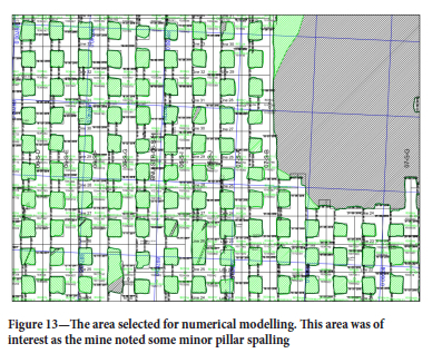
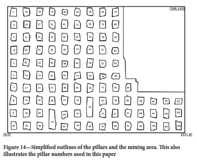
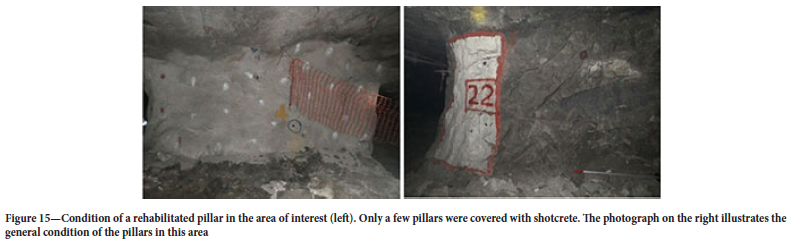
The geometry simulated in TEXAN is illustrated in Figure 13. This area was selected due to minor pillar spalling being observed. Backfilling is currently not used in the bord-and-pillar layouts of the Bushveld Complex and the modelling was therefore a theoretical study to investigate the potential benefits of backfill. To simplify the digitizing of the outlines and the meshing procedure, the pillar outlines were approximated with straight line segments as illustrated in Figure 14. The pillar numbers used in the study are given in this figure. The size of the area simulated was 225 m χ 150 m. Although the mine observed limited spalling in this area, the pillars were rehabilitated with shotcrete and they appeared to be in a good condition (see Figure 15).
For the modelling, the mined area was covered using a triangular mesh. The pillars also had to be meshed to enable the calculation of the average pillar stress (APS). The mesh used for the pillars had to be small enough to ensure an accurate simulation when using the limit equilibrium failure model. The average element size was 0.68 m2 in the mined area, and as an example of the pillars, it was 0.36 m2 for pillar 73.
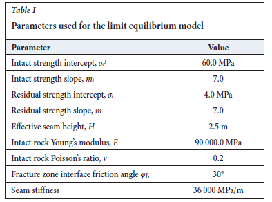
The density of the rock was assumed to be 3100 kg/m3 and the k-ratio was assumed to be unity in both horizontal directions. The depth below surface was approximately 290 m. Although there are slight variations in depth in the area of interest, the excavation was assumed to be horizontal to simplify the model. The limit equilibrium model as described above requires a large number of parameters to calibrate it and these are listed in Table I. The values selected were obtained from a back-analysis of a pillar mining experiment at this particular mine (see Napier and Malan, 2021). An extension of the model, not discussed in this paper, can allow for the time-dependent failure of the pillar material (Napier and Malan, 2014). This is typically not observed in shallow platinum mines and this effect was therefore ignored for this study.
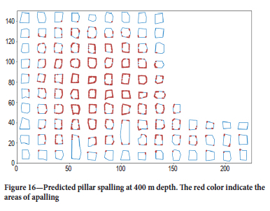
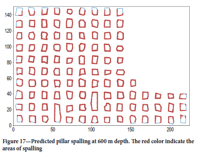
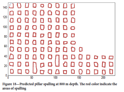
The selected parameters resulted in no spalling of the pillar edges for a simulation at a depth of 290 m, and this agrees with the observations made in this area. To investigate the stability of the revised pillar design at increasing depths, the layout shown in Figure 14 was also simulated at depths of 400, 600, and 800 m. Backfill was not included for these initial simulations. The limit equilibrium parameters that predicted no pillar failure at 290 m depth (Table I) were used for these simulations. The results are shown in Figures 16, 17, and 18. Note that the pillar spalling increases with depth until significant failure is observed at 800 m depth. The cores of the pillars are nevertheless still intact at this depth. This deterioration in pillar condition with depth agrees qualitatively with the decrease in extraction ratio with depth that can be sustained if a reasonable pillar factor of safety needs to be maintained (Figure 2).
A numerical modelling study to simulate the effect of backfill confinement
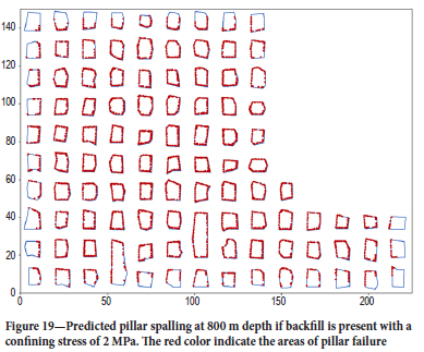
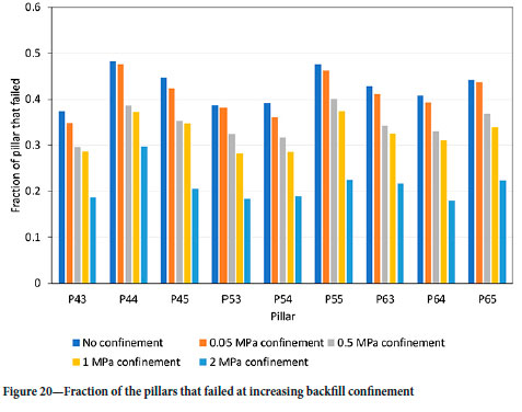
To simulate the effect of backfill, the extended limit equilibrium model, as described previously, was used. The same geometry as that simulated above was used and all simulations were conducted at a hypothetical depth of 800 m. As there is uncertainty regarding the amount of confinement that the backfill will exert, simulations with σh values of = 0.05, 0.5, 1, and 2 MPa were conducted. The fraction of the pillars that failed decreased with increasing confinement. The failure for 2 MPa confinement is illustrated in Figure 19. The same simulation without backfill confinement is shown in Figure 18. The benefit of confinement is also illustrated in Figure 20, where the fraction of the pillar that failed is shown for a few pillars. The fraction that failed is the number of elements that failed divided by the total elements for the particular pillar. Note that the failure decreases for increasing confinement, with a substantial reduction for a 2 MPa value. It is doubtful if such a magnitude of stress will be exerted by the backfill, unless there is substantial pillar dilation.
These results illustrate the value of the backfill confinement model in studies of the effect of backfill on pillar strength. The confinement exerted by backfill is not known, however, and therefore trial backfill sections in the mine, with sensitive instrumentation, will be required to obtain calibrated values for the model.
The scope of this initial study was to test a modelling approach that could be used to simulate the effect of backfill on pillar strength. This tool can now be used to simulate aspects such as the timing of backfill placement and partial backfill placement in selected areas. As part of future work, a thorough study of the sequence of backfill placement needs to be done. Preliminary work not reported in this paper (Ile, 2023) has indicated that simultaneous mining and backfilling is preferred to ensure that the pillars are confined before extensive failure occurs. This may not be practical in actual mines and a rigorous study needs to be conducted in terms of sequencing.
A further extension of the model in TEXAN is also required that will allow the coupling of the backfill lateral strain and resulting stress with pillar dilation. A novel scheme to compute the lateral dilation in the pillar has already been implemented in the TEXAN code by Professor John Napier. The next step will be to include the effect of the placed backfill and the interaction with pillar dilation.
Conclusions
The current pillar design methodology for bord-and-pillar layouts in the Bushveld Complex will result in a substantial decrease in extraction ratio at increasing depths. The extraction ratio is a simple decreasing linear function of the depth, H, and a gradient parameter. Backfill will increase the pillar strength, enabling increased extraction ratios. The use of backfill will also minimize the requirement for tailings storage on surface and the risk of environmental damage.
The literature survey indicated that backfill is extensively used in coal mines. This is done mostly for environmental considerations and to minimize the damage caused by subsidence, but also to increase the extraction ratio. In contrast, it seems as if backfill is rarely used in hard rock bord-and-pillar mines. Placement of backfill in sections of the mine may be challenging as containment barriers will have to be built between adjacent pillars. The sequence and timing of mining a section and placing the backfill will have to be carefully managed. This is a challenging aspect that requires additional research.
An extension of the limit equilibrium model in the TEXAN code proved to be useful for simulating the effect of backfill confinement on pillar strength. The amount of spalling at depth is substantially decreased if a moderate confinement is applied to the pillars. The confinement that will be induced by backfill in actual mining layouts is unknown and this needs to be quantified in future by installing sensitive instrumentation in backfill trial sections. Previous workers measured a lateral stress of 0.05 MPa in ash fill in a coal mine.
Areas where the pillar strength is reduced by weak layers may gain significant benefit from the placement of backfill. In some cases this may be the only method that will prevent large-scale collapses, and it requires further study.
Acknowledgements
This work forms part of the MEng study of Divine Ile at the University of Pretoria. The authors would like to thank Professor John Napier for his kind assistance with the backfill confinement model in TEXAN.
References
Baötang, S., Brett, P., Xün, L., Johnny Q., Ramesh, T., and Yi, D. 2017. Remediation and monitoring of abandoned mines. International Journal of Mining Science and Technology, vol. 27, no. 5. pp. 803-811. [ Links ]
Blight, G.E. and Clarke, L.E. 1983. Design and properties of stiff fill for lateral support. Proceedings of the International Symposium on Mining with Backfill, Lulea. Balkema, Rotterdam. 303-307. [ Links ]
Büddery, P.S. 1985. The hydraulic placement of PFA in underground coal mines for waste disposal and environmental control purposes. Proceedings of The Third Dimension - The Use of the Underground in South Africa. South African National Council on Tunnelling (SANCOT), Johannesburg. pp. 53-60. [ Links ]
Cai, S. 1983. A simple and convenient method for design of strength of cemented hydraulic fill. Proceedings of the International Symposium on Mining with Backfill, Lulea. Balkema, Rotterdam. pp. 405-412. [ Links ]
CouTO, P.M. and Malan, D.F. 2022. A limit equilibrium model to simulate the large-scale pillar collapse at the Everest Platinum Mine. Rock Mechanics and Rock Engineering. https://doi.org/10.1007/s00603-022-03088-z [ Links ]
Donovan, J.G. 1999. The effects of backfilling on ground control and recovery in thin-seam coal mining. MSc dissertation, Virginia Polytechnic Institute and State University. [ Links ]
Du Plessis, M., Malan, D.F., and Napier, J.A.L. 2011. Evaluation of a limit equilibrium model to simulate crush pillar behaviour. Journal of the Southern African Institute of Mining and Metallurgy, vol. 111. pp 875-885. [ Links ]
Esterhuyse, J.C. and Malan, D.F. 2018. Some rock engineering aspects of multi-reef pillar extraction on the Ventersdorp Contact Reef. Journal of the Southern African Institute of Mining and Metallurgy, vol. 118, no. 12. pp. 1285-1296. [ Links ]
Galvin, J.M and Wagner, H. 1982. Use of ash to improve strata control in bord and pillar workings. Proceedings of the International Symposium on Strata Mechanics, Newcastle-upon-Tyne, 5-7 April 1982. Farmer, I.W. (ed.). Elsevier. pp. 264-270. [ Links ]
Hedley, D.G.F. and Grant, F. 1972. Stope-and-pillar design for the Elliot Lake Uranium Mines. CIM Bulletin, vol. 65. pp. 37-44. [ Links ]
ICMM. 2022. Tailings reduction roadmap. London. [ Links ]
Ile, D. 2023. An investigation into the use of backfill to reinforce pillars in hard rock bord and pillar layouts. Draft MEng dissertation, University of Pretoria. [ Links ]
Jager, A.J. and Ryder, J.A. 1999. A Handbook on Rock Engineering Practice for Tabular Hard Rock Mines. Safety in Mines Research Advisory Committee, Johannesburg. [ Links ]
Kostecki, T. and Spearing, A.J.S., 2015. Influence of backfill on coal pillar strength and floor bearing capacity in weak floor conditions in the Illinois Basin. International Journal of Rock Mechanics and Mining Sciences, vol. 76, no. 3. pp. 55-67. [ Links ]
Laubscher, D.H. 1990. A geomechanics classification system for the rating of rock mass in mine design. Journal of the South African Institute of Mining and Metallurgy, vol. 90. pp 257-273. [ Links ]
Malan D.F. and Napier J.A.L. 2006. Practical application of the Texan code to solve pillar design problems in tabular excavations. Proceedings of the SANIRE Symposium "Facing the challenges", Rustenburg. South African National Institute of Rock Engineers. pp. 55-74. [ Links ]
Malan, D.F. and Napier, J.A.L. 2011. The design of stable pillars in the Bushveld mines: A problem solved? Journal of the Southern African Institute of Mining and Metallurgy, vol. 111. pp. 821-836. [ Links ]
Malan, D.F. and Esterhuyse, J.C. 2021. Work Package 4.3.1: Rock Engineering Criteria for Mechanised Mining. SAMERDI final report. Mandela Mining Precinct, Johannesburg. [ Links ]
Mo S., Canbulat I., Zhang C., Oh J., Shen B., and Hagan P. 2018. Numerical investigation into the effect of backfilling on coal pillar strength in highwall mining. International Journal of Mining Science and Technology, vol. 28. pp. 281-286. [ Links ]
Napier, J.A.L and Malan, D.F. 2007. The computational analysis of shallow depth tabular mining problems. Journal of the Southern African Institute of Mining and Metallurgy, vol. 107. pp. 725-742. [ Links ]
Napier, J.A.L. and Malan, D.F. 2014. A simplified model of local fracture processes to investigate the structural stability and design of large-scale tabular mine layouts. Proceedings of the 48th US Rock Mechanics / Geomechanics Symposium, Minneapolis. American Society for Rock Mechanics, Alexandria, VA. [ Links ]
Napier, J.A.L. and Malan D.F. 2018. Simulation of tabular mine face advance rates using a simplified fracture zone model. International Journal of Rock Mechanics and Mining Sciences, vol. 109. pp. 105-114. [ Links ]
Napier, J.A.L. and Malan D.F. 2021. A limit equilibrium model of tabular mine pillar failure. Rock Mechanics and Rock Engineering, vol. 54. pp. 71-89. [ Links ]
Palarski, J. 1993.The use of fly ash, tailings, rock and binding agents as consolidated backfill for coal mines. Proceedings of Minefill 93, Johannesburg. Southern African Institute of Mining and Metallurgy, Johannesburg. pp. 403-408. [ Links ]
Palarski, J. 1994. Design of backfill as support in Polish coal mines. Journal of the SouthAfrican Institute of Mining and Metallurgy, vol. 94, no. 8. pp. 218-226. [ Links ]
Pantelidis, L. 2019. The generalized coefficients of earth pressure: A unified approach. Applied Sciences, vol. 9. 5291. doi: 10.3390/app9245291 [ Links ]
Piper, P.S., Gürtunca, R.G., and Maritz, R.J. 1993. Instrumentation to quantify the in-situ stress-strain behaviour of mine backfill. Journal of the South African Institute of Mining and Metallurgy, vol. 93. pp. 109-120. [ Links ]
Rankine, W. 1856. On the stability of loose earth. Philosophical Transactions of the Royal Society of London, vol. 147. [ Links ]
Ryder, J.A. and Jager, A.J. 2002. A Textbook on Rock Mechanics for Tabular Hard Rock Mines. Safety in Mines Research Advisory Committee, Johannesburg. [ Links ]
Salamon, M.D.G. and Oravecz, K.I. 1976. Rock Mechanics in Coal Mining. Chamber of Mines of South Africa, Johannesburg. [ Links ]
Shamsabadi, A., Dasmeh, A., and Taciroglu, E. 2017. Guidelines for analysis and LRFD-based design of earth retaining structures. University of California, Los Angeles. [ Links ]
Shen, B., Poulsen, B., Luo, X., Qin, J., Thiruvenkatachari, R., and Duan, Y 2017. Remediation and monitoring of abandoned mines. International Journal of Mining Science and Technology, vol. 27, no. 5. pp. 803-811. [ Links ]
Squelch, A.P. 1993. A methodology for the selection of backfill as local support for tabular stopes in South African gold mines. Journal of the South African Institute of Mining and Metallurgy, vol. 93. pp. 9-15. [ Links ]
Stacey, T.R. and Page, C.H. 1986. Practical Handbook for Underground Rock Mechanics. Trans Tech Publications. [ Links ]
Tesarik, D.R., Seymour, J.B., and Yanske, T.R. 2009. Long-term stability of a backfilled room-and-pillar test section at the Buick Mine Missouri, USA. International Journal of Rock Mechanics and Mining Sciences, vol. 46. pp. 1182-1196. [ Links ]
Watson, B.P., Theron, W., Fernandes, N., Kekana, W.o., Mahlangu, M.P., Betz, G., and Carpede, A. 2021 UG2 pillar strength: Verification of the PlatMine formula. Journal of the Southern African Institute of Mining and Metallurgy, vol. 121, no. 8. pp. 449-456. [ Links ]
Zhang, J-X., Huang, P., Zhang, Q., Li, M., and Chen, Z-W. 2017. Stability and control of room mining coal pillars-taking room mining coal pillars of solid backfill recovery as an example. Journal of Central South University, vol. 24, no. 5. pp. 1121-1132. [ Links ]
Zhang, J., Li, M., Taheri, A., Zhang, W., Wu, Z., and Song, W. 2019. Properties and application of backfill materials in coal mines in China. Minerals, vol. 9. https://doi.org/10.3390/min9010053 [ Links ]
 Correspondence:
D.F. Malan
Email: francois.malan@up.ac.za
Received: 13 Nov. 2022
Revised: 4 Apr. 2023
Accepted: 30 May 2023
Published: May 2023

